Automatic Control Systems M Tech Electronics Control System


:")


- Slides: 28
Automatic Control Systems M. Tech. Electronics
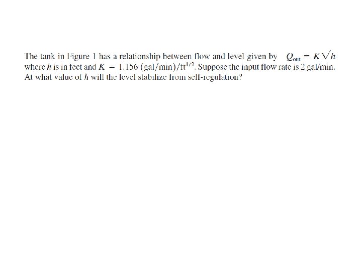
Control System • Process-Control Principles: – basic objective is to regulate the value of some quantity – reference value or set-point The Process: If the output flow rate is not exactly equal to the input flow rate, the level will drop, Qout >Qin if , or rise, if. Qout <Qin
• Human-Aided Control : – To regulate the level so that it maintains the value H, it will be necessary to employ a sensor to measure the level. This has been provided via a “sight tube, ” S, as shown in Figure 2. The actual liquid level or height is called the controlled variable. – The output flow rate is called themanipulated variableor controlling variable
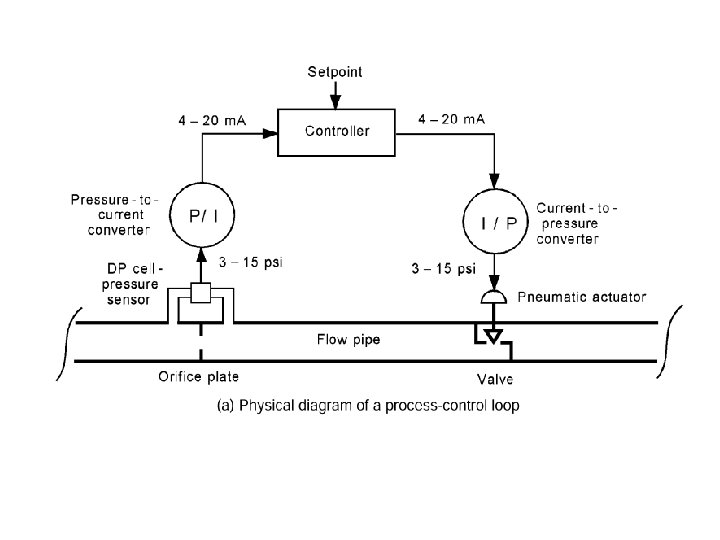
• Automatic Control: An instrument called a sensor is added that is able to measure the value of the level and convert it into a proportional signal, s. This signal is provided as input to a machine, electronic circuit, or computer called the controller. • The controller performs the function of the human in evaluating the measurement and providing an output signal, u, to change the valve setting via an actuator connected to the valve by a mechanical linkage
Elements of Process-Control system • Process: In general, a process can consist of a complex assembly of phenomena that relate to some manufacturing sequence. Many variables may be involved in such a process, and it may be desirable to control all these variables at the same time. There are single variable processes, in which only one variable is to be controlled, as well as multivariable processes. • Measurement: a measurement refers to the conversion of the variable into some corresponding analog of the variable, such as a pneumatic pressure, an electrical voltage or current, or a digitally encoded signal. The result of the measurement is a representation of the variable value in some form required by the other elements in the process-control operation
• Error Detector: In Figure 2, the human looked at the difference between the actual level, h, and the set point level, H, and deduced an error. This error has both a magnitude and polarity. • Controller: The next step in the process-control sequence is to examine the error and determine what action, if any, should be taken. This part of the control system has many names, such as compensator or filter, but controller is the most common. • Control Element: The final element in the process-control operation is the device that exerts a direct influence on the process; that is, it provides those required changes in the controlled variable to bring it to the set point. This element accepts an input from the controller, which is then transformed into some proportional operation performed on the process
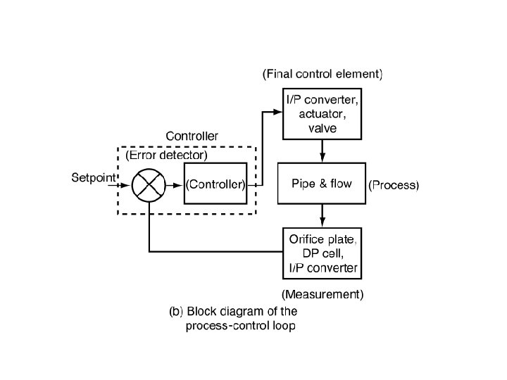
PROCESS-CONTROL BLOCK DIAGRAM
PROCESS-CONTROL BLOCK DIAGRAM • The controlled variable in the process is denoted by c in this diagram, and the measured representation of the controlled variable is labeled b. The controlled variable set-point is labeled r, for reference. • The controller uses the error input to determine an appropriate output signal p, which is provided as input to the control element. The control element operates on the process by changing the value of the controlling process variable, u. • The error detector is a subtracting-summing point that outputs an error signal, e = r - b, to the controller for comparison and action.
CONTROL SYSTEM EVALUATION • The variable used to measure the performance of the control system is the error, e(t), which is the difference between the constant set point or reference value, r, and the controlled variable, c(t). • A practical statement of control system objective is best represented by three requirements: 1. The system should be stable. 2. The system should provide the best possible steady-state regulation. 3. The system should provide the best possible transient regulation
• Stability: prior to turning on a control system, the controlled variable drifts in a random fashion and is not regulated. After the control system is turned on, the variable is forced to adopt the setpoint value, and all is well for awhile. Notice that some time later, however, the variable begins to exhibit growing oscillations of value—that is, an instability
• Steady-State Regulation: The objective of the best possible steady-state regulation simply means that the steady state error should be a minimum. Generally, when a control system is specified, there will be some allowable deviation, , about the setpoint. This means that variations of the variable within this band are expected and acceptable. External influences that tend to cause drifts of the value beyond the allowable deviation are corrected by the control system. • Transient Regulation: What happens to the value of the controlled variable when some sudden transient event occurs that would otherwise cause a large variation? For example, the setpoint could change. Suppose the setpoint in the aforementioned temperature case were suddenly changed to. Transient regulation specifies how the control system reacts to bring the temperature to this new setpoint. (Transient response)
• Evaluation Criteria: The question of how well the control system is working is thus answered by (1) ensuring stability, (2) evaluating steady-state esponse, and (3) evaluating the response to setpoint changes and transient effects • Damped Response: One type of criterion requires that the controlled variable exhibit a response such as that shown in Figure
• Cyclic Response: Another type of criterion applies to those cases in which the response to a setpoint change or transient is as shown in Figure – The nature of the response is modified by adjusting the control loop parameters, which is called tuning. There may be large maximum error but short duration or long duration with small maximum error, and everything in between
• A number of standard cyclic tuning criteria are used. Two common types are minimum area and quarter amplitude. In minimum area, the tuning is adjusted until the net area under the error-time curve is a minimum, for the same degree of excitation (setpoint change or transient). Figure shows the area as a shaded part of the curve. Analytically, this is given by • The quarter-amplitude criterion, shown in Figure , specifies that the ampli tude of each peak of the cyclic response be a quarter of the preceding peak. Thus, a 2 = a 1/4, a 3 = a 2/4, and so on.
ANALOG AND DIGITAL PROCESSING • Data Representation: – Analog Data: An analog representation of data means that there is a smooth and continuous variation between a representation of a variable value and the value itself – Digital Data: numbers are represented in terms of binary digits, also called bits, which take on values of one (1) or zero (0). • Data Conversions: – ADCs – DACs
• ON/OFF Control:
• Analog Control: True analog control exists when all variables in the system are analog representations of another variable
• Digital Control: – Supervisory Control:
• Direct Digital Control (DDC):
• Programmable Logic Controllers: – Earlier days relay control logic was used – recent years- PLCs have replaced relay control logics
ANALOG SIGNAL CONDITIONING Signal conditioning into several general types • Signal-Level and Bias Changes • Linearization • Conversions – Signal Transmission – Digital Interface • Filtering and Impedance Matching • Loading
Linearization Concept of Loading
• PASSIVE CIRCUITS – Divider Circuits – Bridge Circuits – RC Filters • OPERATIONAL AMPLIFIERS – Voltage Follower – Inverting Amplifier – Noninverting Amplifier – Differential Instrumentation Amplifier – Voltage-to-Current Converter – Current-to-Voltage Converter – Integrator – Differentiator – Linearization
DESIGN GUIDELINES 1. Define the measurement objective a. Parameter b. Range c. Accuracy d. Linearity e. Noise 2. Select a sensor a. Parameter b. Transfer function c. Time response d. Range e. Power 3. Design the analog signal conditioning (S/C) a. Parameter b. Range c. Input impedance d. Output impedance 4. Notes on analog signal-conditioning design
Design Problems • A sensor outputs a voltage ranging from to V. For interface to an analog-to digital converter, this needs to be 0 to 2. 5 V. Develop the required signal conditioning • Temperature is to be measured in the range of to with an accuracy of. The sensor is a resistance that varies linearly from to for this temperature range. Power dissipated in the sensor must be kept below 5 m. W. Develop analog signal conditioning that provides a voltage varying linearly from to V for this temperature range. The load is a high-impedance recorder. • A process signal varies from 4 to 20 m. A. The setpoint is 9. 5 m. A. Use a current-tovoltage converter and a summing amplifier to get a voltage error signal with a scale factor of 0. 5 V/m. A. • A pressure sensor outputs a voltage varying as 100 m. V/psi and has a 2. 5 - output impedance. Develop signal conditioning to provide 0 to 2. 5 Vas the pressure varies from 50 to 150 psi.