8255 Programming Mode By Dr RN Rajotiya 8255

8255 Programming Mode By Dr. RN Rajotiya

8255 • 8255 can operate in different modes i. e. • BSR mode is used for controlling individual bits of port C in read/write operation, Mode-0 is used when simple I/O activity is required on all three ports Mode-1 is used for handshake mode for Gp-A and G-B ports with handshake signals performed by Port-CLower and Port-Cupper Mode-2 is for bidirectional communication on Port-A with port-B in mode -0 or mode-1.
 Mode of Operation : BSR mode is used")
BSR Mode • Bit Set/Reset (BSR) Mode of Operation : BSR mode is used for Port-C to control read/write operation on individual pins of port C. The control word of the BSR mode is shown in figure Example of BSR Mode

IO Mode of Operation • The IO mode is used for reading and writing from or to IO device. The read write operations to/from IO devices can be performed in different modes. The control word setting for the IO mode is shown
 Two 8 -bit ports and two")
• Mode 0 Basic Functional Definitions: (i) Two 8 -bit ports and two 4 -bit ports, Any Port can be input or output (ii)Outputs are latched (iii) Input are not latched • Mode 1 Basic. Function. Definitions: (i) Group A and Group B i/o with and Port C 4 -bit control/data port for PA and PB (ii) Both inputs and outputs are latched. (iii) The 4 -bit ports of PC is used for control and status of the 8 -bit port. • Mode 2 Basic Functional Definitions : (i) Gp-A used as 8 -bit, bi-directional bus with port-C as 5 bit control hed (ii)The 5 -bit control port (Port C) is for the 8 -bit, bidirectional bus port (Por t A) (iii) Both inputs and outputs are latched

Interfacing Example • The control word setting for mode-0 is shown in following figure. Example: a) Identify port addresses in figure below. b) Write the control word to configure port A and port Cu as output port and port B and port CL as input port c) Write a program to read the DIP switches and display the reading from port B at port A and from port Cl at port Cu.

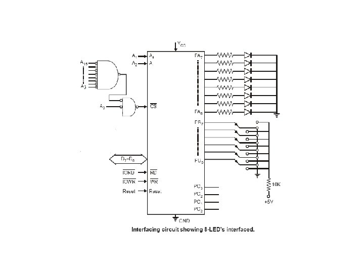
Example 1: -Interface an 8255 chip with 8086 to work as an I/O port. Initialize port A as output port, Port B as I/P port and Port C as O/P port. Port A address should be 0740 H. Writean ALP to sense switch positions SW 0–SW 7 connected at port B. The sensed pattern is to be displayed on port A, to which 8 LED's are connected, while port C lower displays number of on switches out of the total eight switches ? D 7 D 6 D 5 D 4 D 3 D 2 D 1 D 0 h. EX 1 0 0 0 1 0 =82 H i/o Mode PA Mode-0 PA – o/p PCU o/p PBPB-i/p Mode-0 Port Addresses PORT A 0740 PORT B 0742 PORT C 0744 CW 0746 PCLO/P

MOV OUT MOV IN MOV MOV X 1: ROL AL JNC INC X 2: DEC CH JNZ MOV ADD OUT HLT DX, AL, DX, DX, BL, CH, 0746 H 82 h AL 0742 H AL, DX 0740 H 00 H; Switch Count 08 H; Total Switchs X 2 BL X 1 AL, DX, BL 0 H AL

Example 2: -. Interface a 4 4 keyboard with 8086 using 8255, and write an ALP for detecting a key closure and return the key code in AL. The debouncing period for a key in 20 ms ? Answer: Here we use port-A as output port for selecting a row of keys, a low (‘ 0’) is outputted on PA 3 -0 one at a time while port-B is used as an input port for sensing a closed key ( A low on any of PB 3 -0. Hence the key board lines are selected one by one through Port-A and the Port-B lines are polled continuously till a key closure is sensed. Figure shows the interfacing of the 4 x 4 keyboard using a 8255 PPI To get the data from a keyboard requires three steps : (1) Detect a key press (2) Debounce the key press (3) Encode the key press The rows of the matrix are connected to four output port (PA 3 -0)lines. The column line of the matrix are connected to four input port (PB 3 -0) lines

Flowchart for keyboard interfacing using 8255

Example 3: -Interface an 8255 with 8086 at 80 H as an I/O address of Port. A. Interface five 7 segment displays with the 8255. Write an ALP to display 1, 2, 3, 4 and 5 over the 5 displays continuously as per their positions starting with 1 at the least significant position? Assuming a segment to light when a low signal is applied. The decimal to seven-segment code are No to be PA 7 PA 6 PA 5 PA 4 PA 3 PA 2 PA 1 PA 0 CODE displayed DP a b C d e f G 1 1 1 0 0 1 1 CF 2 1 0 0 1 1 92 3 1 0 0 1 1 1 86 4 1 1 0 0 CC 5 1 0 0 A 4 6 1 0 1 1 0 0 B 0 7 1 0 0 0 1 1 8 F 8 1 0 0 0 0 80 9 1 0 0 84 0 1 0 0 0 1 81

Interfacing Five 7 -segment Displays using 8255

Challenging Problem: Interface a 4 x 4 keypad and five 7 -segment displays using 8255 and WAP in assembly language to display a five digit number on the 7 -segments
- Slides: 14