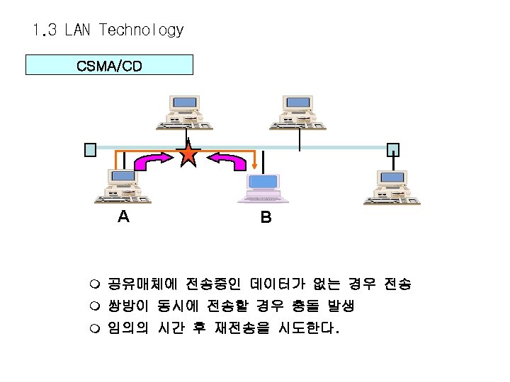
1 1 OSI 7 Layer Basic PeertoPeer Communication
![1. 1 OSI 7 Layer Basic Peer-to-Peer Communication Application Presentation Session Transport Router Transport 1. 1 OSI 7 Layer Basic Peer-to-Peer Communication Application Presentation Session Transport Router Transport](https://slidetodoc.com/presentation_image_h/1bef84865d3a387caf5c0441687d7f8e/image-1.jpg)
1. 1 OSI 7 Layer Basic Peer-to-Peer Communication Application Presentation Session Transport Router Transport Network Data Link Physical
![1. 1 OSI 7 Layer Basic Peer-to-Peer Communication Application Presentation Session Transport Router Transport 1. 1 OSI 7 Layer Basic Peer-to-Peer Communication Application Presentation Session Transport Router Transport](http://slidetodoc.com/presentation_image_h/1bef84865d3a387caf5c0441687d7f8e/image-2.jpg)
1. 1 OSI 7 Layer Basic Peer-to-Peer Communication Application Presentation Session Transport Router Transport Network Data Link Physical
![1. 1 OSI 7 Layer Basic Peer-to-Peer Communication Application Presentation Session Transport Router Transport 1. 1 OSI 7 Layer Basic Peer-to-Peer Communication Application Presentation Session Transport Router Transport](http://slidetodoc.com/presentation_image_h/1bef84865d3a387caf5c0441687d7f8e/image-3.jpg)
1. 1 OSI 7 Layer Basic Peer-to-Peer Communication Application Presentation Session Transport Router Transport Network Data Link Physical
![1. 2 LAN Overview LAN 이란? 서버 LAN 터미널 : Local Area Network 1. 2 LAN Overview LAN 이란? 서버 LAN 터미널 : Local Area Network](http://slidetodoc.com/presentation_image_h/1bef84865d3a387caf5c0441687d7f8e/image-4.jpg)
1. 2 LAN Overview LAN 이란? 서버 LAN 터미널 : Local Area Network
![1. 2 LAN Overview LAN 이란? 서버 LAN 터미널 : Local Area Network 1. 2 LAN Overview LAN 이란? 서버 LAN 터미널 : Local Area Network](http://slidetodoc.com/presentation_image_h/1bef84865d3a387caf5c0441687d7f8e/image-5.jpg)
1. 2 LAN Overview LAN 이란? 서버 LAN 터미널 : Local Area Network
![1. 3 LAN Technology IEEE 802 LAN 표준 Application Presentation Session Transport Network Data 1. 3 LAN Technology IEEE 802 LAN 표준 Application Presentation Session Transport Network Data](http://slidetodoc.com/presentation_image_h/1bef84865d3a387caf5c0441687d7f8e/image-6.jpg)
1. 3 LAN Technology IEEE 802 LAN 표준 Application Presentation Session Transport Network Data Link LLC MAC Physical < OSI > < IEEE >
![1. 3 LAN Technology IEEE 802 LAN 표준 Data Link L L C 10 1. 3 LAN Technology IEEE 802 LAN 표준 Data Link L L C 10](http://slidetodoc.com/presentation_image_h/1bef84865d3a387caf5c0441687d7f8e/image-7.jpg)
1. 3 LAN Technology IEEE 802 LAN 표준 Data Link L L C 10 Base 5 10 Base 2 10 Base. T 토큰 버스 1, 5, 10 Mbps IEEE 802. 5 CSMA /CD IEEE 802. 4 Physical IEEE 802. 3 M A C IEEE 802. 2 토큰링 4, 16 Mbps
![](http://slidetodoc.com/presentation_image_h/1bef84865d3a387caf5c0441687d7f8e/image-8.jpg)
![1. 3 LAN Technology 10 Base 5 최대500 M MAU(Tranceiver) COAX(thick) AUI Cable (Tranceiver 1. 3 LAN Technology 10 Base 5 최대500 M MAU(Tranceiver) COAX(thick) AUI Cable (Tranceiver](http://slidetodoc.com/presentation_image_h/1bef84865d3a387caf5c0441687d7f8e/image-9.jpg)
1. 3 LAN Technology 10 Base 5 최대500 M MAU(Tranceiver) COAX(thick) AUI Cable (Tranceiver cable) 최소2. 5 M
![1. 3 LAN Technology 10 Base. T HUB(REPEATER) 100 M UTP 1. 3 LAN Technology 10 Base. T HUB(REPEATER) 100 M UTP](http://slidetodoc.com/presentation_image_h/1bef84865d3a387caf5c0441687d7f8e/image-10.jpg)
1. 3 LAN Technology 10 Base. T HUB(REPEATER) 100 M UTP
![1. 3 LAN Technology 10 Base. T UTP Cabling(EIA 568 B규격) PIN NO. 케이블 1. 3 LAN Technology 10 Base. T UTP Cabling(EIA 568 B규격) PIN NO. 케이블](http://slidetodoc.com/presentation_image_h/1bef84865d3a387caf5c0441687d7f8e/image-11.jpg)
1. 3 LAN Technology 10 Base. T UTP Cabling(EIA 568 B규격) PIN NO. 케이블 제작 실습 1 2 3 4 5 6 7 8 COLOR white/orange white/green blue white/blue green white/brown 기 능 TD+ TDRD+ RD-
![](http://slidetodoc.com/presentation_image_h/1bef84865d3a387caf5c0441687d7f8e/image-12.jpg)
![1. 3 LAN Technology 고속 이더넷 Gigabit Etherner Media Options and Standards IEEE 802. 1. 3 LAN Technology 고속 이더넷 Gigabit Etherner Media Options and Standards IEEE 802.](http://slidetodoc.com/presentation_image_h/1bef84865d3a387caf5c0441687d7f8e/image-13.jpg)
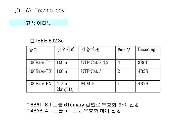
1. 3 LAN Technology 고속 이더넷 Gigabit Etherner Media Options and Standards IEEE 802. 3 Z IEEE 802. 3 ab
![1. 3 LAN Technology Ethernet Frame Ethernet frame(Ethernet _II) Preamble 8 bytes Destination 6 1. 3 LAN Technology Ethernet Frame Ethernet frame(Ethernet _II) Preamble 8 bytes Destination 6](http://slidetodoc.com/presentation_image_h/1bef84865d3a387caf5c0441687d7f8e/image-14.jpg)
1. 3 LAN Technology Ethernet Frame Ethernet frame(Ethernet _II) Preamble 8 bytes Destination 6 bytes Source 6 bytes Ethertype 2 bytes - FCS의 범위 : DA, SA, Ethertype, Data - DATA 길이 : 46 - 1500 옥텟 Data 46 - 1500 FCS 4 bytes
![1. 3 LAN Technology 802. 3 Frame Preamble 7 bytes SFD Destination 6 bytes 1. 3 LAN Technology 802. 3 Frame Preamble 7 bytes SFD Destination 6 bytes](http://slidetodoc.com/presentation_image_h/1bef84865d3a387caf5c0441687d7f8e/image-15.jpg)
1. 3 LAN Technology 802. 3 Frame Preamble 7 bytes SFD Destination 6 bytes 1 byte Source 6 bytes Length 2 bytes Data FCS 46 -1500 4 bytes
![1. 3 LAN Technology 802. 2 LLC Frame DSAP 1 byte SSAP 1 byte 1. 3 LAN Technology 802. 2 LLC Frame DSAP 1 byte SSAP 1 byte](http://slidetodoc.com/presentation_image_h/1bef84865d3a387caf5c0441687d7f8e/image-16.jpg)
1. 3 LAN Technology 802. 2 LLC Frame DSAP 1 byte SSAP 1 byte Control 1 -2 bytes Network layer data
![1. 3 LAN Technology SNAP Frame DSAP SSAP Control 1 byte OUI Ethertype Network 1. 3 LAN Technology SNAP Frame DSAP SSAP Control 1 byte OUI Ethertype Network](http://slidetodoc.com/presentation_image_h/1bef84865d3a387caf5c0441687d7f8e/image-17.jpg)
1. 3 LAN Technology SNAP Frame DSAP SSAP Control 1 byte OUI Ethertype Network layer data 3 byte 2 byte SNAP header (5 byte) -DSAP, SSAP : 0 x. AA - Control : 0 x 03 - OUI (Organizational Unit Identifier) : TCP/IP 일 경우 0
![1. 3 LAN Technology 각 Frame에 대한 비교 Preamble Destination Source Ethertype Data 8 1. 3 LAN Technology 각 Frame에 대한 비교 Preamble Destination Source Ethertype Data 8](http://slidetodoc.com/presentation_image_h/1bef84865d3a387caf5c0441687d7f8e/image-18.jpg)
1. 3 LAN Technology 각 Frame에 대한 비교 Preamble Destination Source Ethertype Data 8 bytes 6 bytes 2 bytes 46 - 1500 Ethernet Frame FCS 4 Destination Source Length 802. 2헤더와 FCS 6 bytes 2 bytes 46 -1500 4 IEEE 802. 3 + LLC 802. 2 Frame Preamble SFD 7 bytes 1 DSAP SSAP Control 1 byte 1 -2 bytes Network layer data LLC 802. 2 Frame
![](http://slidetodoc.com/presentation_image_h/1bef84865d3a387caf5c0441687d7f8e/image-19.jpg)
![1. 4 Internetworking Technology Bridging LAN 1 A 3 3 LAN 2 LAN 3 1. 4 Internetworking Technology Bridging LAN 1 A 3 3 LAN 2 LAN 3](http://slidetodoc.com/presentation_image_h/1bef84865d3a387caf5c0441687d7f8e/image-20.jpg)
1. 4 Internetworking Technology Bridging LAN 1 A 3 3 LAN 2 LAN 3 1 브리지1 2 1 브리지2 2 B
![1. 4 Internetworking Technology Switching Shared High Speed Line Bridge Dedicated Line Internal Architecture 1. 4 Internetworking Technology Switching Shared High Speed Line Bridge Dedicated Line Internal Architecture](http://slidetodoc.com/presentation_image_h/1bef84865d3a387caf5c0441687d7f8e/image-21.jpg)
1. 4 Internetworking Technology Switching Shared High Speed Line Bridge Dedicated Line Internal Architecture • Multi-port Bridge Switch
![1. 4 Internetworking Technology Redundant Topology Server/host X Router Y Segment 1 Segment 2 1. 4 Internetworking Technology Redundant Topology Server/host X Router Y Segment 1 Segment 2](http://slidetodoc.com/presentation_image_h/1bef84865d3a387caf5c0441687d7f8e/image-22.jpg)
1. 4 Internetworking Technology Redundant Topology Server/host X Router Y Segment 1 Segment 2 q Redundant topology eliminates single points of failure q Redundant topology causes broadcast storms, multiple frame copies, and MAC address table instability problems
![1. 4 Internetworking Technology Broadcast Storm Server/host X Router Y Segment 1 Switch A 1. 4 Internetworking Technology Broadcast Storm Server/host X Router Y Segment 1 Switch A](http://slidetodoc.com/presentation_image_h/1bef84865d3a387caf5c0441687d7f8e/image-23.jpg)
1. 4 Internetworking Technology Broadcast Storm Server/host X Router Y Segment 1 Switch A Broadcast Switch B Segment 2 q Switches continue to propagate broadcast traffic over and over
![1. 4 Internetworking Technology Spanning Tree Protocol 100 base. T Designated port (F) Root 1. 4 Internetworking Technology Spanning Tree Protocol 100 base. T Designated port (F) Root](http://slidetodoc.com/presentation_image_h/1bef84865d3a387caf5c0441687d7f8e/image-24.jpg)
1. 4 Internetworking Technology Spanning Tree Protocol 100 base. T Designated port (F) Root bridge Nonroot bridge SW X SW Y Designated port (F) Nondesignated port (B) x 10 base. T q One root bridge per network q One root port per nonroot bridge q One designated port per segment
![1. 4 Internetworking Technology Spanning Tree Protocol 100 base. T Designated port (F) Root 1. 4 Internetworking Technology Spanning Tree Protocol 100 base. T Designated port (F) Root](http://slidetodoc.com/presentation_image_h/1bef84865d3a387caf5c0441687d7f8e/image-25.jpg)
1. 4 Internetworking Technology Spanning Tree Protocol 100 base. T Designated port (F) Root bridge Nonroot bridge SW X SW Y Designated port (F) Nondesignated port (B) x 10 base. T q One root bridge per network q One root port per nonroot bridge q One designated port per segment
![1. 4 Internetworking Technology Root Bridge 결정 Switch X Default priority 32768 (8000 hex) 1. 4 Internetworking Technology Root Bridge 결정 Switch X Default priority 32768 (8000 hex)](http://slidetodoc.com/presentation_image_h/1bef84865d3a387caf5c0441687d7f8e/image-26.jpg)
1. 4 Internetworking Technology Root Bridge 결정 Switch X Default priority 32768 (8000 hex) MAC 0 c 001111 BPDU Switch Y Default priority 32768 (8000 hex) MAC 0 c 002222 BPDU = Bridge protocol data unit Root bridge = Bridge with the lowest bridge ID Bridge ID = Bridge priority + bridge MAC address
![1. 4 Internetworking Technology Spanning Tree Port States Spanning-tree transitions each port through several 1. 4 Internetworking Technology Spanning Tree Port States Spanning-tree transitions each port through several](http://slidetodoc.com/presentation_image_h/1bef84865d3a387caf5c0441687d7f8e/image-27.jpg)
1. 4 Internetworking Technology Spanning Tree Port States Spanning-tree transitions each port through several different state: Blocking Listening Learning Forwarding
![1. 4 Internetworking Technology VLAN • Segmentation 3 rd floor • Flexibility 2 nd 1. 4 Internetworking Technology VLAN • Segmentation 3 rd floor • Flexibility 2 nd](http://slidetodoc.com/presentation_image_h/1bef84865d3a387caf5c0441687d7f8e/image-28.jpg)
1. 4 Internetworking Technology VLAN • Segmentation 3 rd floor • Flexibility 2 nd floor 1 st floor • Security SALES HR ENG 1 VLAN = 1 broadcast domain = Logical network (subnet)
![1. 4 Internetworking Technology VLAN 동작 Switch B Switch A Trunk Fast Ethernet Red 1. 4 Internetworking Technology VLAN 동작 Switch B Switch A Trunk Fast Ethernet Red](http://slidetodoc.com/presentation_image_h/1bef84865d3a387caf5c0441687d7f8e/image-29.jpg)
1. 4 Internetworking Technology VLAN 동작 Switch B Switch A Trunk Fast Ethernet Red VLAN Black VLAN Green VLAN q Each logical VLAN is like a separate physical bridge q VLANs can span across multiple switches q Trunks carries traffic for multiple VLANs
![1. 4 Internetworking Technology VLAN Tagging ISL trunks enable VLANs across a backbone VLAN 1. 4 Internetworking Technology VLAN Tagging ISL trunks enable VLANs across a backbone VLAN](http://slidetodoc.com/presentation_image_h/1bef84865d3a387caf5c0441687d7f8e/image-30.jpg)
1. 4 Internetworking Technology VLAN Tagging ISL trunks enable VLANs across a backbone VLAN Tag added by incoming port VLAN Tag stripped by forwarding port § Performed with ASIC Inter-Switch Link carries VLAN identifier § Not intrusive to client stations, client does not see the ISL header § Effective between switches, routers and switches, switches and servers with ISL network interface cards
![1. 5 WAN Overview WAN이란? q WANs connect remote sites. q Connection requirements vary 1. 5 WAN Overview WAN이란? q WANs connect remote sites. q Connection requirements vary](http://slidetodoc.com/presentation_image_h/1bef84865d3a387caf5c0441687d7f8e/image-31.jpg)
1. 5 WAN Overview WAN이란? q WANs connect remote sites. q Connection requirements vary depending on user requirements, cost, and availability.
![1. 6 WAN Technology WAN connections 1. 6 WAN Technology WAN connections](http://slidetodoc.com/presentation_image_h/1bef84865d3a387caf5c0441687d7f8e/image-32.jpg)
1. 6 WAN Technology WAN connections
![1. 6 WAN Technology WAN Protocols HDLC PPP X. 25 Frame Relay. . . 1. 6 WAN Technology WAN Protocols HDLC PPP X. 25 Frame Relay. . .](http://slidetodoc.com/presentation_image_h/1bef84865d3a387caf5c0441687d7f8e/image-33.jpg)
1. 6 WAN Technology WAN Protocols HDLC PPP X. 25 Frame Relay. . .
![1. 6 WAN Technology HDLC frame format • Uses a proprietary data field to 1. 6 WAN Technology HDLC frame format • Uses a proprietary data field to](http://slidetodoc.com/presentation_image_h/1bef84865d3a387caf5c0441687d7f8e/image-34.jpg)
1. 6 WAN Technology HDLC frame format • Uses a proprietary data field to support multiprotocol environments • Supports only single-protocol environments
![1. 6 WAN Technology PPP Overview • PPP can carry packets from several protocol 1. 6 WAN Technology PPP Overview • PPP can carry packets from several protocol](http://slidetodoc.com/presentation_image_h/1bef84865d3a387caf5c0441687d7f8e/image-35.jpg)
1. 6 WAN Technology PPP Overview • PPP can carry packets from several protocol suites using NCP. • PPP controls the setup of several link options using LCP.
![1. 6 WAN Technology Layering PPP elements • PPP: A data link with network 1. 6 WAN Technology Layering PPP elements • PPP: A data link with network](http://slidetodoc.com/presentation_image_h/1bef84865d3a387caf5c0441687d7f8e/image-36.jpg)
1. 6 WAN Technology Layering PPP elements • PPP: A data link with network layer services
![1. 6 WAN Technology PPP session establishment • Two PPP authentication protocols: PAP and 1. 6 WAN Technology PPP session establishment • Two PPP authentication protocols: PAP and](http://slidetodoc.com/presentation_image_h/1bef84865d3a387caf5c0441687d7f8e/image-37.jpg)
1. 6 WAN Technology PPP session establishment • Two PPP authentication protocols: PAP and CHAP
![1. 6 WAN Technology Frame Relay Topology • Frame Relay default: nonbroadcast, multiaccess (NBMA) 1. 6 WAN Technology Frame Relay Topology • Frame Relay default: nonbroadcast, multiaccess (NBMA)](http://slidetodoc.com/presentation_image_h/1bef84865d3a387caf5c0441687d7f8e/image-38.jpg)
1. 6 WAN Technology Frame Relay Topology • Frame Relay default: nonbroadcast, multiaccess (NBMA)
![1. 6 WAN Technology Frame Relay 일반 1. 6 WAN Technology Frame Relay 일반](http://slidetodoc.com/presentation_image_h/1bef84865d3a387caf5c0441687d7f8e/image-39.jpg)
1. 6 WAN Technology Frame Relay 일반
![1. 6 WAN Technology Frame Relay Address mapping – Use LMI to get locally 1. 6 WAN Technology Frame Relay Address mapping – Use LMI to get locally](http://slidetodoc.com/presentation_image_h/1bef84865d3a387caf5c0441687d7f8e/image-40.jpg)
1. 6 WAN Technology Frame Relay Address mapping – Use LMI to get locally significant DLCI from the Frame Relay switch. – Use Inverse ARP to map the local DLCI to the remote router’s network layer address.
- Slides: 40