Wireless Theory and Regulations For unlicensed wireless networks


- Slides: 33
Wireless Theory and Regulations For unlicensed wireless networks Presentation by Wyatt Zacharias Except where otherwise noted this work is licensed under the Creative Commons Attribution-Share. Alike 4. 0 International License. To view a copy of this license, visit http: //creativecommons. org/licenses/bysa/4. 0/.
The Decibel, notation: d. B is a logarithmic unit used to represent a ratio between two values, most commonly power or intensity. In common usage the decibel is used to indicate intensity in reference to a set base unit. In wireless context, the base unit used is the milliwatt (m. W). In order to communicate what the reference unit is, a letter will be appended to d. B. For milliwatts, the letter m is appended: d. Bm.
Decibel Calculation •
Antenna Gain An antenna’s ability to convert input power to radiated power is described as gain. Antenna gain is also measured in d. B, with two common reference units used. d. Bi – The antennas gain in reference to a theoretical radiator that emits equally in all directions d. Bd – The antennas gain in reference to a dipole radiator. 1 d. Bd = 2. 15 d. Bi
Polarization The polarization of an antenna refers to the orientation of the electric field (E-Plane) in respect to the earth’s surface. Because electromagnetic radiation is a transverse wave, the magnetic field (H-Plane) will be at 90° to the electric field. For a dipole and other linear radiators, the E-Plane will be along the length of the radiator, thus an antenna running perpendicular to the earth’s surface has vertical polarization, while an antenna running parallel to the surface has horizontal polarization. Image by P. wormer / CC-BY-SA 3. 0 Unported
Other Polarization Patterns In addition to linear polarization an antenna can be circularly or elliptically polarized. This means that the electric and magnetic fields are in a constant state of rotation, 90° apart. Because of the losses of a linear polarization mismatch, circular polarization is most common with satellites where polarization of a linear antenna on the satellite could not be controlled. Image Public Domain
Image Public Domain
Polarization Losses •
Radiation Patterns The radiation pattern of an antenna defines the strength of the radiation at different positions around the antenna. Radiation patterns are typically expressed in two graphs, one depicting the E-Plane radiation, and the other depicting the H-Plane radiation. Each graph depicts the radiation in a 360° radius with the antenna in the center.
Image Public Domain
Transmission Line Transmission line can be separated into two different types, balanced and unbalanced. Unbalanced line, also known as coaxial cable, consists of a center conductor and an outer foil braid shield separated by an insulator. Balanced line consists of two equally sized conductors connected in parallel with each other at a fixed distance apart. In unbalanced lines the electromagnetic field is almost entirely contained within the shield, this allows coaxial cable to be run near power lines and other metal objects without interference. In balanced lines the electromagnetic field is located between the two conductors. This makes the signal susceptible to interference from external objects, such as metal and other materials.
Photo by Apolkhanov / CC-BY-SA 3. 0 Unported Photo by Miikka Raninen / CC-BY-SA 3. 0 Unported Photo by Gerry Ashton / CC-BY-SA 3. 0 Unported
Transmission Line Loss Different cables offer different amounts of power handling and signal loss depending on application. Balanced line typically has good power handling and signal loss figures, however the susceptibility to physical interference and its high impedance make it harder to work with. Coaxial line has the advantage that its impedance is almost always compatible, and it is does not suffer from physical interference. Coaxial line tends to have a higher signal loss however, this can be compensated for with higher quality cable.
Typical Line Losses As frequency increases so does transmission loss in the cable. Losses become very significant as frequency passes 1 Ghz. Table Copyright 2002 -2015 universal-radio. com
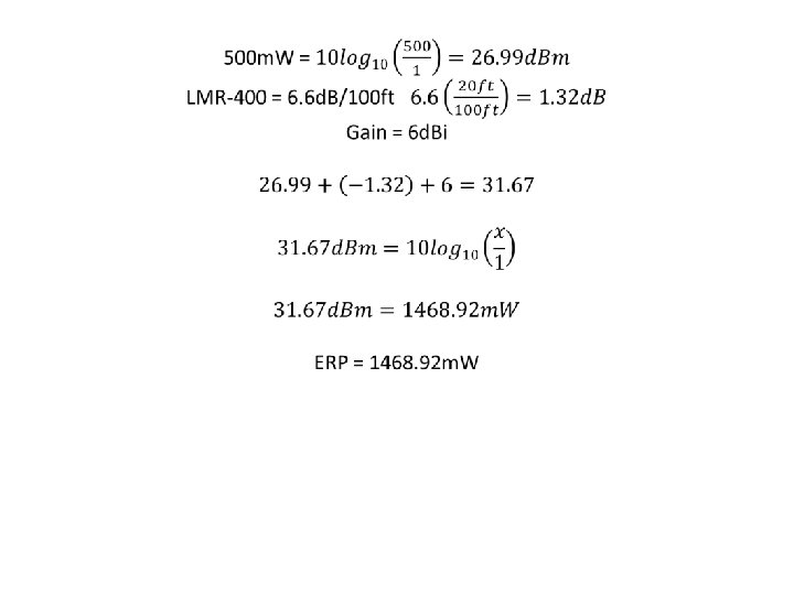
Calculating ERP Once all gains and losses are known the effective radiated power of the transmitter can be calculated. To do this, a sum of all gains and losses is taken, and then it can be converted to watts. Lets calculate the ERP for a 500 m. W 2. 4 GHz transmitter with a 6 d. Bi antenna connected with 20 ft of LMR-400.
Free Space Path Loss •
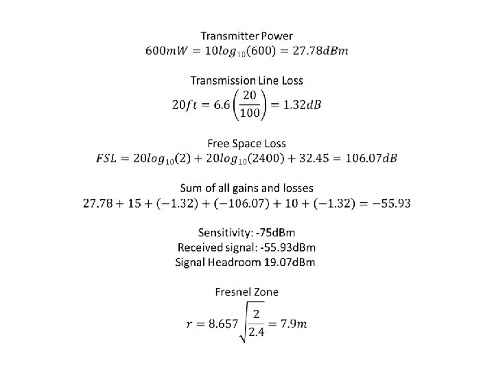
Fresnel Zones A Fresnel zone is an elliptically shaped area stretching between a transmitter and a receiver. In theory there are multiple Fresnel zones increasing in size around the longitudinal axis between transmitter and receiver. In practice the first Fresnel zone is the most important, and has the largest effect on signal degradation. Objects in this area are capable of disrupting the transmission path of a signal, causing constructive or destructive interference.
Fresnel Zone Calculations •
Point to Point Links Calculating the overall feasibility of a point to point link is similar calculating ERP, all gains and losses from the transmitter are summed. Additionally the gains and losses of the receiving station, along with the receiver sensitivity and the Fresnel zone between the sites will be taken into account. Lets calculate a 2 Km 2. 4 GHz link hoping to achieve 150 Mbit/s 802. 11 n with a 600 m. W transmitter with a 15 d. Bi antenna, and a receiver with 10 d. Bi antenna and a -75 d. Bm sensitivity to achieve 150 Mbit/s each with 20 ft of LMR-400 on each antenna.
5 GHz Specific Technologies DFS – Dynamic Frequency Selection is the ability for a transmitter to dynamically change the output frequency in order to avoid interference with other stations TPC – Transmitter Power Control is the ability for the transmitter to reduce power by up to 6 d. B in order to reduce interference to other nearby stations.
5 GHz Operation The radio spectrum between 5. 150 GHz – 5. 850 GHz is widely used for commercial and government purposes such as radionavigation, Earth satellite imaging, weather radar, militar radar, and satellite communication. Surprisingly even with all this commercial use, unlicensed use is being permitted, and regulations are evolving to continue to allow unlicensed use on the 5 GHz band. Use of the 5 GHz band comes with more responsibility though as interference on this band can disrupt critical commercial and military operation.
Regulations
Radio Regulations in Canada Radio communication and licensing is handled by Industry Canada. Relevant I. C. Documents: • RSS-Gen - General radio regulations • RSS-210 - License exempt radio regulations • RSS-247 - DTS, FHS, and LE-LAN regulations FCC regulations are not applicable. Most online resources will cite FCC regulations which are not relevant to transmitters in Canada.
Regulations for 2. 4 GHz Transmitters Under RSS-247 no distinction is made between DTSs (Digital Transmission Systems) and LE-LANs (License Exempt LANs). The regulations for DTSs are the relevant rules for 2. 4 GHz LE-LAN devices. The only significant regulation for 2. 4 GHz transmitters is that transmitter power may not exceed 1 W and EIRP may not exceed 4 W. An exception to this rule is point to point systems which may exceed 4 W EIRP by means of a higher gain antenna, but are still limited to 1 W transmitter output. There is no specified maximum EIRP for point to point systems.
Regulations for 5 GHz Transmitters The 5 GHz spectrum is split into 5 separate sections with different rules applying to the different sections. • 5150 -5250 MHz – Indoor use only • 5250 -5350 MHz – Power restricted • 5470 -5600 MHz – Frequency restrictions • 5650 -5725 MHz – Frequency restrictions • 5725 -5850 MHz – Standard restrictions
5150 -5250 MHz •
5250 -5350 MHz •
5470 -5600 MHz & 5650 -5725 MHz •
5725 -5850 MHz No restrictions on location Channels: 142 -165 Output power is limited to 1 W. If an antenna with more than 6 d. Bi of gain is used output power and spectral density must be decreased by the amount in d. B that the antenna exceeds 6 d. Bi. Fixed point to point systems may employ an antenna gain of more than 6 d. Bi without a reduction in power. Emissions within 10 MHz of the band edges may not exceed -17 d. Bm/MHz Emissions beyond 10 MHz of the band edges may not exceed -27 d. Bm/MHz
Dynamic Frequency Selection Devices operating in the 5250 -5350 MHz, 5470 -5600 MHz, and 56505725 MHz must be capable of DFS for the purpose of radar avoidance with the following requirements: For EIRP < 200 m. W the detection threshold is -62 d. Bm For output < 200 m. W and EIRP < 1 W the threshold is -64 d. Bm Devices must continually monitor for radar signals between normal transmissions. The device must see that a channel is clear for at least 60 seconds before beginning transmission. If a radar signal is detected all transmissions on that channel must stop within 10 seconds. A channel will not be operated on for at least 30 minutes after a radar signal was detected.
Questions