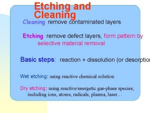
Wet Etching I Introduction Definition of etching The


- Slides: 23

Wet Etching (I)

Introduction Definition of etching: The process of selectively removing material by chemical, electrolytic, or physical means. Chemical = a. k. a. “chemistry, ” chemical reactions to convert solid material into soluble products. Physical = bombardment, as in dry etching

Introduction Etching is used to remove material from selected regions: • The regions may be dictated by patterning, such as a photoresist pattern that was previously made with photolithography. PR Film Substrate Idealized Case • Or the region could be an entire wafer or substrate, as in the wet stripping of an entire blanket layer. Film Substrate

Types of Etching There are two types of etching: – Wet etching • Uses liquid chemicals to etch. • Usually creates a unique isotropic profile. • Uses only chemistry to etch. – Dry etching • Uses plasma to etch. • Creates a more ideal etch (can create isotropic or anisotropic). • Uses both chemistry and bombardment to etch.

Introduction Etch vs. Dissolve (with respect to wet chemistry) Etch: a chemical reaction takes place to convert the film into a soluble product. Dissolve: no chemical reaction is necessary. A good solvent is used to bring the material into solution without undergoing a chemical reaction. Note: these terms are sometimes used interchangeably in nanofab processes.

Introduction Over Time Substrate 1 Polymer Film Substrate Solvent Chemical Reaction + 2 Soluble Product 3

Introduction • Cleaning may also be considered as wet a type of wet etching. • In this case, the materials being etched away include unwanted residues (organics, metals, etc. ) and particulate matter. • Creates a controlled surface on which to build things (e. g. , devices). Before Cleaning: Unknown Surface State After Cleaning: Controlled Surface

Example Cleaning Steps Name Components Removes… Piranha Mixture Sulfuric Acid, Hydrogen Peroxide Organics and Metals SC 1 Ammonium Hydroxide, Hydrogen Peroxide, Water Particles and Organics SC 2 Hydrochloric Acid, Hydrogen Peroxide, Water Metallic Residues HF or BOE Hydrofluoric acid, Buffer, Water Native Oxide (Si. O 2) Proper cleaning generally involves many sequential steps and therefore can generate a significant volume of waste: Piranha Water SC 1 Water SC 2 Water HF Water Drying

Figure of Merit: Etch Rate • Etch Rate = thickness etched per time • Usually desired rates are in the 10’s to 100’s of nm/min • If rates are too high, may be difficult to control the process • Too low of rates = long etch times

Figure of Merit: Selectivity • The ability of an etchant to attack one material and not another. • Wet chemical etching can be very selective, or not very selective depending upon the application. • Represented as a ratio: Etch Rate of Material 1 Selectivity = Etch Rate of Material 2 Layer 2 Protects Layer 1 2 1 Layer 2 is Adjacent to Layer 1 versus 2 1 2

Aspect Ratio D Aspect Ratio = W Public Domain: Image Generated by CNEU Staff for free use, 2009 Generally, high aspect ratios are harder to achieve than low ones. High aspect ratio features are very desirable for many applications. Due to its isotropic nature, it is difficult to obtain high aspect ratios with wet etching. Dry etching is usually required to fabricate high aspect ratio features.

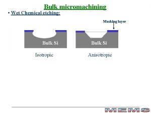
Isotropic vs. Anisotropic Isotropic: The same in all directions. Material is removed (etched) at the same rate in all directions (lateral and vertical). Anisotropic: Directions are not equal. Etch rate in vertical direction is different from (greater than) etch rate in lateral direction. Isotropic Anisotropic

Anisotropy RL A=1 RV RL = Lateral Etch Rate RV = Vertical Etch Rate RL RV

Isotropic • Isotropic = the same in all directions • • • RL = R V Characteristic wet etch profile. Tends to undercut during etching. Strictly chemical etching. No physical energy component.

Pure Isotropic Etching RL = RV RL =1 -1=0 A=1 RV Undercutting Penn Sate Center for Nanotechnology Education and Utilization

Undercut Before Etching No Undercut Film to be Etched Substrate or Etch Stop Layer (not susceptible to etchant) Masking Layer (not susceptible to etchant)

Undercut Example Undercut: Lateral etching that occurs under the masking (protecting) layer. Expressed as a distance (length). 10 um 3 4 3 Original Pattern Size = 10 um Resulting Feature Size = 4 um Undercut = 3 um each side

Anisotropic • Anisotropic: directions are not equal • RV RL, usually RV > RL – Commonly attained using dry etching. – Characteristic dry (plasma) etch profile, a function of chemistry and bombardment. • Chemistry – the chemical reactions that take place on the substrate. • Bombardment – kinetic ion energy directed at the substrate.

Anisotropic • Anisotropic: directions are not equal – This type of profile can be achieved by some wet etches, in special cases. – Wet etchants etch some single crystal materials faster in certain crystallographic directions, resulting in anisotropic etch profiles. – Example: TMAH and KOH wet etching of silicon with certain crystal orientation.

Pure Anisotropic Etching RL = 0 RL =1 -0=1 A=1 RV

Anisotropic Silicon Wet Etches Actual etch profiles of deep grooves etched into a (110) or (100) silicon substrate using TMAH and KOH: (a) 26% TMAH 86 o. C; (b) 40% KOH 70 o. C K. Sato et al. r. Sensors and Actuators 73(1999)131– 137

Anisotropic Etching of Single Crystals Crystal: a solid material consisting of very well-ordered atoms or molecules with a repeating pattern that extends in all three dimensions. Directions and faces are not necessarily the same. Crystals may be anisotropic due to the packing arrangement of their constituent atoms or molecules. Weaker Bonds Stronger Bonds RV RL In this idealized case: RV > R L

Wet vs. Dry Etching Generally… • Wet Etching: higher selectivity but lower anisotropy • Dry Etching: lower selectivity but higher anisotropy But…special conditions can exist which may give increased control over selectivity and/or anisotropy.
 Isotropic
 Wet etching vs dry etching
 Wet wet wet
 Wet etching
 Engraving serial numbers
 High aspect ratio contact
 Etch undercut
 Etching cleaning process
 Result
 Scratchboard etching
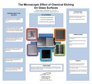
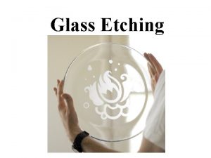
 Chemical etching glass
 Difference between reactive sourcing and strategic sourcing
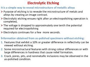
 Electrolytic etching
 Harc etch
 Ion etching
 Reactive ion etching
 Micromechanical retention
 Exlisis
 Atomic layer etching
 Electrolytic etching metallography
 Hình ảnh bộ gõ cơ thể búng tay
 Slidetodoc
 Bổ thể
 Tỉ lệ cơ thể trẻ em
