VIITTIFR Collaboration C S Garde Vishwakarma Institute of

VIIT-TIFR Collaboration C S Garde Vishwakarma Institute of Information Technology, Pune
 Year No. of projects No. of students No.")
VIIT-TIFR Collaboration (Final Year Engineering Projects) Year No. of projects No. of students No. of faculty (VIIT) 2 7 9 12 12 No. of scientists/ engineers (TIFR) 1 8 15 10 10 2009 -2010 -2011 -2012 -2013 -2014 1 8 11 13 17 2014 -2015 Total 15 65 2 19 33 38 47 (46+1 ME) 47 186 Departments (VIIT) E&TC E& TC, Comp, IT 10 8 E& TC, Comp, IT

VIIT students in TIFR Sr. No. 1 2 3 4 5 6 7 Name of student (Batch) Sanket Kamathe (2010) Ameya Deshpande (2010) Raj Patil (2011) Project at TIFR Post Silicon Photo Multiplier Jr. Research (Si. PM) Fellow Tera Hertz Spectroscopy Jr. Research Fellow Plasmonics NRIM National Photonics Aniket Patil (2011) Plasmonic Interconnects Fellowship Harshad Surdi (2012) Tera Hertz Spectroscopy Jr. Research Fellow Raghunandan Shukla Si. PM, VLSI, Embedded Scientific Officer (2011) “C” Sarrah. Lokahandwala FPGA based systems, Si. PM Jr. Research (2013) Fellow Lab at TIFR High Energy Physics, Mumbai Solid State Electronics, Mumbai High Energy Physics, Mumbai
 Suraj Kolhe (2012) VLSI,")
Sr. No. 8 Name of student Project at TIFR (Batch) Suraj Kolhe (2012) VLSI, Embedded 9 10 Serin V. John (2013) High voltage Embedded Sameer Saraf (2013) Embedded 11 Akhil Kurup (2014) 12 Akshay Manjare Embedded, Instrumentation (2014) Prathamesh THz, Plasmonics Deshmukh (2014) 13 14 Post Lab at TIFR Jr. Research Cosmic Rays Fellow Laboratory, Ooty DAS, Jr. Research Fellow Project Scientific Atomic Physics, Officer Mumbai FPGA based systems, Si. PM Jr. Research High Energy Fellow Physics, Mumbai Jr. Research Cosmic Rays Fellow Laboratory, Ooty Jr. Research Solid State Fellow Electronics, Mumbai Pankaj Rakshe (BE- Embedded, Instrumentation Scientific Officer Cosmic Rays 2011; ME-2014) “D” Laboratory, Ooty

Software Technology Utilization in TIFR �Data Convertors: Text to ROOT �Web based Static ROOT Plots �Dynamic Plots through remote ROOT access �Web based Inventory management – Scintillator and Muon Detectors

Hardware Technology Utilization in TIFR � 32 -channel High Speed FPGA based Counters �High Voltage Monitoring �Bulk Data Transfer using USB protocol

Director, TIFR interacting with Bharat Agarwal, Managing Trustee

TIFR Delegation �Prof Mustansir Barma, Director, TIFR �Prof Sunil Gupta, PI - CRL, Ooty �Prof A Venu Gopal �Dr Pravata Mohanty �Mr Jagdeesan �Mr Raghunandan Shukla �Mr Pankaj Rakshe �Ms Sarrah Lokandwala �Mr Prathamesh Deshmukh �Mr Akhil Kurup

VIIT Faculty �Prof Prasad Khandekar, HOD, E&TC �Prof Vivek Aranake �Prof Shailesh Thaware �Prof Mandar Karyakarte �Prof Ketan Raut �……

Interaction with students
 • Data Conversion (2011 -2012) l Converted data collected from")
Software Projects (Computer Department) • Data Conversion (2011 -2012) l Converted data collected from detectors in text format to ROOT format • Web access to static Plots (2011 -2012) l l Kept the graph files in specific location Persons having access to the system can see those plots through web interface
 • Dynamic ROOT Plots (2012 -13) Data at CRL, Ooty Persons")
ROOT Plots (Contd) • Dynamic ROOT Plots (2012 -13) Data at CRL, Ooty Persons across the globe can access Ooty ROOT data and issue command to plot graphs for fixed parameters • Dynamic ROOT Plots (2013 -14) True dynamic plot with user specified parameters for SC ROOT files l l l
 • ROOT dynamic Plot (2014 -15) Plot dynamic graphs with different")
ROOT Plots (Contd) • ROOT dynamic Plot (2014 -15) Plot dynamic graphs with different parameters and multiple plots on single canvas like Temperature, SC ROOT data, weather data versus time l
 Scintillator detectors have several subsystems and are")
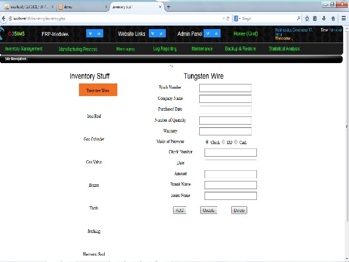
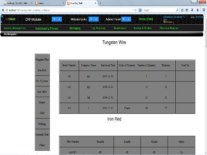
Inventory Management • Inventory Management (2011 -12) Scintillator detectors have several subsystems and are connected to different devices “Inventory” system for maintaining detailed information accessible over web Data Base and User Interface developed l l l
 User Interfaces and authentication • Inventory management")
Inventory Management • Inventory management (2012 -13) User Interfaces and authentication • Inventory management (2013 -14) Completed linking between tabs e. g. if ADC port from detector changed, will be reflected in ADC page l l
 To complete inventory management with reports with")
Inventory Management • Inventory management (2014 -15) To complete inventory management with reports with flexibility to print or export to excel. l
 On GPU using CUDA • CORSIKA parallization")
CORSIKA parallelization • CORSIKA parallization (2012 -13) On GPU using CUDA • CORSIKA parallization (2013 -14) On CPU using OPENMP Random number generation parallelization Not effective • CORSIKA parallization (2014 -15) On CPU using OPENMP l l l

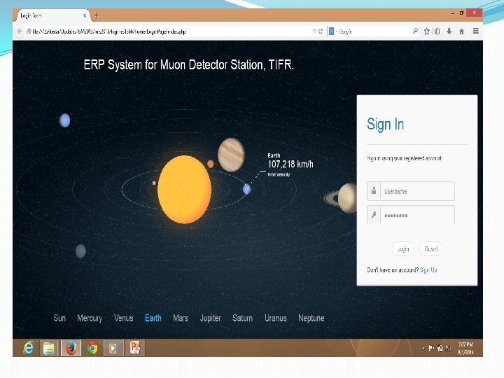
ERP System for muon Detector Existing System q Maintenance of inventory of PRC manufacturing processes -Excel sheet, Paper work q Log records -Log book q Manual tasks -Job costing and purchase order inventory -Analysis and Report generation -Backup and restore -User management

System Objectives �Automating all the business processes like -Regular Data analysis. -Report generation. -Monitoring. -User Management -Back-up and Restore. -Log recording �Alert Systems (SMS alerts and emails). �Two way authentication.

ER- Diagram Deployment Diagram

Schema Diagram

Proposed System and Work done �Completed Work: �Inventory Management module �Manufacturing process module �Currently Working on: �Report Generation �Session Management �Remaining Modules: �Job Costing �Statistical Analysis �Back-up and Restore �Two way authentication
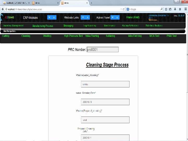
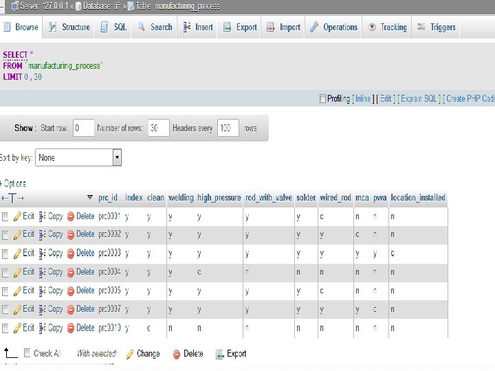

Summary �All the data which is viewed and searched is implemented using ajax which avoids refreshing of page and improves performance. �Implemented auto suggest like ‘google’ which suggests the proportional counter (prc) id’s while typing in the input box and it also prevents assigning worker a wrong prc. �Both inventory and manufacturing module have been linked together. �Deep linking of ajax done. �Allowing user to add, edit, search and delete on demand by developing dynamic web pages.

Project plan

MULTI-SESSION MULTI-THREADED DATA BANKING

DAILY FILES GENERATED ~27 GB ü Data Files • Scintilator files (16 GB/650 files per day) • Scintilator Rate files (1. 2 GB/24 files per day) • Muon files (1 GB/130 files per day) • Muon Angle files (4 GB/20 files per day) • Weather files (<1 MB/1 file per day) • EF files (30 MB/1 file per day) ü Root Files (5 GB compressed data) üText files (<50 MB)

4 Muon 4 Stations 400 Scintillator Mumbai office Weather Station CRL, TIFR data Backup System

CURRENT SYSTEM �No backup of the data at remote location �Dependency on Blue ray Disc for data storage �No policy of transferring the data from the server �Need Compression

v. OBJECTIVES : �Multi-threaded backup operations using client-server pull and/ or push architecture. �Data compression and decompression �Failure handling and recovery during the backup process. �Tracking of all the backup process states and user activities. �Scheduled as well as unscheduled data backup. �Report generation.

STRATEGY üCheckpoints üCompression üLogs üSecurity üIncremental üRestore üMultithreading üMultisession

PRESENT STATUS �Studied Backup tools �Implemented the Concept of multithreading �Implemented a Client Server Program for File Transfer in different ways �Implemented File Splitter and Joiner program

File Splitter and Joiner Programs �File Splitter Program: This program is to split files into multiple threads(parts) at one side (client or server) then send split files to the other side. �File Joiner Program: When the other side(server or client) receives split files Joiner combine all split parts and restores original file.

SPLITTER-JOINER MAIN FORM Note : - This is for manual working

SPLITTER PAGE

BROWSE THE FILE TO SPLIT

AFTER SPLITTING AND JOINING IT WILL SHOW

JOINER PAGE

BROWSE ONLY FIRST SPLIT PART TO JOIN Note: - Joining will be done automatically, this form is designed only to test working of joiner.

FORM FOR MULTIPLE DATA FILES SELECTION

FORM FOR MULTIPLE ROOT FILES SELECTION

FORM FOR MULTIPLE TEXT FILES SELECTION

WORK PLAN • Send files to multiple clients, also receive files from multiple clients. • Automation of file splitting and joining. • Sending multiple files at a time. • Maintaining logs.

TECHNOLOGY USED �Platform : Cent Operating System �Languages : � Java �Java. Script �CSS �Database: My. SQL. �Server: Apache Tomcat.

64 channel Muon Counter – Hardware Board Design �Schematics Completed. �Few bugs are identified from current custom boards. �Proper corrective steps are taken in new design

On-going work � 2 bugs in existing board found/ corrected on new board schematic �All FPGA board module Schematics completed/ ARM board schematic �Started H/W debugging �All libraries required for board designing (FPGA / ARM) developed �Start level shifter design/datasheet study/ ARM board Design

On-going work �Start of schematic design/Completed Power schematic �Study of datasheets of various components used on ARM controller board �Interacted with Mr. Karkhanis (SBL Pvt. Ltd. (Pune)). Guidelines regarding precautions in high speed PCB design

On-going work �Redesign the board. �Power FPGA Board, check for functionality. �Keep only those function blocks, which are required.

Schematics: 1 Fig-8. 1 POWER

Schematics: 2 Fig-8. 2 LEVEL SHIFTER
")
Schematics: 3 Fig 8. 3 FPGA (with channels connected)

Schematics: 4 Fig 8. 4 PHYSICAL LAYER MAC IC

Routing Students will visit CRL and learn and design PCB

TRIGGER LOGIC DESIGN FOR EAS SCINTILLATION DETECTORS

Work progress so far Ø Level 0 Trigger for inner three rings has been implemented. Ø Design is successfully tested with BASYSY-2 development board which contains XILINX Spartan 3 E FPGA.
 Ø Nomenclature : •")
FPGA: Xilinx Spartan 6 ( xc 6 lx 9 ) Ø Nomenclature : • XC : Commercial device with speed grade: -2 (time taken for a signal to pass through the entire chip [input-output]). • 6 : Spartan 6 device. • LX 9 : Actual FPGA chip name. Ø Ø Ø Package : TQG 144 (other : BGA, CSG, etc. ) Slices : 1430 (each slice has 4 LUT’s and 8 FF) Logic Cells : 9152 (6 -input LUT) Flip Flops: 11440 Distributed RAM : 90 kb

Future scope Ø Level 1 trigger Ø Implementing multiple counters at every stage which increments every time an event occurs Ø e. g. no. of times one particular detector is hit Ø No. of times line or pulse is generated Ø No. of times level 0 trigger has occurred.

Charge Integrator

SPECIFICATION � Design a amplifier for specifications: Rise time: 1 ns Fall time: 10 ns Very high frequency(approx 1. 5 Ghz) with bandwidth of 350 Mhz Input: 200 -500µV. Output: 5 m. V, retaining the pulse close to original 10 ns time period as well. � Design of a Pulse shaper The pulse is required to be stretched by at least 100 times so proper ADC can be used. � A circuit that could convert the analog pulse to digital , considering the bandwidth requirement. 63

Present Status �Designed amplifier using transistor and Op-Amp �Designed PCB and given for manufacturing �Will solder and test circuits next month

Solar PV System

PROJECT SCHEMATIC Clean Energy ! Green Energy !! Safe Energy !!!

noitcenno. C lena. P Buck. Boost Converter V 081 retrevn. I CA dao. L !!! ygren. E efa. S !! ygren. E neer. G ! ygren. E nael. C

12 SOLAR PANELS OF 280 Watts each Clean Energy ! Green Energy !! Safe Energy !!!

Solar Panel Description �Each solar panel is of 280 Wpp, total 3. 36 k. W power �Maximum power point is 35 V for each panel �Max current rating of each panel is 7 A Clean Energy ! Green Energy !! Safe Energy !!!

Battery Description � 2 battery banks with 14 batteries each of voltage 12 V connected in series i. e. total of 168 -180 V. �Battery rating is 66 Ah. �Maximum charging current is 10 A. Clean Energy ! Green Energy !! Safe Energy !!!

Charging of battery from single panel ON PANEL 1 is connected to BATT SET 2 directly through bus OFF OFF ON Negative sign indicates charging of batteries Clean Energy ! Green Energy !! Safe Energy !!!

Charging of battery using both panel Rectified DC from mains PANEL 1 ON PANEL 2 ON OFF BATT SET 1 BATT SET 2 ON Voltage Current LOAD Clean Energy ! Green Energy !! Safe Energy !!!

UPS Electrical Connection Scheme MAINS AC Rectifier INV LOAD BAT MAINS AC + Rectifier - SOLAR PV 1 SOLAR PV 2 BAT 1 BAT 2 Clean Energy ! Green Energy !! Safe Energy !!!

Power from both panels are utilized to drive the load as well as charge batteries ` PANEL 1 PANEL 2 BATT 1 BATT 2 ON ON OFF ON ON Current supplied to load as well as batt set 2 through common bus from solar panels LOAD Voltage Current The total current from solar is divided depending upon the output load consumption Clean Energy ! Green Energy !! Safe Energy !!!

If load current is less than solar current, the remaining current is utilized for charging batteries PANEL 1 PANEL 2 BATT 1 BATT 2 ON LOAD OFF ON Charging battery Clean Energy ! Green Energy !! Safe Energy !!! ON Connected to AC load through inverter Load current is less than panel current

If load current is greater than solar current, the remaining current is supplied from batteries PANEL 1 ON LOAD PANEL 2 OFF BATT 1 BATT 2 OFF ON ON Load is connected to AC load through inverter` Load current is greater than panel current Battery is providing current load Clean Energy ! Green Energy !! Safeto Energy !!!
: 1. 04 k. W Inverter Output Voltage: 230")
Observations Loading condition (20 PC’s ON): 1. 04 k. W Inverter Output Voltage: 230 V AC Current: 6 Amp AC Load power factor: 0. 75 Battery voltage: 171 V DC Current: 7. 5 Amp DC Losses in inverter: (1. 28 -1. 04)k. W = 240 W Clean Energy ! Green Energy !! Safe Energy !!!

Buck Boost Converter Input voltage variation: 100 - 240 V Output voltage constant: 180 V Current max rating: 7 A Tested up to 100 V Buck Boost Converter SOLAR PANELS 180 V DC bus Load Sharing INVERTER Sensing Board AC Load µC MOSFET DRIVER Clean Energy ! Green Energy !! Safe Energy !!! Battery Bank

Buck boost basic scheme Constant 180 V output Panel Input Voltage Variation (100 -240 V) Buck mode: Vo=D*Vin Boost mode: Vo=Vin/(1 -D) Clean Energy ! Green Energy !! Safe Energy !!!
 �Generated PWM pulses for driving MOSFET using microcontroller. �Integrated the")
Present status (Buck Boost) �Generated PWM pulses for driving MOSFET using microcontroller. �Integrated the buck boost and successfully achieved constant voltage 180 V using the buck boost in no load condition with an input voltage from 100 -250 V. �Testing with load being done

margai. D kcol. B SAD Panel 1 Panel 7 Panel 2 Panel 8 Panel 3 Panel 9 Panel 4 Panel 10 Panel 5 Panel 11 Panel 6 Panel 12
 �Completed mounting and testing of sensor board. �Tested voltage linearity,")
Present status (Data Acquisition) �Completed mounting and testing of sensor board. �Tested voltage linearity, current sensing and temperature sensing. �Verified the output of MUX. Data acquisition board was designed, fabricated and initial testing was done. Clean Energy ! Green Energy !! Safe Energy !!!

Voltage sense testing Panel terminals Voltage divider network to obtain voltage in a range of 0 -5 V for the module range of 0 -42 V Clean Energy ! Green Energy !! Safe Energy !!!

Current sense testing Hall sensor of ± 25 A rating and 100 m. V/A output sensitivity. 2. 5 V for 0 A current Clean Energy ! Green Energy !! Safe Energy !!!

Temperature measurement testing results For temp measurement sensor LM 35 was used with sensitivity of 10 m. V/˚C. OPAMP is used to amplify the signal and get an output in the range of 0 -5 V. Amplifier linearity graph Clean Energy ! Green Energy !! Safe Energy !!!

Solar Power Generation at Ooty �Terrace area available: 413 sq. m �No. of panels (2 x 1 m 2) that can be installed(280 W capacity each): 72 �Assured power generation for 1 yr: 33400 units(k. Wh) �Daily average generation: 91. 5 units(k. Wh) �Power capacity: 20 k. W 12 rows of 6 panel each in series with max power voltage 35 V/panel and MPPT current 8 A/row Clean Energy ! Green Energy !! Safe Energy !!!

Future – DC bus Rs. 21 lakhs funded by ISRO Clean Energy ! Green Energy !! Safe Energy !!!
 �SMPS replaced by")
Savings with respect to Conventional Solar System �UPS redundant (20% saving) �SMPS replaced by DC-DC converter(20% saving) �Conventional tube light by LED tubelight(10% saving) �Induction motor fan replaced by BLDC motor(35% saving) Clean Energy ! Green Energy !! Safe Energy !!!

Acknowledgements �Scientists/ Engineers of TIFR �Faculty of VIIT �Students

Thank You
- Slides: 90