UTRA TDD Overview Agostinho Castro alcastroinesporto pt Rui


- Slides: 29

UTRA TDD Overview Agostinho Castro alcastro@inesporto. pt Rui Sarmento Castro rui. castro@inescporto. pt Telecommunications and Multimedia Unit

Outline • Introduction – Definition, Principles and Characteristics • UTRA TDD Physical Channels Structure – Frame, Slot and Burst • Mapping of Transport Channels to Physical Channels • Power Control • Resource Allocation – Code Allocation Strategies (FDD) – Dynamic Channel Allocation (TDD) • UTRA TDD Interference Scenario Telecommunications and Multimedia Unit

Introduction • Two implementations are proposed for the UTRA (UMTS Terrestrial Radio Access) physical layer: – Frequency Division Duplex (FDD) Time 190 MHz Uplink 5 MHz Downlink Frequency 5 MHz – Time Division Duplex (TDD) Time Downlink Guard Period Uplink 5 MHz Telecommunications and Multimedia Unit Frequency

UTRA FDD – Requires the allocation of two frequency bands: one for the uplink and another for the downlink. – FDD radio units need duplexers in order to separate the incoming and outgoing signals at the antenna. – FDD does not allocate efficiently the available bandwidth for all types of services. Telecommunications and Multimedia Unit

UTRA TDD – TDD mode can use the same frequency band for both the uplink and the downlink by allocating distinct time slots to the two links. – Each time slot can be allocated either to the uplink or to the downlink. – TDD terminals do not need duplexer hence have less hardware complexity than FDD terminals. – TDD requires better time synchronization between the users than FDD • the base station cannot be allowed to transmit at the same time as the mobiles stations. • a guard period must be included in the protocol to make sure only one link is active at the same time. Telecommunications and Multimedia Unit

UTRA TDD Characterics • Utilization of unpair band; • Asymmetric uplink/downlink capacity allocation; • Discontinuos transmission; Time Downlink Guard Period Uplink • Interference between uplink and downlink; • Reciprocal channel. Telecommunications and Multimedia Unit Frequency

UTRA TDD • Combination of TDMA and CDMA – TD/CDMA • Direct Sequence CDMA (SS Technique) Uplink (MS -> BS) Downlink (BS -> MS) Time Frequency 10 ms 5 MHz Telecommunications and Multimedia Unit

UTRA TDD Code Time Frequency 10 ms 5 MHz Telecommunications and Multimedia Unit

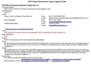
UTRA TDD Physical Channel Structure TDD Frame 10 ms (15 timeslots) Spreading Codes BS TX Part MS TX Part GUARD PERIOD DATA 0, 666 ms Slot 0, 666*15=10 ms MIDAMBLE Burst Telecommunications and Multimedia Unit DATA

UTRA TDD Frame Structure • Switching point configurations – Multiple-switching-point (symetric DL/UL allocation) 10 ms – Multiple-switching-point (asymetric DL/UL allocation) 10 ms – Single-switching-point (asymetric DL/UL allocation) 10 ms Telecommunications and Multimedia Unit

Asymmetrical Capacity Allocation • Part of the slots must be fixed for – Downlink: BCH and SCH – Uplink: RACH • Other slots could be allocated according to need (DCA) Telecommunications and Multimedia Unit

Physical Channels • A Physical Channel in TDD is a BURST • A BURST is a combination of DATA part, a MIDAMBLE and a GUARD PERIOD • Several BURST can be transmitted at the same time from one transmitter. The DATA part must use different OVSF channelisation codes (the same scrambling code) • The duration of a BURST is one time slot Telecommunications and Multimedia Unit

Bursts Types • Burst Type 1 – Burst Type 1 can be used for up- and downlink; • Burst Type 2 – Burst Type 2 can be used for up- and downlink; • Burst Type 3 – Burst Type 3 is used for uplink only; Training Sequence Traffic Burst, PRACH Burst, SCH Burst Telecommunications and Multimedia Unit

Mapping of the Transport Channels to Physical Channels Telecommunications and Multimedia Unit

Power Control • Power Control – Low SF – low processing gain; – Uplink – Open Loop; – Downlink – SIR based closed inner loop. Telecommunications and Multimedia Unit

Dynamic Resource Allocation • FDD – Code Allocation Strategies • TDD – Channel Allocation – Resource Unit (RU) Allocation - timeslot and code (frequency) • Resource Allocation to cells (Slow DCA) • Resource Allocation to bearer Service (Fast DCA) Telecommunications and Multimedia Unit

Dynamic Channel Allocation • Resource Allocation to cells (Slow DCA) – RNC • Resource Allocation to bearer Service (Fast DCA) – Base Station Telecommunications and Multimedia Unit

Dynamic Channel Allocation (DCA) BS Nk RNC Slow DCA A Slow DCA N BS N(k+1) BS A 1 Fast DCA Nk BS A 2 Fast DCA A 1 Fast DCA N(k+1) Fast DCA A 2 Telecommunications and Multimedia Unit

TDD Interference Scenario High power BS 1 blocks MS 2 in BS 2 BS 1 R R T T T T T MS 1 T T R R R R R MS 2 T T T T R R R BS 2 R R R R T T T T BS 1 BS 2 MS 1 Telecommunications and Multimedia Unit MS 2

Packet Access • A packet service session contains one or several PACKET CALLS depending on application; • PACKET CALLS constitues a BURSTY SEQUENCE OF PACKETS; Telecommunications and Multimedia Unit

Packet Data Traffic • Characteristics – Session arrival process; – Number of packet calls per session; – Reading time between packets calls; • Reading time starts when the last packet of the packet call is completely received by the user and ends when user makes a request for the next packet call. – Time interval between two packets inside a packet call; – Packet size. Telecommunications and Multimedia Unit

Packet Data Traffic Telecommunications and Multimedia Unit

Non-real Time Packet Service • Characteristics from air interface point of view – Packet data is BURSTY; – Packet data tolerates longer delay then real-time services; – Packets can be retransmited by Radio Link Control (RLC). Telecommunications and Multimedia Unit

WCDMA Packet Access • Packet allocations in WCDMA are controlled by the PACKET SCHEDULER (PS) • Packet Scheduler Functions – Divide the avaiable air interface Telecommunications and Multimedia Unit

Packet Data Service • Model of Operation in WCDMA (uplink) – Packet data can be transmited in three ways • Packet transmission on the RACH; • Packet transmission on a dedicated channel (when there is already a dedicated channel available). Telecommunications and Multimedia Unit

Packet Transmission on the RACH • Packet is included in the message part of the access burst; • If there is a small amount of data to transmit; – Short message service; – Short text-only e-mails. • No explicit reservation is carried out; • No explicit channel assignment is needed; • Risk of collisions on the common RACH; • Not power-controlled. Telecommunications and Multimedia Unit

Packet Transmission on Dedicated Channels • MS first sends a resource request message, indicating what type of traffic is to be transmitted; • Network evaluates whether the MS can be assigned the necessary resource; – YES • A resource allocation message (RAM) is transmitted on the FACH. • RAM consists of a set of transport formats and the specification of a dedicated channel to use for the packet transmission, • (out of this set) MS will use one transport format to transmit the data on a DCH; Telecommunications and Multimedia Unit

Packet Transmission on Dedicated Channels (cont. ) • EXACTLY which transport format the MS may use and at what time the MS may initiate its transmission is EITHER transmitted TOGETHER with RAM (traffic load is low) OR is indicated in a separate capacityallocation message AT LATER TIME; • The second alternative is used in cases where the load is high AND the MS is not allowed to immediately transmit the packet; Telecommunications and Multimedia Unit

Packet transmission on a dedicated channel (when there is already a dedicated channel available). • It is used when there is already a dedicated channel available; • MS can then either issue a capacity request on the DCH, when the MS has a large amount of data to transmit OR simply start Telecommunications and Multimedia Unit
 Ariel castro background
 Santo agostinho
 Texto de santo agostinho sobre a dança
 Santo agostinho
 Tdd ciclo
 Junit test private methods
 Tdd junit
 Cellulite génienne
 Tdd aaa
 Tdd
Tdd Bdd
Bdd Frame duration flexible legacy
 Tdd presentation
 Exercise
 Tdd pros and cons
 Tdd
Tdd Tdd tutorial java
 Tdd fdd
 Poema de rui barbosa sinto vergonha de mim
 Rui seabra ferreira junior
 Rui
Rui Błyskanie sromem
 Quản trị rủi ro và khủng hoảng
 Rui carlos botter
 Antiparallel vs parallel beta sheets
 Ibes guidance
 Poema de ruy barbosa
 Rui carlos botter
 Arianna rui
 Rui zhang unimelb


