Team One Purdue University AAE 451 Critical Design






- Slides: 53
Team One Purdue University AAE 451 Critical Design Review 24 March, 2005 Christopher L Grupido Jeeyeon Hahn Douglas K Klutzke Design Concept Aerodynamics Structures Propulsion Dynamics and Controls Design Code Team One Michael S Carpenter Daniel J Halla Agenda: • • • John W Apostol Christopher E La. Master Joshua T Mook Todd M Mostrog Thomas B Shaw 1 24 March, 2005
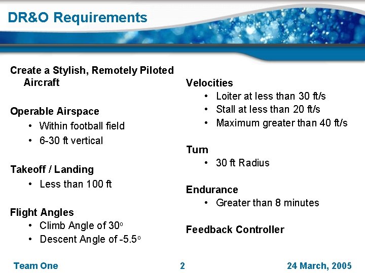
DR&O Requirements Create a Stylish, Remotely Piloted Aircraft Velocities • Loiter at less than 30 ft/s • Stall at less than 20 ft/s Operable Airspace • Maximum greater than 40 ft/s • Within football field • 6 -30 ft vertical Turn • 30 ft Radius Takeoff / Landing • Less than 100 ft Endurance • Greater than 8 minutes Flight Angles • Climb Angle of 30 o • Descent Angle of -5. 5 o Team One Feedback Controller 2 24 March, 2005
Design Concept Team One 3 24 March, 2005
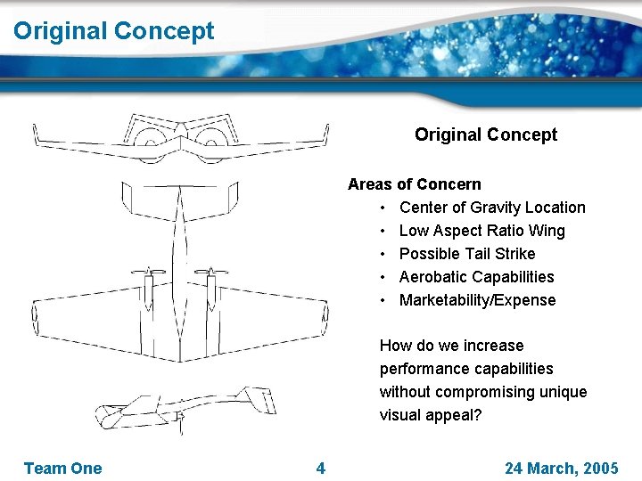
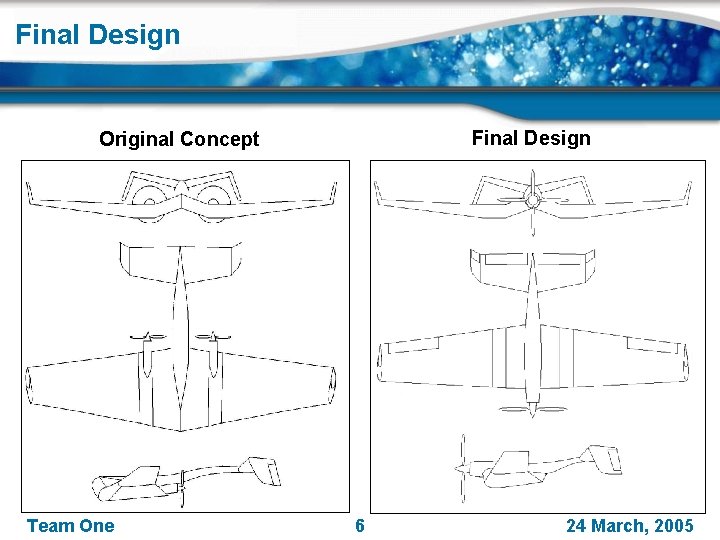
Original Concept Areas of Concern • Center of Gravity Location • Low Aspect Ratio Wing • Possible Tail Strike • Aerobatic Capabilities • Marketability/Expense How do we increase performance capabilities without compromising unique visual appeal? Team One 4 24 March, 2005
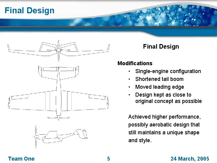
Final Design Modifications • Single-engine configuration • Shortened tail boom • Moved leading edge • Design kept as close to original concept as possible Achieved higher performance, possibly aerobatic design that still maintains a unique shape and style. Team One 5 24 March, 2005
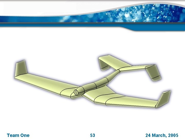
Final Design Original Concept Team One 6 24 March, 2005
Style Features Tapered wing planform • Provides appealing look Unique polyhedral wing design • Combines distinctive visual styling cues Winglets • Provide finished look to polyhedral theme Hybrid fuselage/boom structure • Creates distinctive profile Polyhedral tail design • Maintains consistency of aircraft appearance Team One 7 24 March, 2005
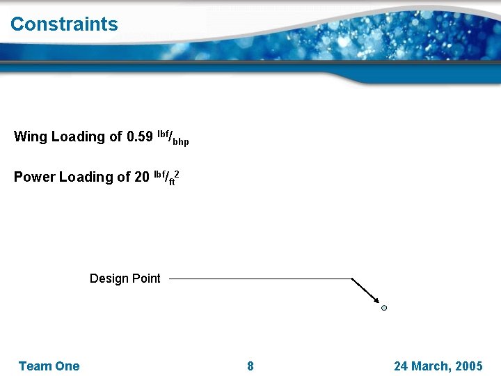
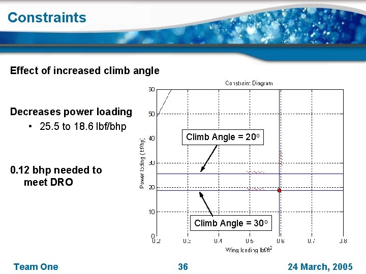
Constraints Wing Loading of 0. 59 lbf/bhp Power Loading of 20 lbf/ft 2 Design Point Team One 8 24 March, 2005
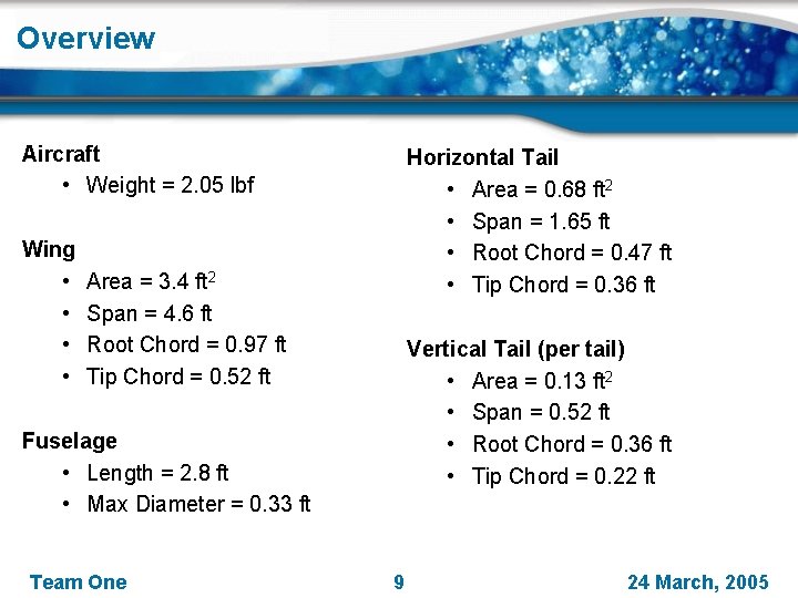
Overview Aircraft • Weight = 2. 05 lbf Wing • • Horizontal Tail • Area = 0. 68 ft 2 • Span = 1. 65 ft • Root Chord = 0. 47 ft • Tip Chord = 0. 36 ft Area = 3. 4 ft 2 Span = 4. 6 ft Root Chord = 0. 97 ft Tip Chord = 0. 52 ft Vertical Tail (per tail) • Area = 0. 13 ft 2 • Span = 0. 52 ft • Root Chord = 0. 36 ft • Tip Chord = 0. 22 ft Fuselage • Length = 2. 8 ft • Max Diameter = 0. 33 ft Team One 9 24 March, 2005
Aerodynamics Team One 10 24 March, 2005
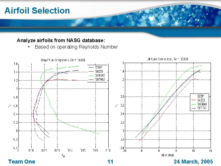
Airfoil Selection Analyze airfoils from NASG database: • Based on operating Reynolds Number Team One 11 24 March, 2005
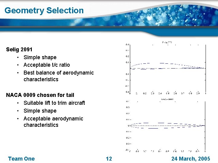
Geometry Selection Selig 2091 • Simple shape • Acceptable t/c ratio • Best balance of aerodynamic characteristics NACA 0009 chosen for tail • Suitable lift to trim aircraft • Simple shape • Acceptable aerodynamic characteristics Team One 12 24 March, 2005
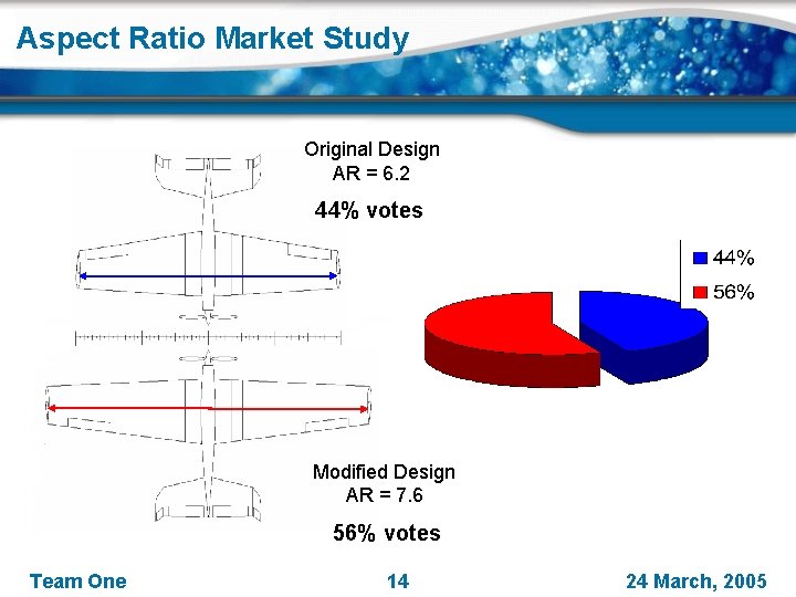
Market Study How to balance ‘style’ versus aerodynamic performance? Market Study • Sampled 25 random people on style parameters • • • Sweep Angle Aspect Ratio Dihedral Angle Taper Ratio Winglets Weighted Market Study versus Aerodynamics Team One 13 24 March, 2005
Aspect Ratio Market Study Original Design AR = 6. 2 44% votes Modified Design AR = 7. 6 56% votes Team One 14 24 March, 2005
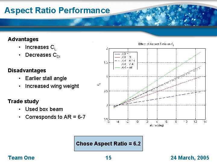
Aspect Ratio Performance Advantages • Increases CL • Decreases CDi Disadvantages • Earlier stall angle • Increased wing weight Trade study • Used box beam • Corresponds to AR = 6 -7 Chose Aspect Ratio = 6. 2 Team One 15 24 March, 2005
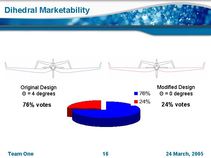
Dihedral Marketability Original Design Θ = 4 degrees Modified Design Θ = 0 degrees 76% votes 24% votes Team One 16 24 March, 2005
Dihedral Angle Polyhedral Wing Design • Dihedral Angle measured using Effective V-Dihedral Method (EVD) • Wing Taper also affects EVD • Self corrects roll For Aerobatic aircraft typical • EVD = 0°- 2° EVD = 3. 0° A = -25° B = 25° C = 4. 5° x 1 = 0. 18 (ratio of wing span) x 2 = 0. 32 (ratio of wing span) Market Study suggests EVD = 4° Chose EVD = 3° Team One 17 24 March, 2005
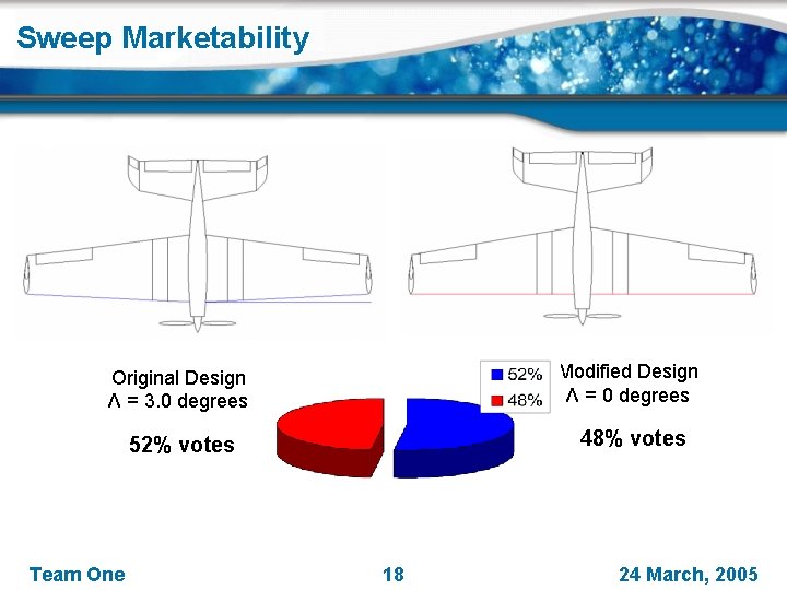
Sweep Marketability Original Design Λ = 3. 0 degrees Modified Design Λ = 0 degrees 52% votes 48% votes Team One 18 24 March, 2005
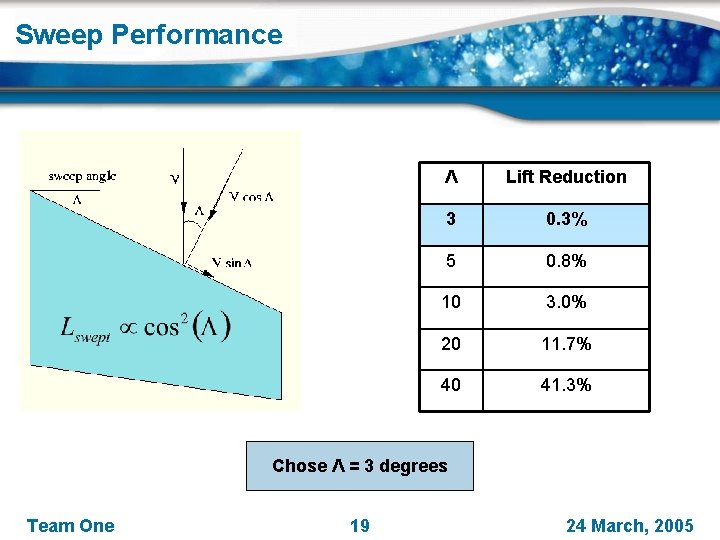
Sweep Performance Λ Lift Reduction 3 0. 3% 5 0. 8% 10 3. 0% 20 11. 7% 40 41. 3% Chose Λ = 3 degrees Team One 19 24 March, 2005
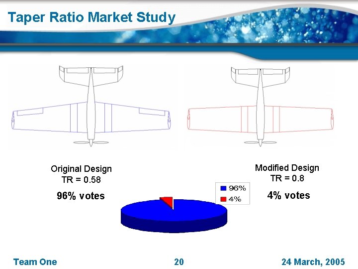
Taper Ratio Market Study Original Design TR = 0. 58 Modified Design TR = 0. 8 96% votes 4% votes Team One 20 24 March, 2005
Taper Ratio Performance Brings planform closer to an elliptical shape Desire λ = 0. 4 - 0. 5 Increases AR, decreases area Chose λ = 0. 5 Team One 21 24 March, 2005
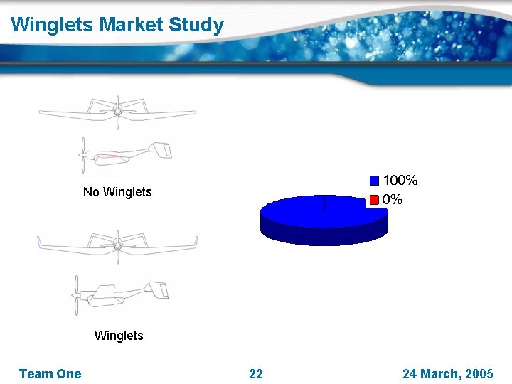
Winglets Market Study No Winglets Team One 22 24 March, 2005
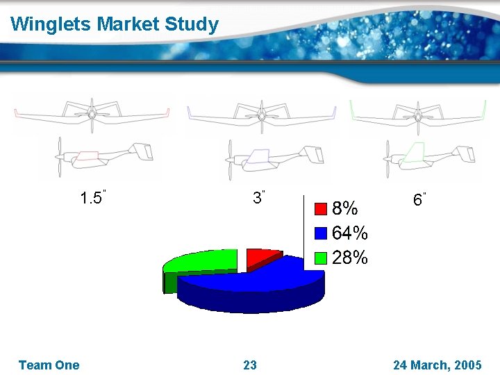
Winglets Market Study 1. 5” Team One 3” 23 6” 24 March, 2005
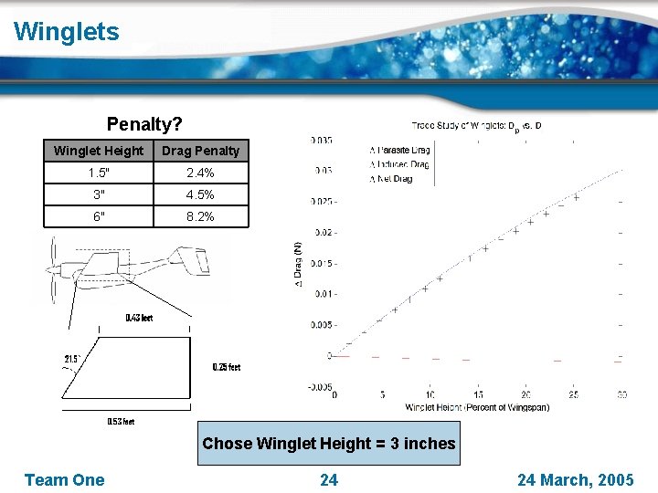
Winglets Penalty? Winglet Height Drag Penalty 1. 5" 2. 4% 3" 4. 5% 6" 8. 2% Chose Winglet Height = 3 inches Team One 24 March, 2005
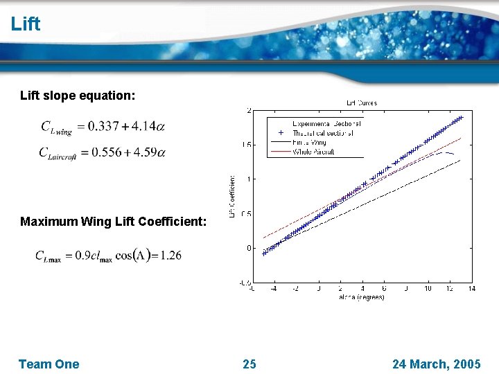
Lift slope equation: Maximum Wing Lift Coefficient: Team One 25 24 March, 2005
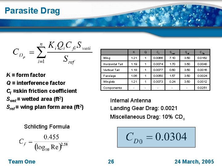
Parasite Drag K = form factor Q = interference factor Cf =skin friction coefficient Swet = wetted area (ft 2) Sref = wing plan form area (ft 2) K Q Cf Swet Sref CDp Wing 1. 21 1 0. 0066 7. 10 3. 50 0. 0162 Horizontal Tail 1. 19 1 0. 0074 1. 70 3. 50 0. 0043 Vertical Tail 1. 18 1 0. 0077 0. 60 3. 50 0. 0016 Fuselage 1. 06 1 0. 0050 1. 57 3. 50 0. 0024 Winglets 1. 21 1 0. 0073 0. 24 3. 50 0. 0012 - - - 0. 0251 Components Internal Antenna Landing Gear Drag: 0. 0021 Miscellaneous Drag: 10% CDo Schlicting Formula Team One 26 24 March, 2005
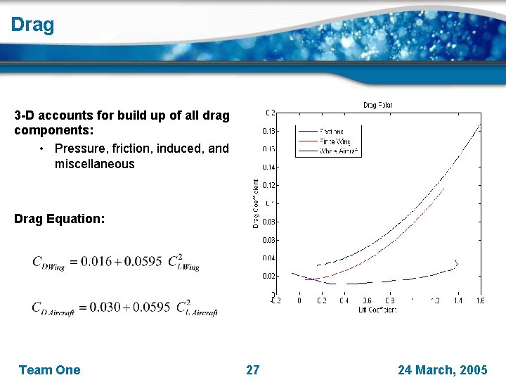
Drag 3 -D accounts for build up of all drag components: • Pressure, friction, induced, and miscellaneous Drag Equation: Team One 27 24 March, 2005
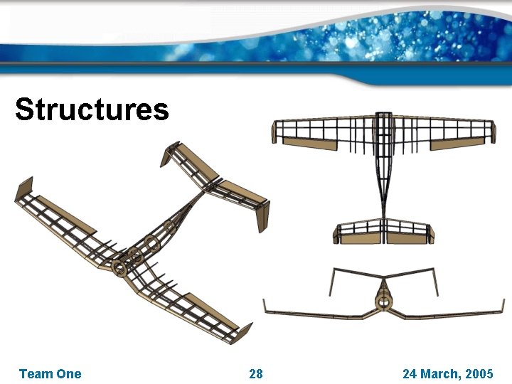
Structures Team One 28 24 March, 2005
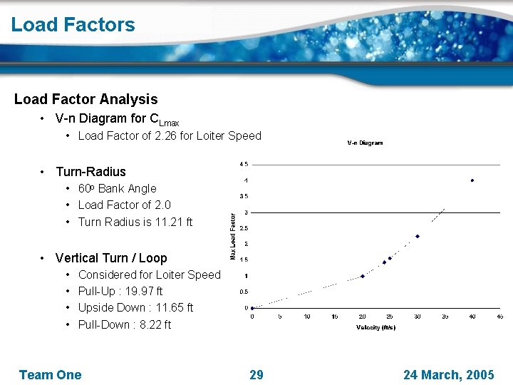
Load Factors Load Factor Analysis • V-n Diagram for CLmax • Load Factor of 2. 26 for Loiter Speed • Turn-Radius • 60 o Bank Angle • Load Factor of 2. 0 • Turn Radius is 11. 21 ft • Vertical Turn / Loop • • Considered for Loiter Speed Pull-Up : 19. 97 ft Upside Down : 11. 65 ft Pull-Down : 8. 22 ft Team One 29 24 March, 2005
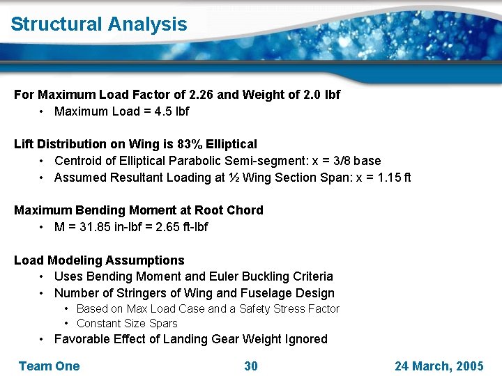
Structural Analysis For Maximum Load Factor of 2. 26 and Weight of 2. 0 lbf • Maximum Load = 4. 5 lbf Lift Distribution on Wing is 83% Elliptical • Centroid of Elliptical Parabolic Semi-segment: x = 3/8 base • Assumed Resultant Loading at ½ Wing Section Span: x = 1. 15 ft Maximum Bending Moment at Root Chord • M = 31. 85 in-lbf = 2. 65 ft-lbf Load Modeling Assumptions • Uses Bending Moment and Euler Buckling Criteria • Number of Stringers of Wing and Fuselage Design • Based on Max Load Case and a Safety Stress Factor • Constant Size Spars • Favorable Effect of Landing Gear Weight Ignored Team One 30 24 March, 2005
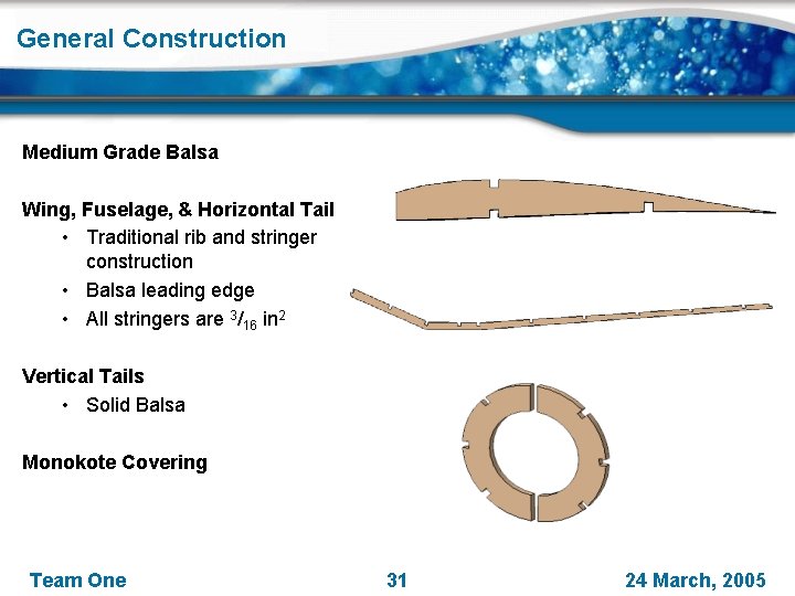
General Construction Medium Grade Balsa Wing, Fuselage, & Horizontal Tail • Traditional rib and stringer construction • Balsa leading edge • All stringers are 3/16 in 2 Vertical Tails • Solid Balsa Monokote Covering Team One 31 24 March, 2005
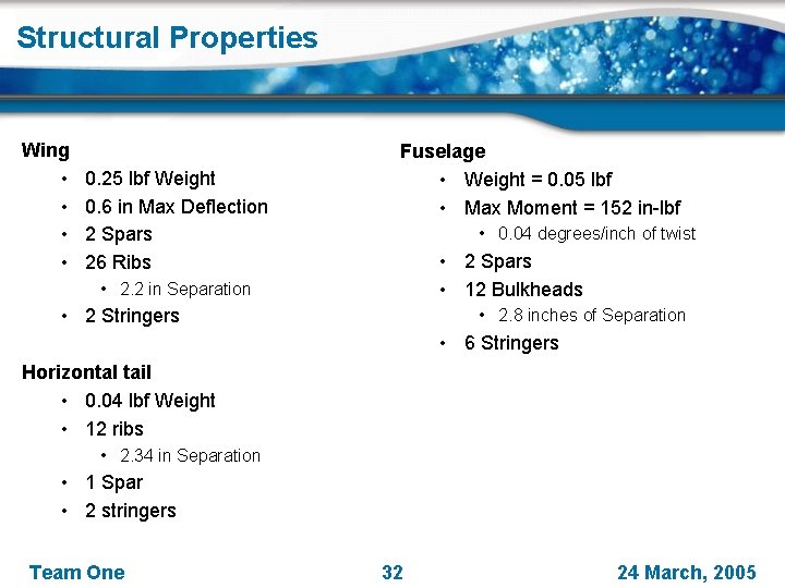
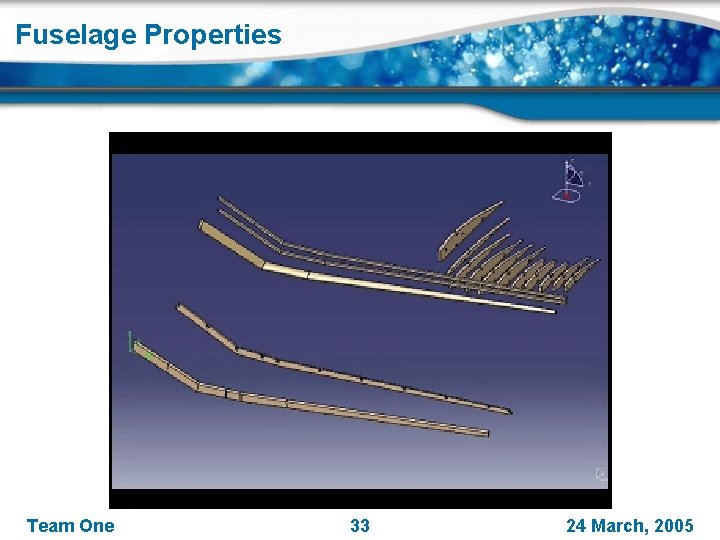
Structural Properties Wing • • 0. 25 lbf Weight 0. 6 in Max Deflection 2 Spars 26 Ribs Fuselage • Weight = 0. 05 lbf • Max Moment = 152 in-lbf • 0. 04 degrees/inch of twist • 2 Spars • 12 Bulkheads • 2. 2 in Separation • 2 Stringers • 2. 8 inches of Separation • 6 Stringers Horizontal tail • 0. 04 lbf Weight • 12 ribs • 2. 34 in Separation • 1 Spar • 2 stringers Team One 32 24 March, 2005
Fuselage Properties Team One 33 24 March, 2005
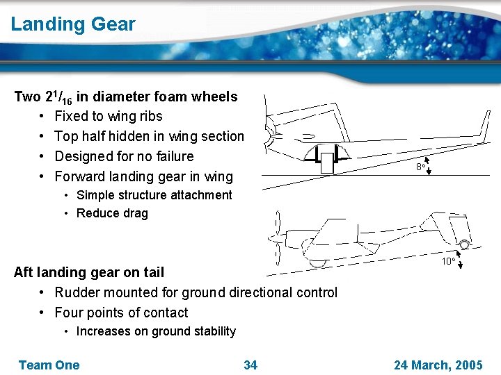
Landing Gear Two 21/16 in diameter foam wheels • Fixed to wing ribs • Top half hidden in wing section • Designed for no failure • Forward landing gear in wing 8 o • Simple structure attachment • Reduce drag Aft landing gear on tail • Rudder mounted for ground directional control • Four points of contact 10 o • Increases on ground stability Team One 34 24 March, 2005
Propulsion Team One 35 24 March, 2005
Constraints Effect of increased climb angle Decreases power loading • 25. 5 to 18. 6 lbf/bhp Climb Angle = 20 o 0. 12 bhp needed to meet DRO Climb Angle = 30 o Team One 36 24 March, 2005
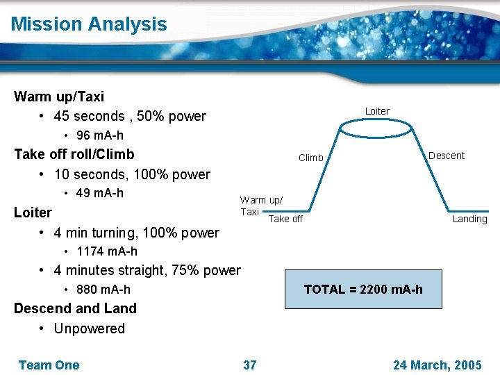
Mission Analysis Warm up/Taxi • 45 seconds , 50% power Loiter • 96 m. A-h Take off roll/Climb • 10 seconds, 100% power • 49 m. A-h Loiter • 4 min turning, 100% power Descent Climb Warm up/ Taxi Take off Landing • 1174 m. A-h • 4 minutes straight, 75% power • 880 m. A-h TOTAL = 2200 m. A-h Descend and Land • Unpowered Team One 37 24 March, 2005
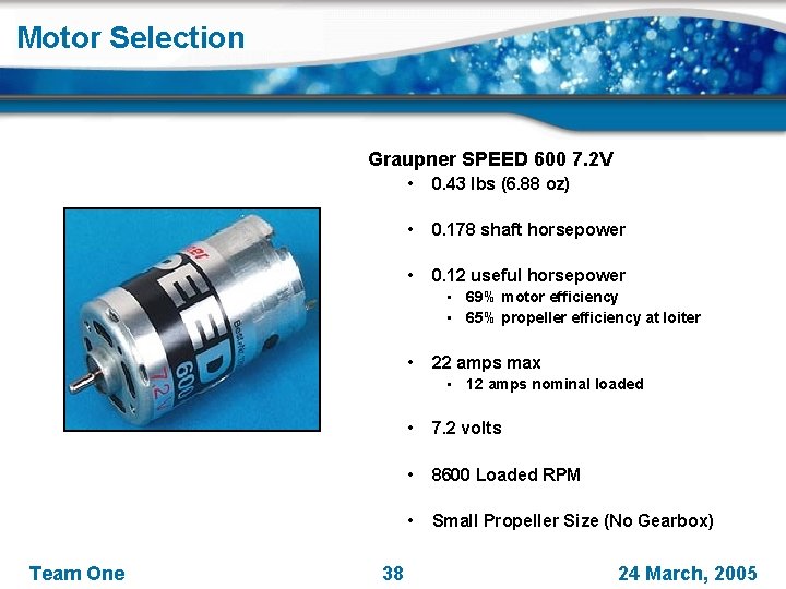
Motor Selection Graupner SPEED 600 7. 2 V • 0. 43 lbs (6. 88 oz) • 0. 178 shaft horsepower • 0. 12 useful horsepower • 69% motor efficiency • 65% propeller efficiency at loiter • 22 amps max • 12 amps nominal loaded Team One 38 • 7. 2 volts • 8600 Loaded RPM • Small Propeller Size (No Gearbox) 24 March, 2005
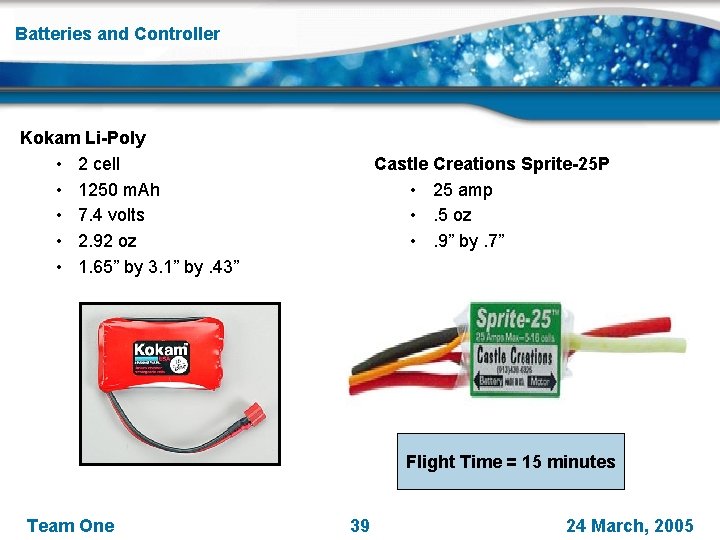
Batteries and Controller Kokam Li-Poly • 2 cell • 1250 m. Ah • 7. 4 volts • 2. 92 oz • 1. 65” by 3. 1” by. 43” Castle Creations Sprite-25 P • 25 amp • . 5 oz • . 9” by. 7” Flight Time = 15 minutes Team One 39 24 March, 2005
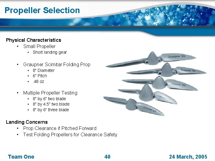
Propeller Selection Physical Characteristics • Small Propeller • Short landing gear • Graupner Scimitar Folding Prop • 8” Diameter • 6” Pitch • . 48 oz • Multiple Propeller Testing • 8” by 6” two blade • 8” by 4. 5” two blade • 8” by 6” three blade Landing Concerns • Prop Clearance if Pitched Forward • Test Folding Propellers for Clearance Safety Team One 40 24 March, 2005
Dynamics & Controls Team One 41 24 March, 2005
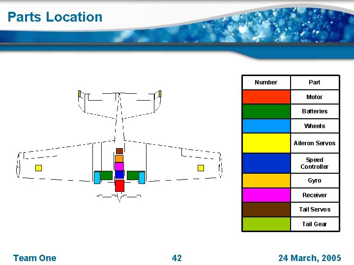
Parts Location Number Part Motor Batteries Wheels Aileron Servos Speed Controller Gyro Receiver Tail Servos Tail Gear Team One 42 24 March, 2005
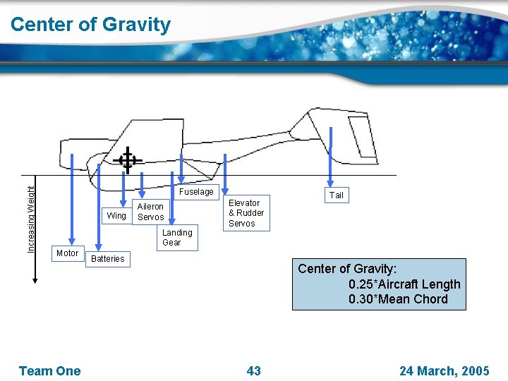
Increasing Weight Center of Gravity Fuselage Wing Aileron Servos Landing Gear Motor Team One Elevator & Rudder Servos Batteries Tail Center of Gravity: 0. 25*Aircraft Length 0. 30*Mean Chord 43 24 March, 2005
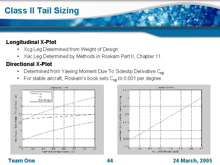
Class II Tail Sizing Longitudinal X-Plot • • Xcg Leg Determined from Weight of Design Xac Leg Determined by Methods in Roskam Part II, Chapter 11 Directional X-Plot • • Determined from Yawing Moment Due To Sideslip Derivative Cnβ For stable aircraft, Roskam’s book sets Cnβ to 0. 001 per degree. Team One 44 24 March, 2005
Tail Sizing Roskam method implemented in code • Determined By Coefficient Ratio Equation • Static Margin = 12. 63% AC CG Team One 45 24 March, 2005
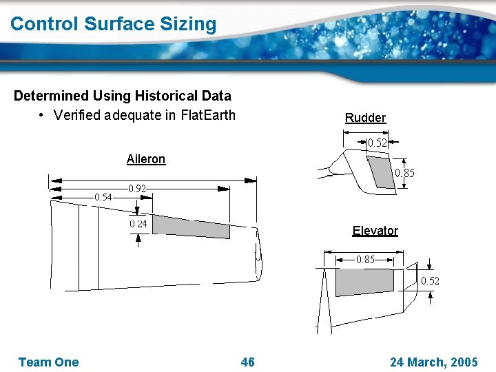
Control Surface Sizing Determined Using Historical Data • Verified adequate in Flat. Earth Rudder Aileron Elevator Team One 46 24 March, 2005
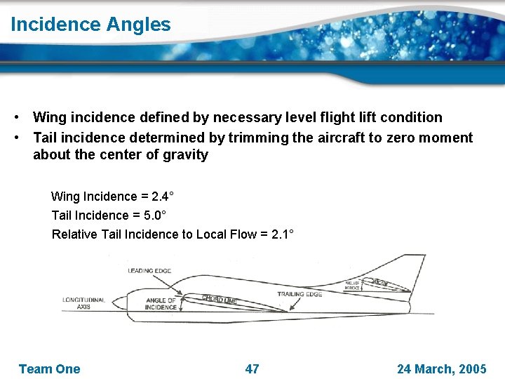
Incidence Angles • Wing incidence defined by necessary level flight lift condition • Tail incidence determined by trimming the aircraft to zero moment about the center of gravity Wing Incidence = 2. 4° Tail Incidence = 5. 0° Relative Tail Incidence to Local Flow = 2. 1° Team One 47 24 March, 2005
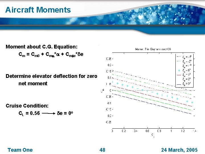
Aircraft Moments Moment about C. G. Equation: Cm = Cm 0 + Cma*a + Cmde*de Determine elevator deflection for zero net moment Cruise Condition: CL = 0. 56 de = 0 o Team One 48 24 March, 2005
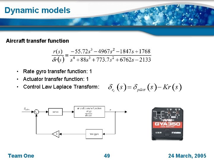
Dynamic models Aircraft transfer function • Rate gyro transfer function: 1 • Actuator transfer function: 1 • Control Law Laplace Transform: Team One 49 24 March, 2005
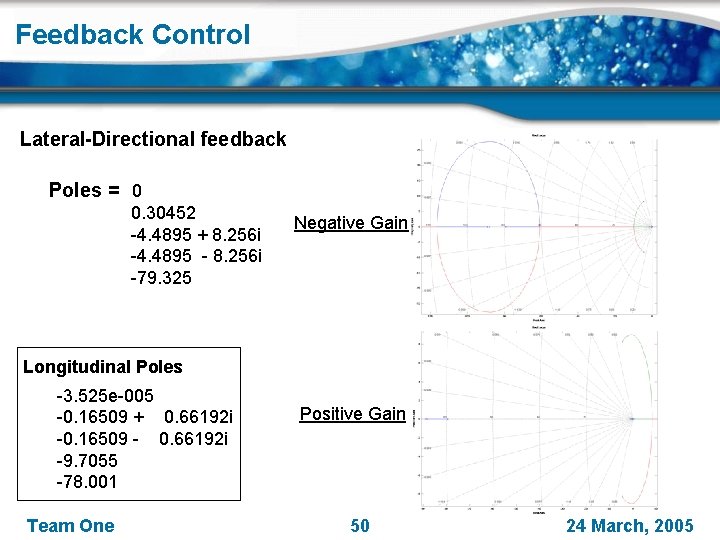
Feedback Control Lateral-Directional feedback Poles = 0 0. 30452 -4. 4895 + 8. 256 i -4. 4895 - 8. 256 i -79. 325 Negative Gain Longitudinal Poles -3. 525 e-005 -0. 16509 + 0. 66192 i -0. 16509 - 0. 66192 i -9. 7055 -78. 001 Team One Positive Gain 50 24 March, 2005
Design Code Team One 51 24 March, 2005
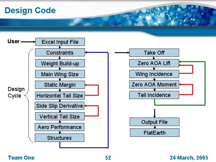
Design Code User Design Cycle Excel Input File Constraints Take Off Weight Build-up Zero AOA Lift Main Wing Size Wing Incidence Static Margin Zero AOA Moment Horizontal Tail Size Tail Incidence Side Slip Derivative Vertical Tail Size Output File Aero Performance Flat. Earth Structures Team One 52 24 March, 2005
Team One 53 24 March, 2005