
CRITICAL DESIGN REVIEW CDR Charger Rocket Works University

- Slides: 69
CRITICAL DESIGN REVIEW (CDR) Charger Rocket Works University of Alabama in Huntsville NASA Student Launch 2013 -14 Kenneth Le. Blanc (Project Lead) Brian Roy (Safety Officer) Chris Spalding (Design Lead) Chad O’Brien (Analysis Lead) Wesley Cobb (Payload Lead)
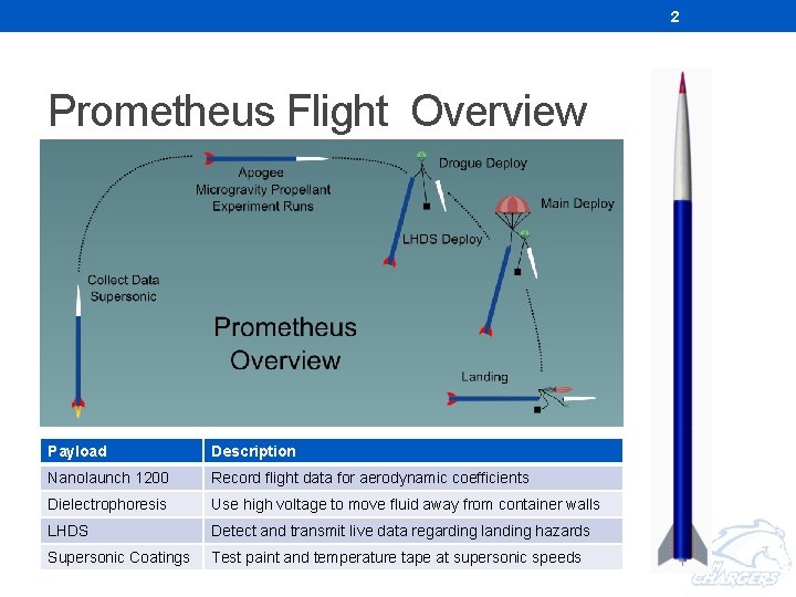
2 Prometheus Flight Overview Payload Description Nanolaunch 1200 Record flight data for aerodynamic coefficients Dielectrophoresis LHDS Supersonic Coatings Use high voltage to move fluid away from container walls Payloads Here Detect and transmit live data regarding landing hazards Test paint and temperature tape at supersonic speeds
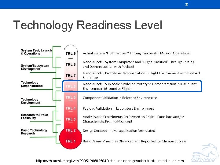
3 Technology Readiness Level http: //web. archive. org/web/20051206035043/http: //as. nasa. gov/aboutus/trl-introduction. html
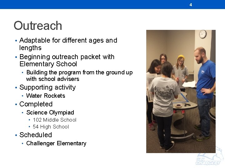
4 Outreach • Adaptable for different ages and lengths • Beginning outreach packet with Elementary School • Building the program from the ground up with school advisers • Supporting activity • Water Rockets • Completed • Science Olympiad • 102 Middle School • 54 High School • Scheduled • Challenger Elementary
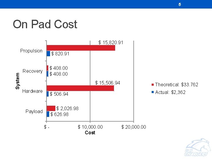
5 On Pad Cost $ 15, 820. 91 System Propulsion Recovery $ 820. 91 $ 408. 00 $ 15, 506. 94 Hardware Theoretical: $33. 762 Actual: $2, 362 $ 506. 94 $ 2, 026. 98 $ 626. 98 Payload $- $ 10, 000. 00 Cost $ 20, 000. 00
6 ANALYSIS
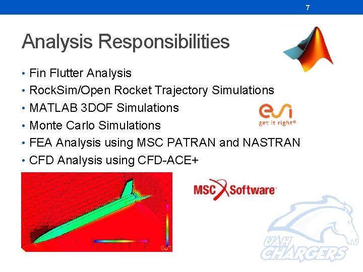
7 Analysis Responsibilities • Fin Flutter Analysis • Rock. Sim/Open Rocket Trajectory Simulations • MATLAB 3 DOF Simulations • Monte Carlo Simulations • FEA Analysis using MSC PATRAN and NASTRAN • CFD Analysis using CFD-ACE+
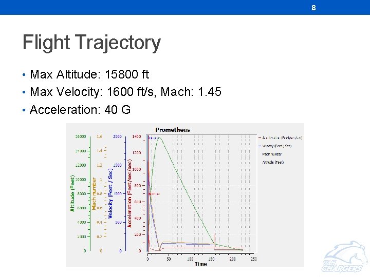
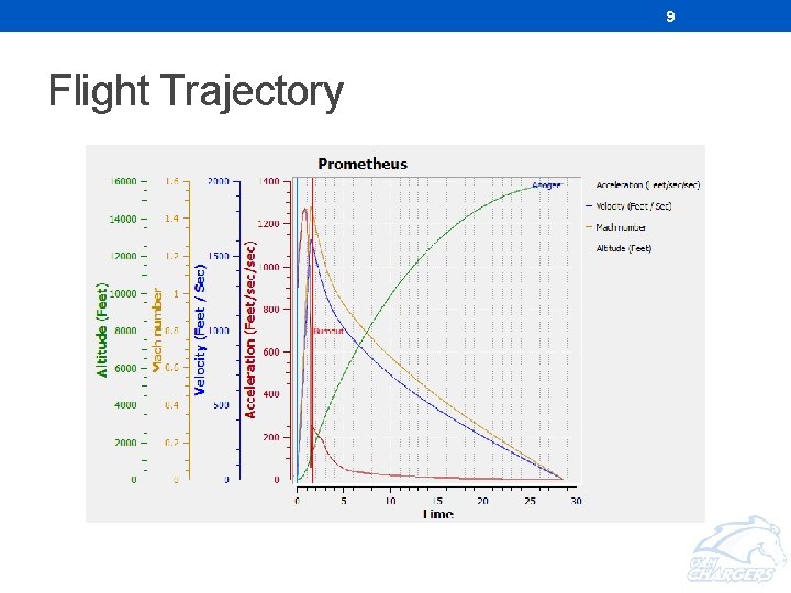
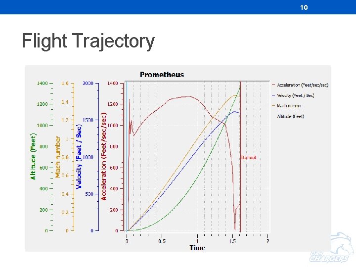
8 Flight Trajectory • Max Altitude: 15800 ft • Max Velocity: 1600 ft/s, Mach: 1. 45 • Acceleration: 40 G
9 Flight Trajectory
10 Flight Trajectory
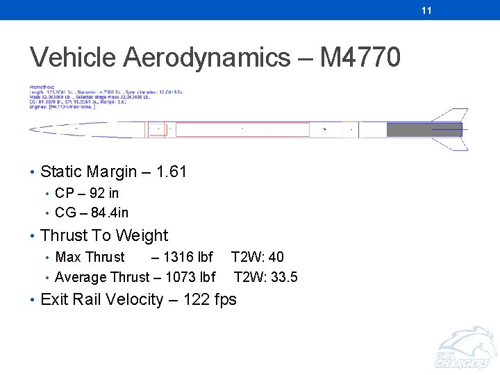
11 Vehicle Aerodynamics – M 4770 • Static Margin – 1. 61 • CP – 92 in • CG – 84. 4 in • Thrust To Weight • Max Thrust – 1316 lbf • Average Thrust – 1073 lbf T 2 W: 40 T 2 W: 33. 5 • Exit Rail Velocity – 122 fps
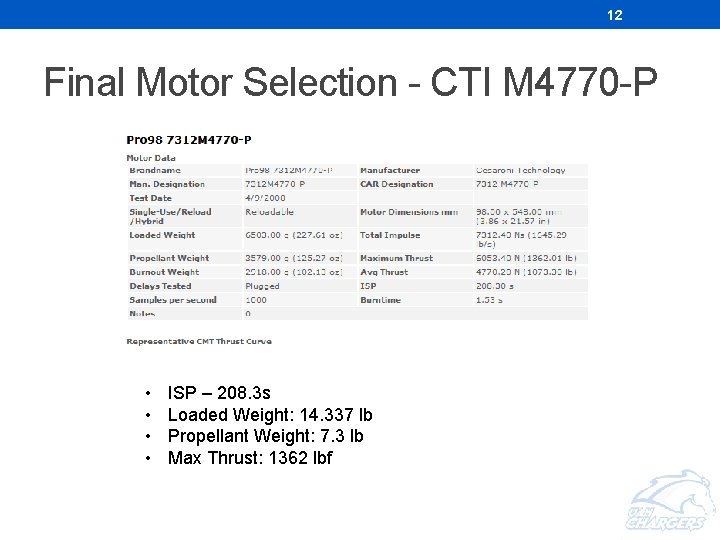
12 Final Motor Selection - CTI M 4770 -P • • ISP – 208. 3 s Loaded Weight: 14. 337 lb Propellant Weight: 7. 3 lb Max Thrust: 1362 lbf
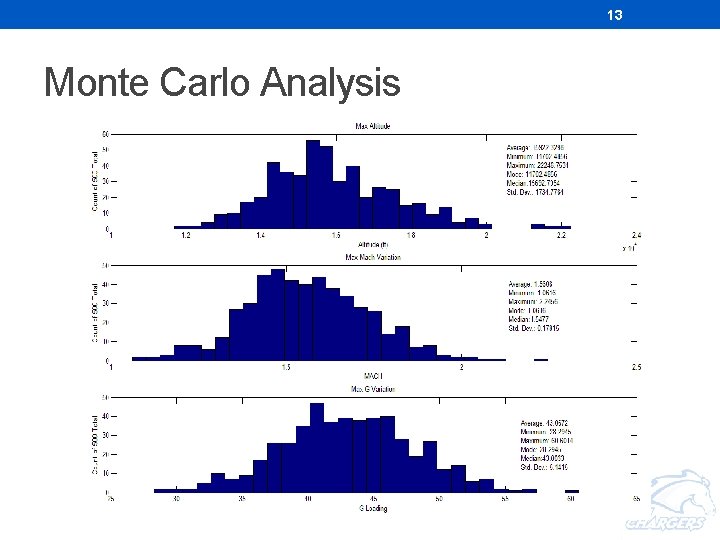
13 Monte Carlo Analysis
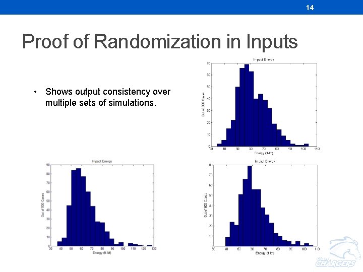
14 Proof of Randomization in Inputs • Shows output consistency over multiple sets of simulations.
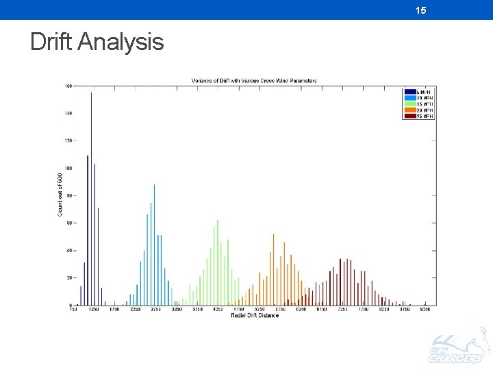
15 Drift Analysis
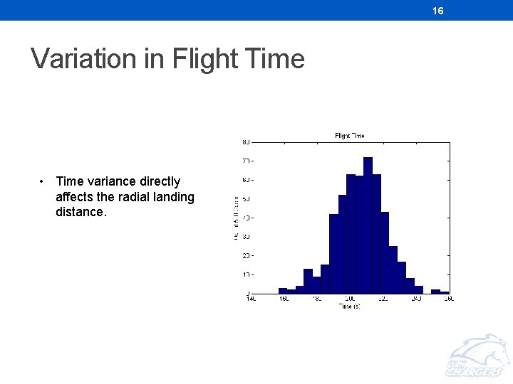
16 Variation in Flight Time • Time variance directly affects the radial landing distance.
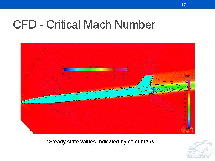
17 CFD - Critical Mach Number *Steady state values Indicated by color maps
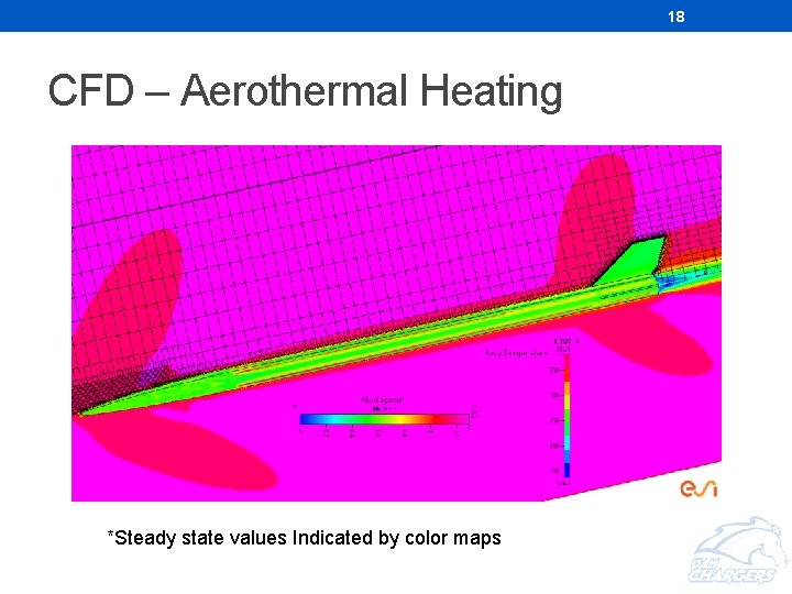
18 CFD – Aerothermal Heating *Steady state values Indicated by color maps
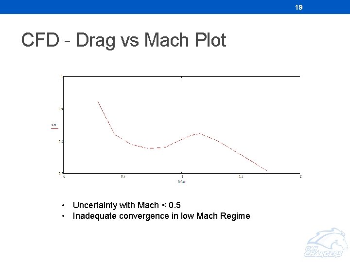
19 CFD - Drag vs Mach Plot • Uncertainty with Mach < 0. 5 • Inadequate convergence in low Mach Regime
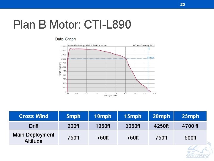
20 Plan B Motor: CTI-L 890 Cross Wind 5 mph 10 mph 15 mph 20 mph 25 mph Drift 900 ft 1950 ft 3050 ft 4250 ft 4700 ft Main Deployment Altitude 750 ft 500 ft
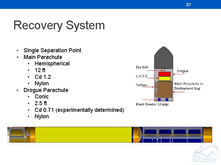
21 Recovery System • Single Separation Point • Main Parachute • Hemispherical • 12 ft • Cd 1. 2 • Nylon • Drogue Parachute • Conic • 2. 5 ft • Cd 0. 71 (experimentally determined) • Nylon
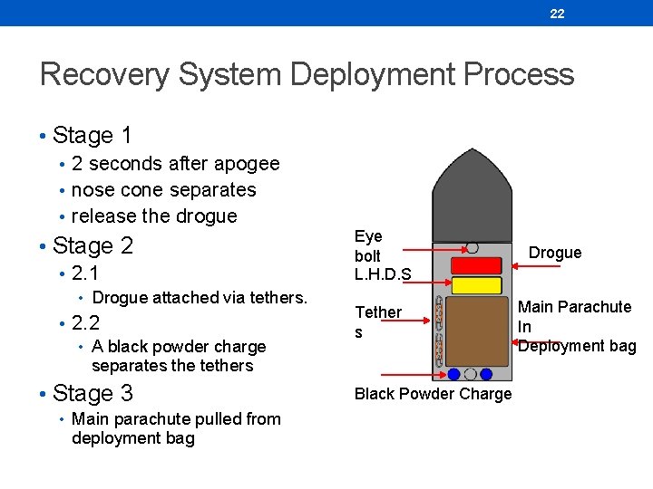
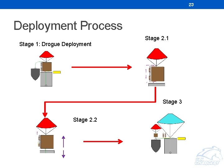
22 Recovery System Deployment Process • Stage 1 • 2 seconds after apogee • nose cone separates • release the drogue • Stage 2 • 2. 1 • Drogue attached via tethers. • 2. 2 • A black powder charge separates the tethers • Stage 3 • Main parachute pulled from deployment bag Eye bolt L. H. D. S Tether s Black Powder Charge Drogue Main Parachute In Deployment bag
23 Deployment Process Stage 1: Drogue Deployment Stage 2. 1 Stage 3 Stage 2. 2
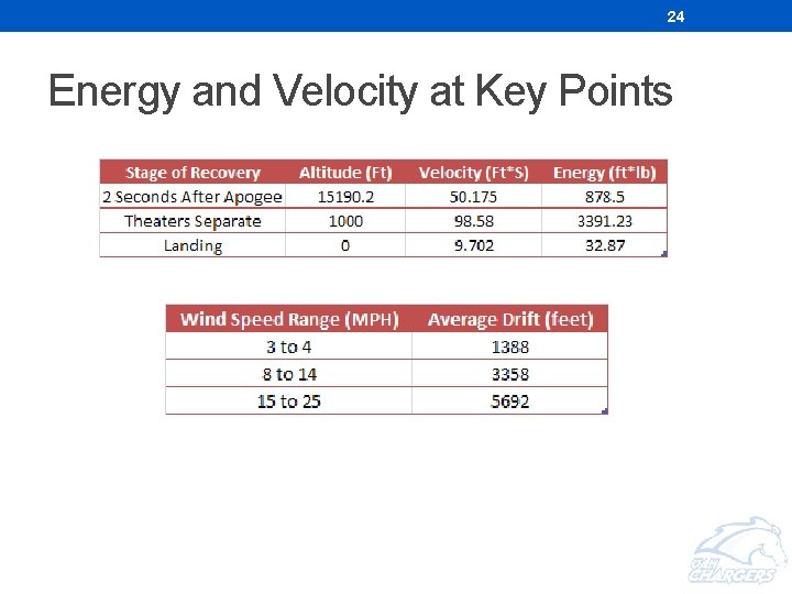
24 Energy and Velocity at Key Points
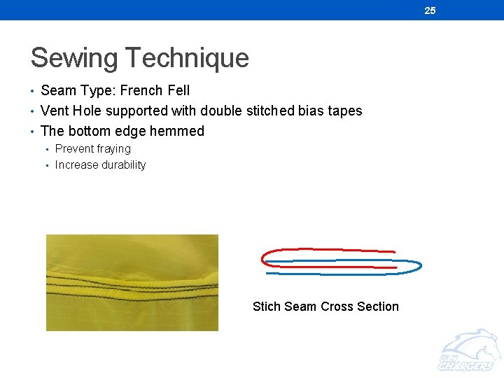
25 Sewing Technique • Seam Type: French Fell • Vent Hole supported with double stitched bias tapes • The bottom edge hemmed • Prevent fraying • Increase durability Stich Seam Cross Section
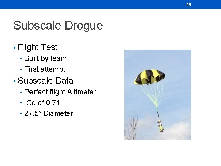
26 Subscale Drogue • Flight Test • Built by team • First attempt • Subscale Data • Perfect flight Altimeter • Cd of 0. 71 • 27. 5” Diameter
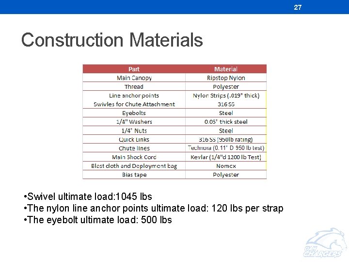
27 Construction Materials • Swivel ultimate load: 1045 lbs • The nylon line anchor points ultimate load: 120 lbs per strap • The eyebolt ultimate load: 500 lbs
28 DESIGN
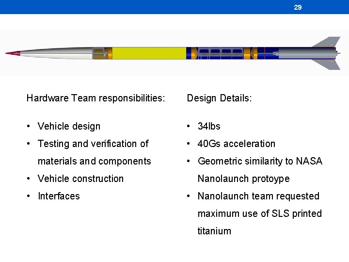
29 Hardware Team responsibilities: Design Details: • Vehicle design • 34 lbs • Testing and verification of • 40 Gs acceleration materials and components • Vehicle construction • Interfaces • Geometric similarity to NASA Nanolaunch protoype • Nanolaunch team requested maximum use of SLS printed titanium
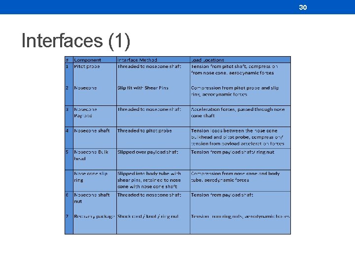
30 Interfaces (1)
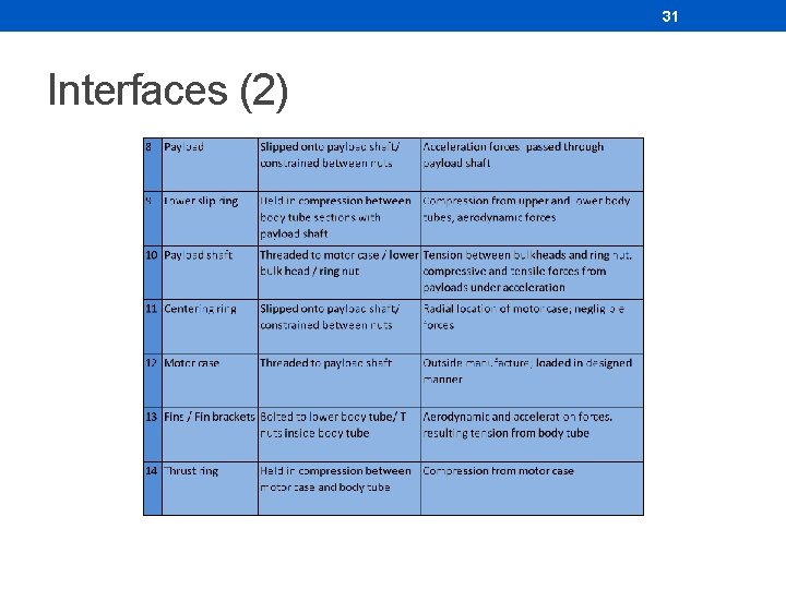
31 Interfaces (2)
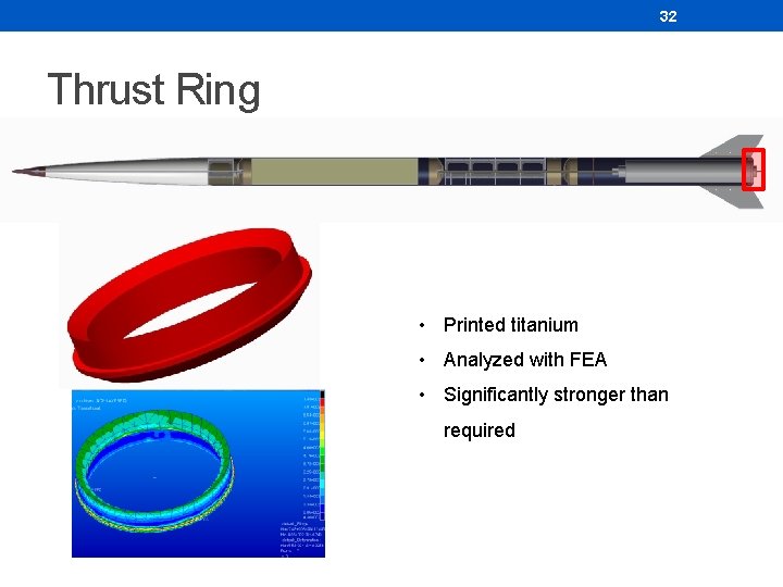
32 Thrust Ring • Printed titanium • Analyzed with FEA • Significantly stronger than required
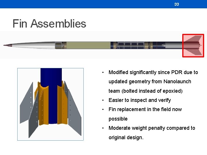
33 Fin Assemblies • Modified significantly since PDR due to updated geometry from Nanolaunch team (bolted instead of epoxied) • Easier to inspect and verify • Fin replacement in the field now possible • Moderate weight penalty compared to original design.
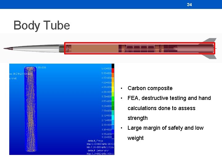
34 Body Tube • Carbon composite • FEA, destructive testing and hand calculations done to assess strength • Large margin of safety and low weight
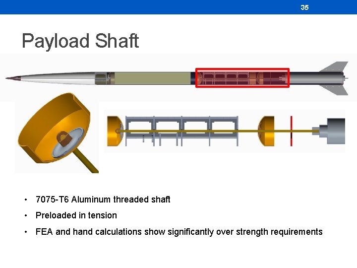
35 Payload Shaft • 7075 -T 6 Aluminum threaded shaft • Preloaded in tension • FEA and hand calculations show significantly over strength requirements
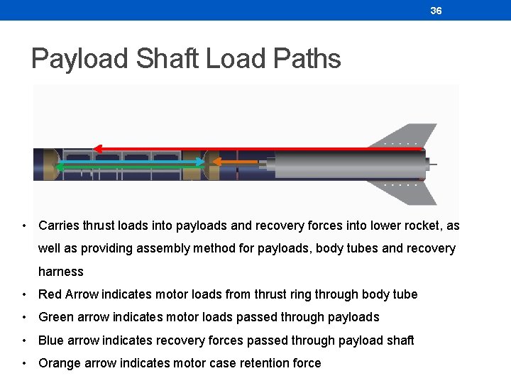
36 Payload Shaft Load Paths • Carries thrust loads into payloads and recovery forces into lower rocket, as well as providing assembly method for payloads, body tubes and recovery harness • Red Arrow indicates motor loads from thrust ring through body tube • Green arrow indicates motor loads passed through payloads • Blue arrow indicates recovery forces passed through payload shaft • Orange arrow indicates motor case retention force
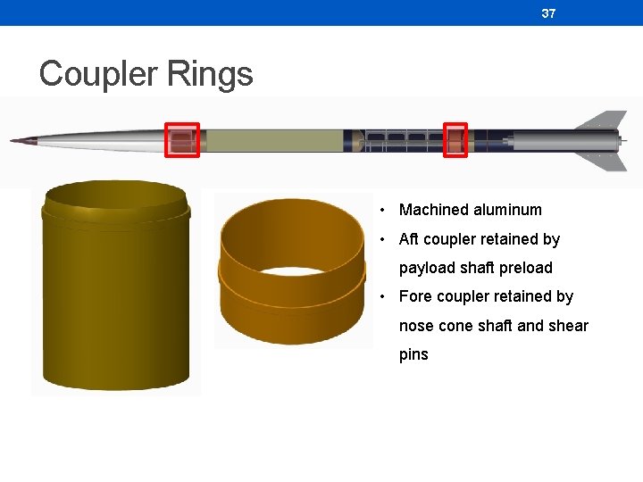
37 Coupler Rings • Machined aluminum • Aft coupler retained by payload shaft preload • Fore coupler retained by nose cone shaft and shear pins
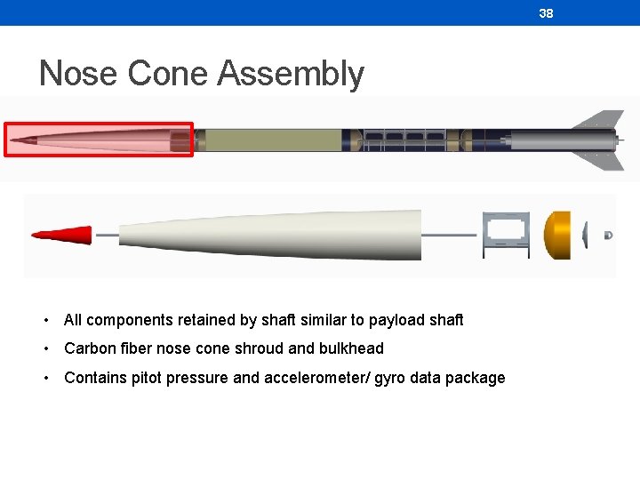
38 Nose Cone Assembly • All components retained by shaft similar to payload shaft • Carbon fiber nose cone shroud and bulkhead • Contains pitot pressure and accelerometer/ gyro data package
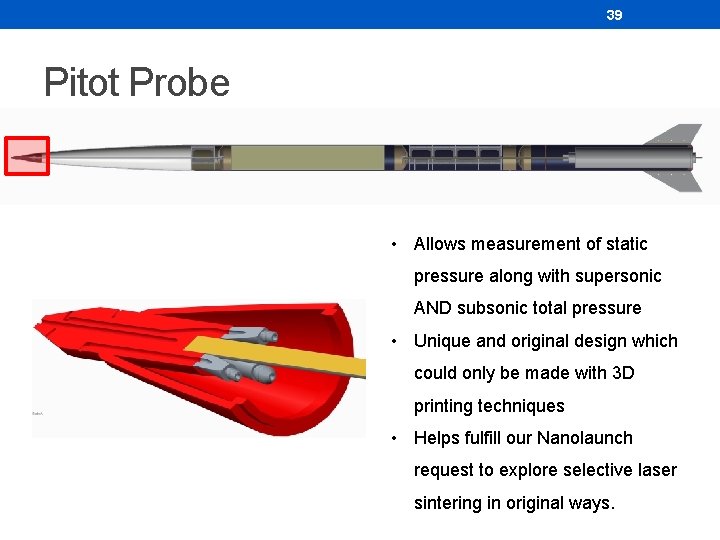
39 Pitot Probe • Allows measurement of static pressure along with supersonic AND subsonic total pressure • Unique and original design which could only be made with 3 D printing techniques • Helps fulfill our Nanolaunch request to explore selective laser sintering in original ways.
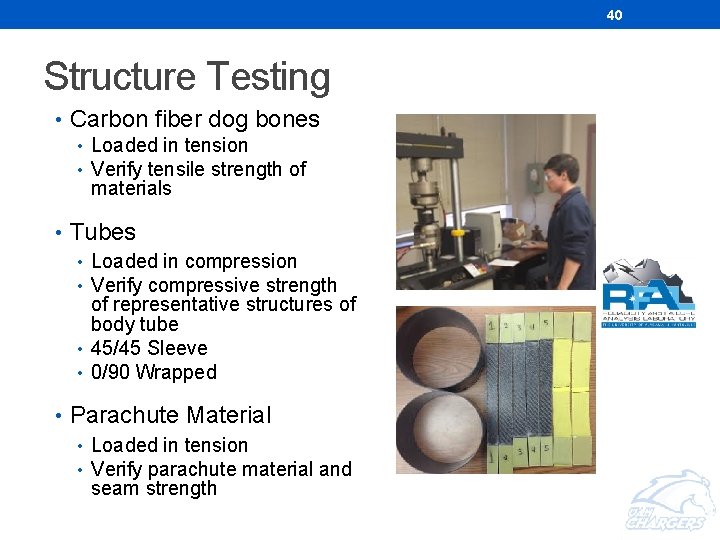
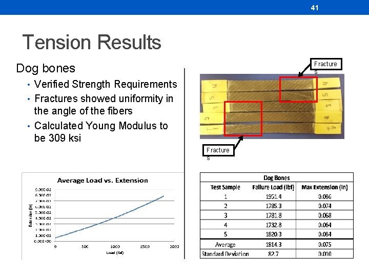
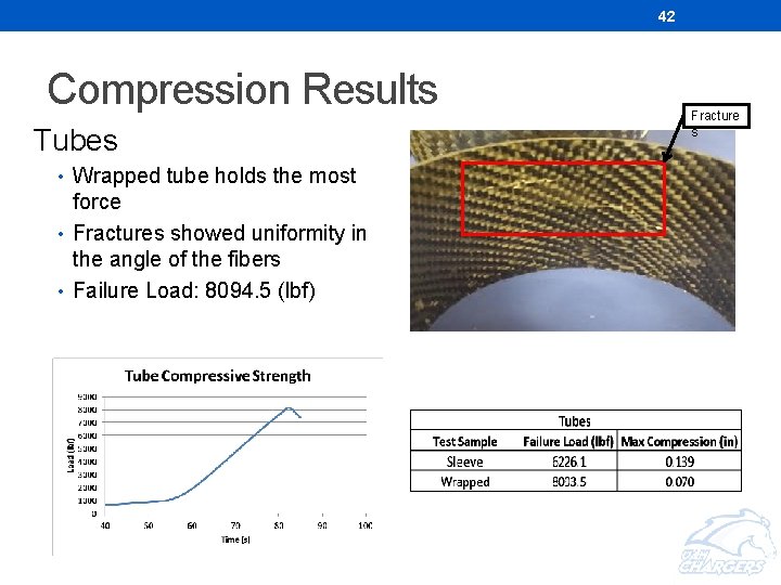
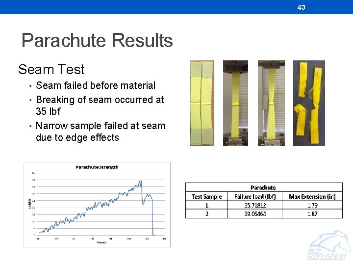
40 Structure Testing • Carbon fiber dog bones • Loaded in tension • Verify tensile strength of materials • Tubes • Loaded in compression • Verify compressive strength of representative structures of body tube • 45/45 Sleeve • 0/90 Wrapped • Parachute Material • Loaded in tension • Verify parachute material and seam strength
41 Tension Results Fracture s Dog bones • Verified Strength Requirements • Fractures showed uniformity in the angle of the fibers • Calculated Young Modulus to be 309 ksi Fracture s
42 Compression Results Tubes • Wrapped tube holds the most force • Fractures showed uniformity in the angle of the fibers • Failure Load: 8094. 5 (lbf) Fracture s
43 Parachute Results Seam Test • Seam failed before material • Breaking of seam occurred at 35 lbf • Narrow sample failed at seam due to edge effects
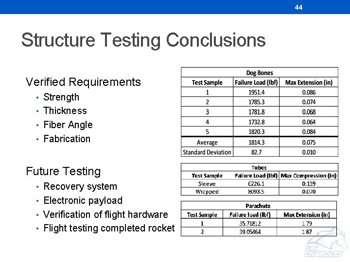
44 Structure Testing Conclusions Verified Requirements • Strength • Thickness • Fiber Angle • Fabrication Future Testing • Recovery system • Electronic payload • Verification of flight hardware • Flight testing completed rocket
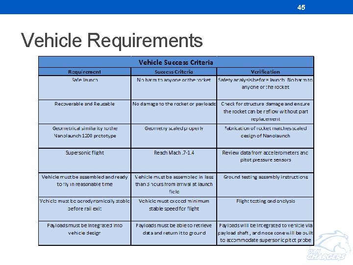
45 Vehicle Requirements
46 PROCEDURES
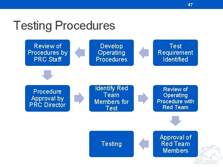
47 Testing Procedures Review of Procedures by PRC Staff Develop Operating Procedures Test Requirement Identified Procedure Approval by PRC Director Identify Red Team Members for Test Review of Operating Procedure with Red Team Testing Approval of Red Team Members
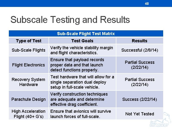
48 Subscale Testing and Results Sub-Scale Flight Test Matrix Type of Test Goals Results Sub-Scale Flights Verify the vehicle stability margin and flight characteristics. Successful (2/8/14) Flight Electronics Ensure that payload records proper data and that launch detect functions properly. Partial Success (2/22/14) Recovery System Hardware Test hardware that will allow for a single separation dual deploy setup in full-scale vehicle. Partial Success (2/22/14) Parachute Design Verify construction techniques are adequate and determine effective drag coefficient. High Acceleration Flight (40+ G’s) Ensure that avionics will survive launch forces of full-scale. Success (2/22/14) Not Yet Tested
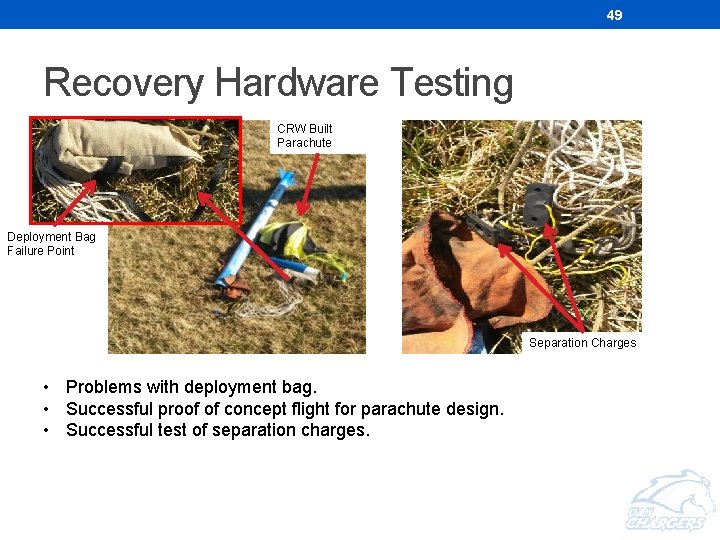
49 Recovery Hardware Testing CRW Built Parachute Deployment Bag Failure Point Separation Charges • Problems with deployment bag. • Successful proof of concept flight for parachute design. • Successful test of separation charges.
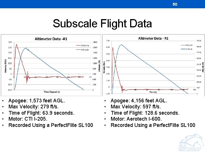
50 Subscale Flight Data • • • Apogee: 1, 573 feet AGL. Max Velocity: 279 ft/s. Time of Flight: 63. 9 seconds. Motor: CTI I-205. Recorded Using a Perfect. Flite SL 100 • • • Apogee: 4, 156 feet AGL. Max Velocity: 597 ft/s. Time of Flight: 128. 6 seconds. Motor: Aerotech I-600. Recorded Using a Perfect. Flite SL 100
51 PAYLOADS
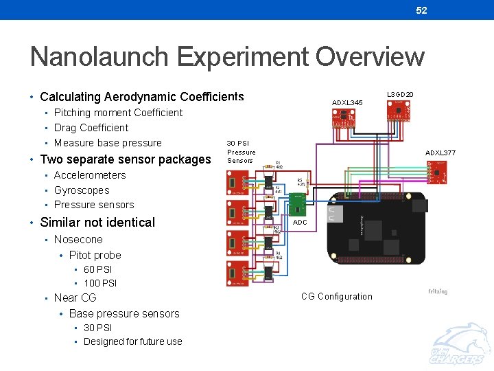
52 Nanolaunch Experiment Overview • Calculating Aerodynamic Coefficients L 3 GD 20 ADXL 345 • Pitching moment Coefficient • Drag Coefficient • Measure base pressure • Two separate sensor packages 30 PSI Pressure Sensors ADXL 377 • Accelerometers • Gyroscopes • Pressure sensors • Similar not identical ADC • Nosecone • Pitot probe • 60 PSI • 100 PSI • Near CG • Base pressure sensors • 30 PSI • Designed for future use CG Configuration
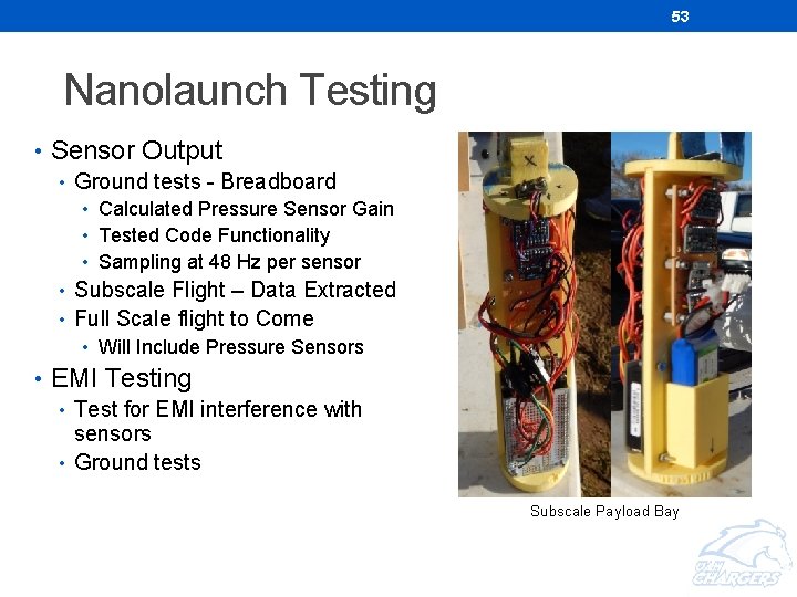
53 Nanolaunch Testing • Sensor Output • Ground tests - Breadboard • Calculated Pressure Sensor Gain • Tested Code Functionality • Sampling at 48 Hz per sensor • Subscale Flight – Data Extracted • Full Scale flight to Come • Will Include Pressure Sensors • EMI Testing • Test for EMI interference with sensors • Ground tests Subscale Payload Bay
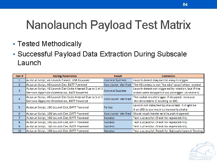
54 Nanolaunch Payload Test Matrix • Tested Methodically • Successful Payload Data Extraction During Subscale Launch
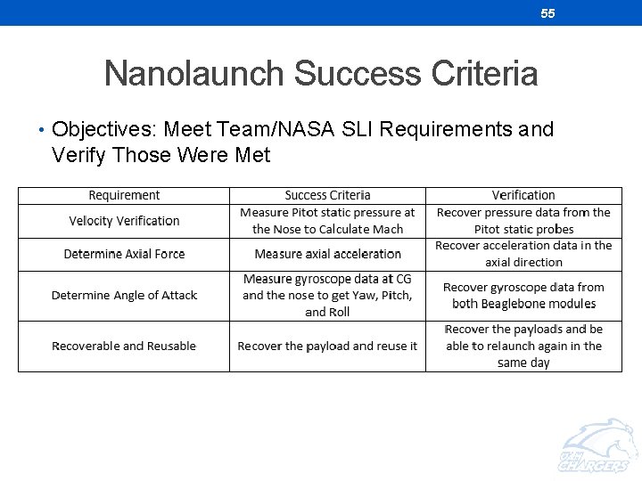
55 Nanolaunch Success Criteria • Objectives: Meet Team/NASA SLI Requirements and Verify Those Were Met
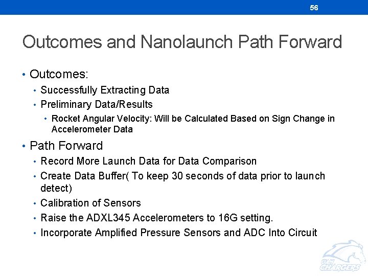
56 Outcomes and Nanolaunch Path Forward • Outcomes: • Successfully Extracting Data • Preliminary Data/Results • Rocket Angular Velocity: Will be Calculated Based on Sign Change in Accelerometer Data • Path Forward • Record More Launch Data for Data Comparison • Create Data Buffer( To keep 30 seconds of data prior to launch detect) • Calibration of Sensors • Raise the ADXL 345 Accelerometers to 16 G setting. • Incorporate Amplified Pressure Sensors and ADC Into Circuit
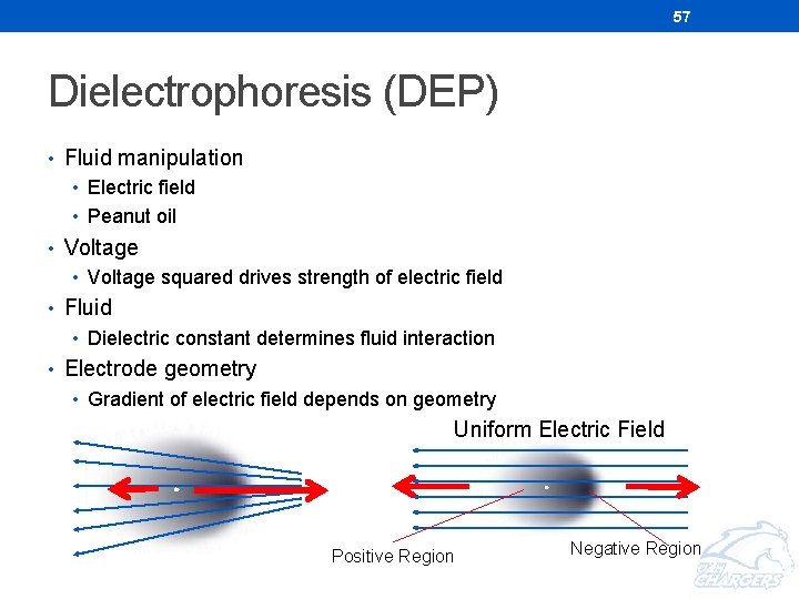
57 Dielectrophoresis (DEP) • Fluid manipulation • Electric field • Peanut oil • Voltage squared drives strength of electric field • Fluid • Dielectric constant determines fluid interaction • Electrode geometry • Gradient of electric field depends on geometry Uniform Electric Field Positive Region Negative Region
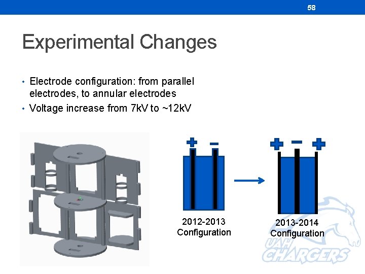
58 Experimental Changes • Electrode configuration: from parallel electrodes, to annular electrodes • Voltage increase from 7 k. V to ~12 k. V 2012 -2013 Configuration 2013 -2014 Configuration
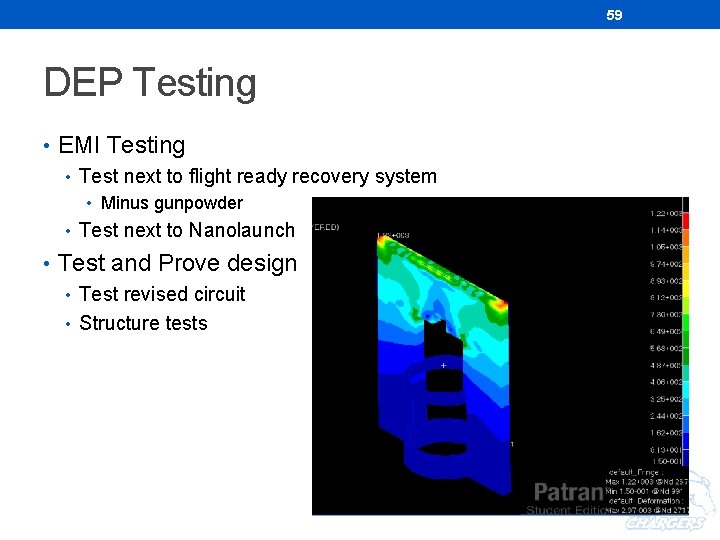
59 DEP Testing • EMI Testing • Test next to flight ready recovery system • Minus gunpowder • Test next to Nanolaunch • Test and Prove design • Test revised circuit • Structure tests
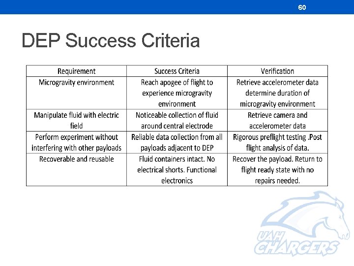
60 DEP Success Criteria
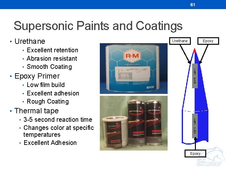
61 Supersonic Paints and Coatings • Urethane • Excellent retention • Abrasion resistant • Smooth Coating • Epoxy Primer • Low film build • Excellent adhesion • Rough Coating • Thermal tape • 3 -5 second reaction time • Changes color at specific temperatures • Excellent Adhesion Epoxy Urethane Epoxy
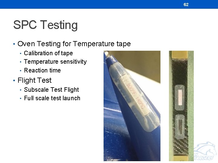
62 SPC Testing • Oven Testing for Temperature tape • Calibration of tape • Temperature sensitivity • Reaction time • Flight Test • Subscale Test Flight • Full scale test launch
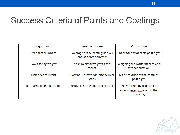
63 Success Criteria of Paints and Coatings
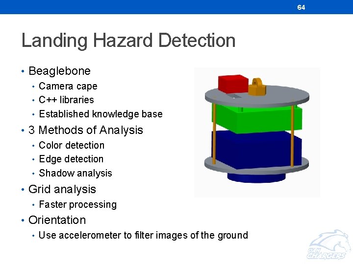
64 Landing Hazard Detection • Beaglebone • Camera cape • C++ libraries • Established knowledge base • 3 Methods of Analysis • Color detection • Edge detection • Shadow analysis • Grid analysis • Faster processing • Orientation • Use accelerometer to filter images of the ground
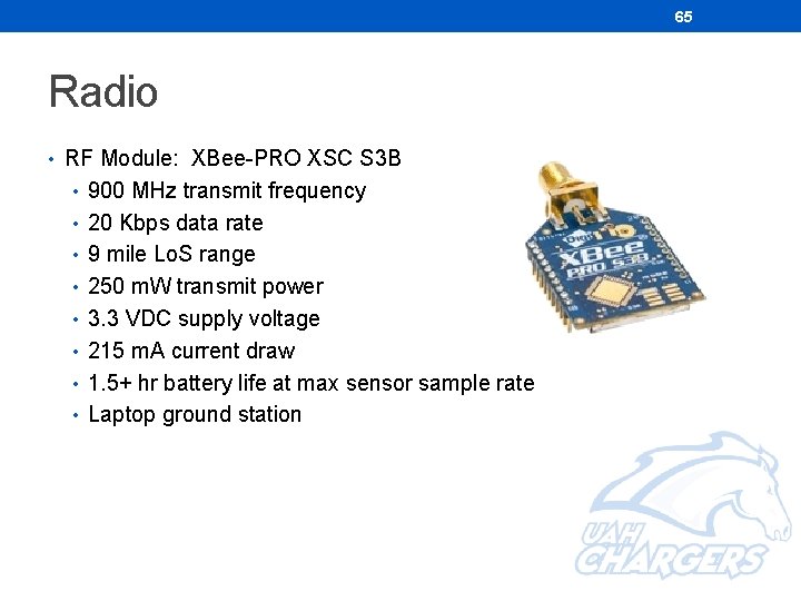
65 Radio • RF Module: XBee-PRO XSC S 3 B • 900 MHz transmit frequency • 20 Kbps data rate • 9 mile Lo. S range • 250 m. W transmit power • 3. 3 VDC supply voltage • 215 m. A current draw • 1. 5+ hr battery life at max sensor sample rate • Laptop ground station
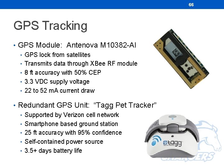
66 GPS Tracking • GPS Module: Antenova M 10382 -Al • GPS lock from satellites • Transmits data through XBee RF module • 8 ft accuracy with 50% CEP • 3. 3 VDC supply voltage • 22 to 52 m. A current draw • Redundant GPS Unit: “Tagg Pet Tracker” • Supported by Verizon cell network • Smartphone based ground station • 25 ft accuracy with 95% confidence • Self-contained power source • 3. 5+ days battery life
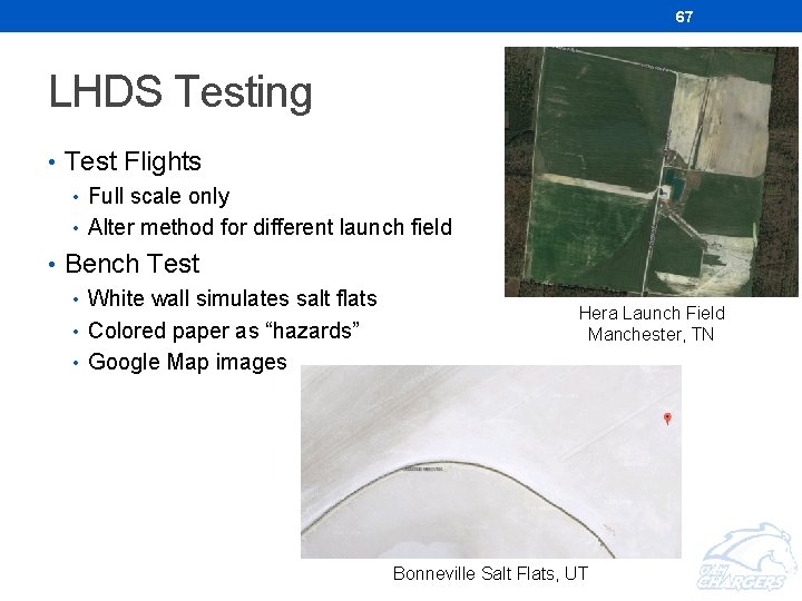
67 LHDS Testing • Test Flights • Full scale only • Alter method for different launch field • Bench Test • White wall simulates salt flats • Colored paper as “hazards” • Google Map images Hera Launch Field Manchester, TN Bonneville Salt Flats, UT
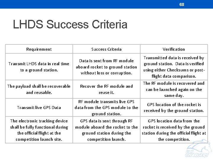
68 LHDS Success Criteria Requirement Success Criteria Verification Transmit LHDS data in real time to a ground station. Data is sent from RF module aboard rocket to ground station without loss or corruption. Transmitted data is received by ground station. Data is verified using either Checksums or postflight data comparison. The payload shall be recoverable and reusable. Recover the RF module and reuse it. The RF module is recovered and can be launched again on the same day. Transmit live GPS Data RF module transmits live GPS data from the GPS module to the ground station. GPS location of the rocket is received by the ground station. The electronic tracking device shall be fully functional during the official flight at the competition launch site. GPS data is sent through RF GPS location data from the module aboard the rocket to the rocket is received by the ground station during the official flight at competition launch. the competition.
69