
AAE 451 STRUCTURES WEIGHTS PDR 1 TEAM 4
- Slides: 21
AAE 451 STRUCTURES & WEIGHTS PDR 1 TEAM 4 Jared Hutter, Andrew Faust, Matt Bagg, Tony Bradford, Arun Padmanabhan, Gerald Lo, Kelvin Seah October 28, 2003
OVERVIEW n Materials n Wing Analysis n Tail Boom Sizing n C-G Determination n Landing Gear TEAM 4
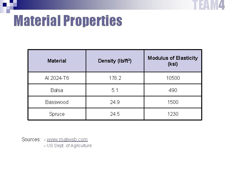
TEAM 4 Material Properties Material Density (lb/ft 3) Modulus of Elasticity (ksi) Al 2024 -T 6 178. 2 10500 Balsa 5. 1 490 Basswood 24. 9 1500 Spruce 24. 5 1230 Sources: - www. matweb. com - US Dept. of Agriculture
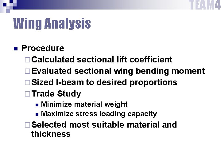
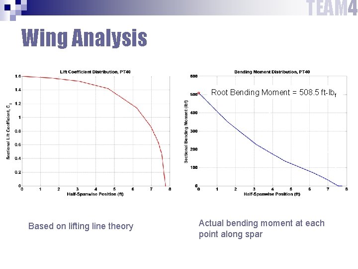
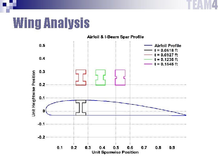
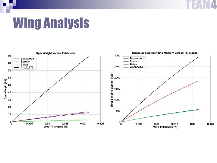
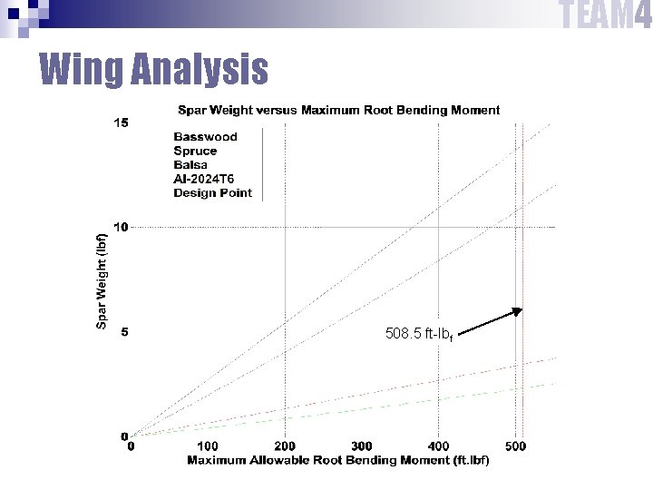
TEAM 4 Wing Analysis n Procedure ¨ Calculated sectional lift coefficient ¨ Evaluated sectional wing bending moment ¨ Sized I-beam to desired proportions ¨ Trade Study Minimize material weight n Maximize stress loading capacity n ¨ Selected most suitable material and thickness
TEAM 4 Wing Analysis Root Bending Moment = 508. 5 ft-lbf Based on lifting line theory Actual bending moment at each point along spar
TEAM 4 Wing Analysis
TEAM 4 Wing Analysis
TEAM 4 Wing Analysis 508. 5 ft-lbf
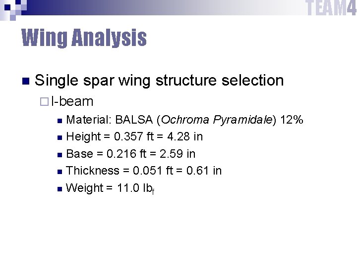
TEAM 4 Wing Analysis n Single spar wing structure selection ¨ I-beam Material: BALSA (Ochroma Pyramidale) 12% n Height = 0. 357 ft = 4. 28 in n Base = 0. 216 ft = 2. 59 in n Thickness = 0. 051 ft = 0. 61 in n Weight = 11. 0 lbf n
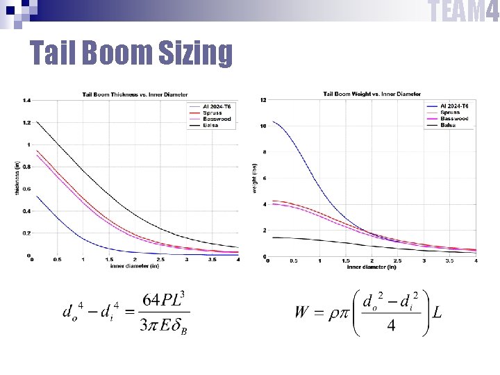
TEAM 4 Tail Boom Sizing n Cylindrical tubes ¨ Availability ¨ More efficient than solid rods Used twist and deflection constraints n Appropriately sized inner diameters n Found corresponding outer diameters n
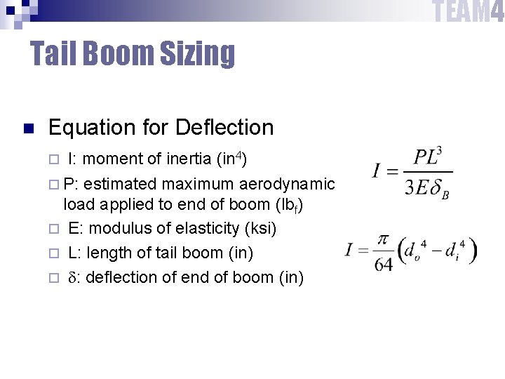
TEAM 4 Tail Boom Sizing n Equation for Deflection I: moment of inertia (in 4) ¨ P: estimated maximum aerodynamic load applied to end of boom (lbf) ¨ E: modulus of elasticity (ksi) ¨ L: length of tail boom (in) ¨ d: deflection of end of boom (in) ¨
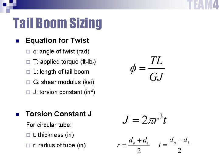
TEAM 4 Tail Boom Sizing n n Equation for Twist ¨ f: angle of twist (rad) ¨ T: applied torque (ft-lbf) ¨ L: length of tail boom ¨ G: shear modulus (ksi) ¨ J: torsion constant (in 4) Torsion Constant J For circular tube: ¨ t: thickness (in) ¨ r: radius of tube (in)
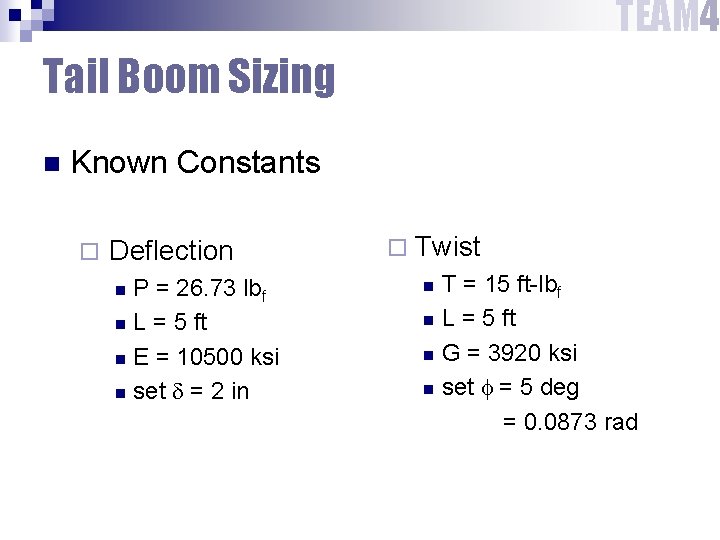
TEAM 4 Tail Boom Sizing n Known Constants ¨ Deflection P = 26. 73 lbf n L = 5 ft n E = 10500 ksi n set d = 2 in n ¨ Twist T = 15 ft-lbf n L = 5 ft n G = 3920 ksi n set f = 5 deg = 0. 0873 rad n
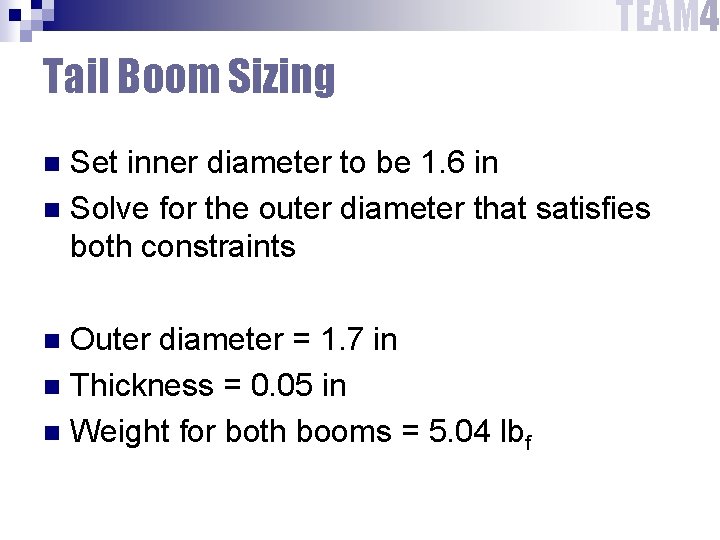
TEAM 4 Tail Boom Sizing Set inner diameter to be 1. 6 in n Solve for the outer diameter that satisfies both constraints n Outer diameter = 1. 7 in n Thickness = 0. 05 in n Weight for both booms = 5. 04 lbf n
TEAM 4 Tail Boom Sizing
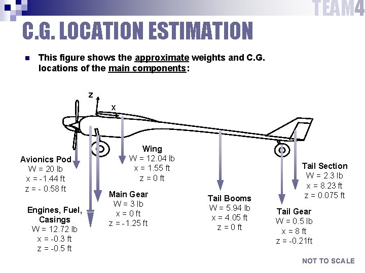
C. G. LOCATION ESTIMATION n TEAM 4 This figure shows the approximate weights and C. G. locations of the main components: z x Avionics Pod W = 20 lb x = -1. 44 ft z = - 0. 58 ft Engines, Fuel, Casings W = 12. 72 lb x = -0. 3 ft z = -0. 5 ft Wing W = 12. 04 lb x = 1. 55 ft z = 0 ft Main Gear W = 3 lb x = 0 ft z = -1. 25 ft Tail Booms W = 5. 94 lb x = 4. 05 ft z = 0 ft Tail Section W = 2. 3 lb x = 8. 23 ft z = 0. 075 ft Tail Gear W = 0. 5 lb x = 8 ft z = -0. 21 ft NOT TO SCALE
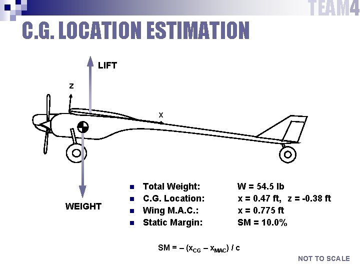
C. G. LOCATION ESTIMATION TEAM 4 LIFT z x n WEIGHT n n n Total Weight: C. G. Location: Wing M. A. C. : Static Margin: W = 54. 5 lb x = 0. 47 ft, z = -0. 38 ft x = 0. 775 ft SM = 10. 0% SM = – (x. CG – x. MAC) / c NOT TO SCALE
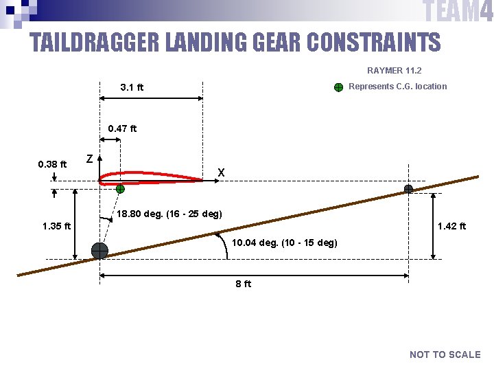
TEAM 4 TAILDRAGGER LANDING GEAR CONSTRAINTS RAYMER 11. 2 Represents C. G. location 3. 1 ft 0. 47 ft 0. 38 ft Z X 18. 80 deg. (16 - 25 deg) 1. 35 ft 1. 42 ft 10. 04 deg. (10 - 15 deg) 8 ft NOT TO SCALE
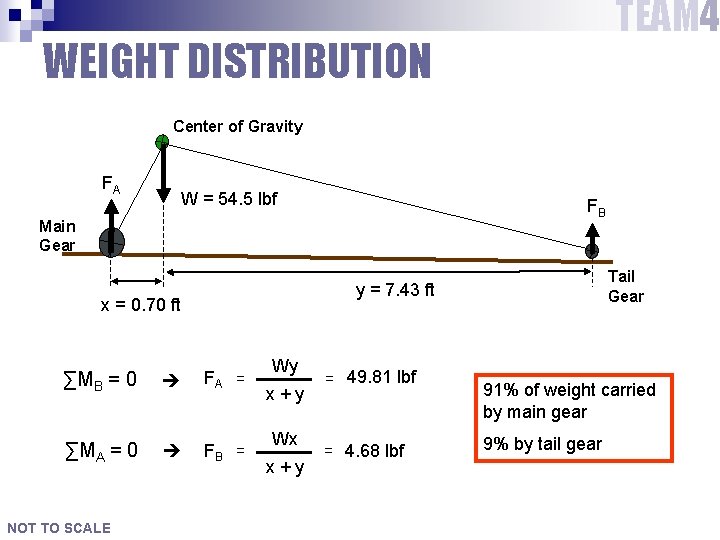
TEAM 4 WEIGHT DISTRIBUTION Center of Gravity FA W = 54. 5 lbf FB Main Gear x = 0. 70 ft ∑MB = 0 FA = ∑MA = 0 FB = NOT TO SCALE Tail Gear y = 7. 43 ft Wy x+y Wx x+y = 49. 81 lbf = 4. 68 lbf 91% of weight carried by main gear 9% by tail gear
FOLLOW-UP ACTIONS n Torsion constraint on spar n Geometry of wing ribs n Geometric layout of tail n Moments and products of inertia TEAM 4
AAE 451 QUESTIONS?