
AAE 451 Aircraft Design Aerodynamic Preliminary Design Review

- Slides: 15
AAE 451 Aircraft Design Aerodynamic Preliminary Design Review #2 Team Members Oneeb Bhutta, Matthew Basiletti , Ryan Beech, Mike Van Meter
Presentation Overview Aircraft Geometry Aerodynamic Modeling Stability and Control Derivatives Testing Status and To-Be-Finished Concerns
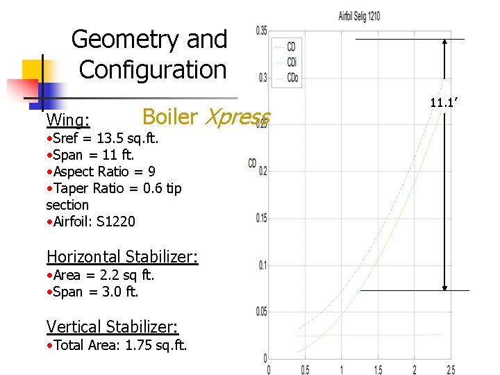
Geometry and Configuration Wing: Boiler Xpress • Sref = 13. 5 sq. ft. • Span = 11 ft. • Aspect Ratio = 9 • Taper Ratio = 0. 6 tip section • Airfoil: S 1220 Horizontal Stabilizer: • Area = 2. 2 sq ft. • Span = 3. 0 ft. Vertical Stabilizer: • Total Area: 1. 75 sq. ft. 11. 1’
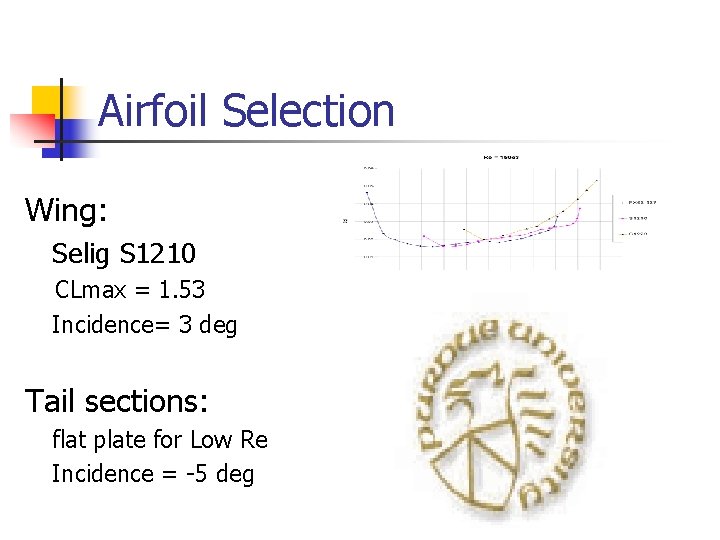
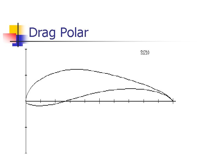
Airfoil Selection Wing: Selig S 1210 CLmax = 1. 53 Incidence= 3 deg Tail sections: flat plate for Low Re Incidence = -5 deg
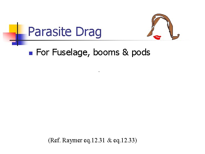
Parasite Drag n For Fuselage, booms & pods (Ref. Raymer eq. 12. 31 & eq. 12. 33)
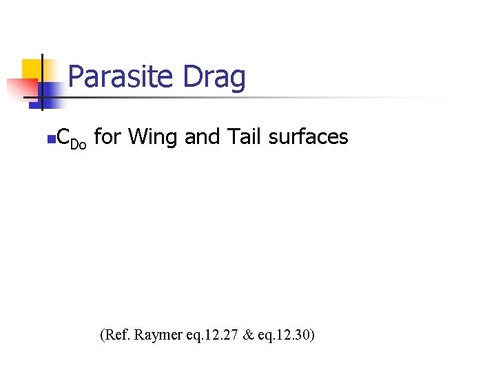
Parasite Drag C n Do for Wing and Tail surfaces (Ref. Raymer eq. 12. 27 & eq. 12. 30)
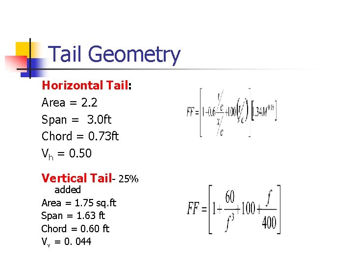
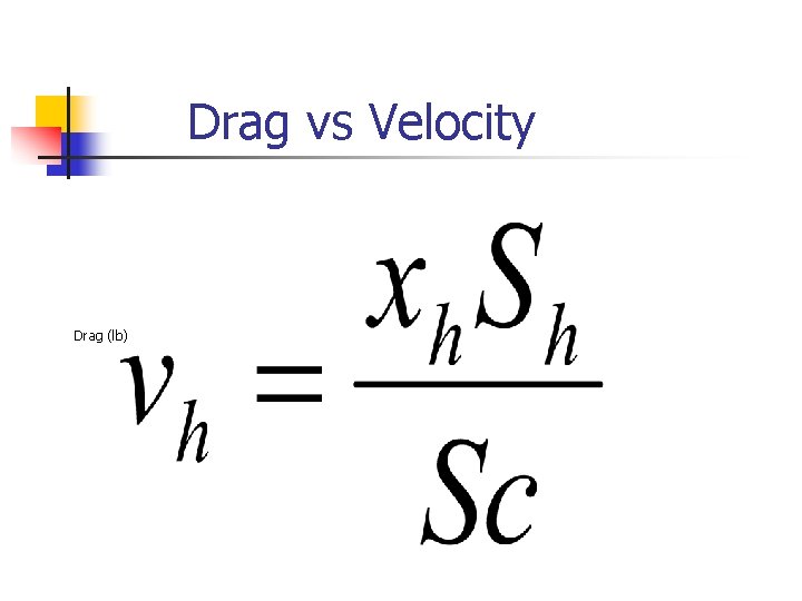
Tail Geometry Horizontal Tail: Area = 2. 2 Span = 3. 0 ft Chord = 0. 73 ft Vh = 0. 50 Vertical Tail- 25% added Area = 1. 75 sq. ft Span = 1. 63 ft Chord = 0. 60 ft Vv = 0. 044
Drag Polar
Drag vs Velocity Drag (lb)
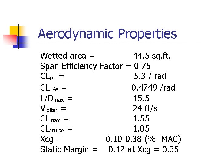
Aerodynamic Properties Wetted area = 44. 5 sq. ft. Span Efficiency Factor = 0. 75 CLa = 5. 3 / rad CL de = 0. 4749 /rad L/Dmax = 15. 5 Vloiter = 24 ft/s CLmax = 1. 55 CLcruise = 1. 05 Xcg = 0. 10 -0. 38 (% MAC) Static Margin = 0. 12 at Xcg = 0. 35
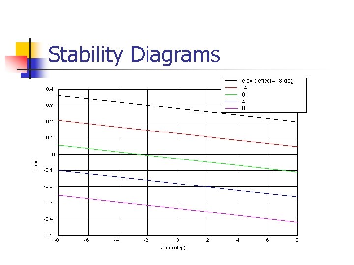
Stability Diagrams elev deflect= -8 deg -4 0 4 8 0. 4 0. 3 0. 2 0. 1 Cmcg 0 -0. 1 -0. 2 -0. 3 -0. 4 -0. 5 -8 -6 -4 -2 0 alpha (deg) 2 4 6 8
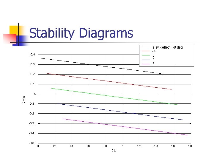
Stability Diagrams elev deflect=-8 deg -4 0 4 8 0. 4 0. 3 0. 2 0. 1 Cmcg 0 -0. 1 -0. 2 -0. 3 -0. 4 -0. 5 0 0. 2 0. 4 0. 6 0. 8 1 CL 1. 2 1. 4 1. 6 1. 8
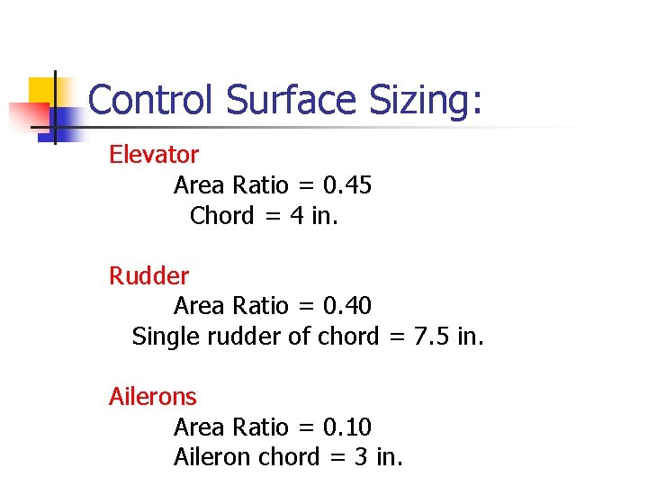
Control Surface Sizing: Elevator Area Ratio = 0. 45 Chord = 4 in. Rudder Area Ratio = 0. 40 Single rudder of chord = 7. 5 in. Ailerons Area Ratio = 0. 10 Aileron chord = 3 in.
Testing Status and TBF: Model wing nearly complete Wind tunnel test with wake survey next week CMARC model of wing to predict derivatives Calculate Dihedral angle required Use wake data to predict propeller flowfield
Concerns Will we get the CLmax we are aiming for? Are the stability derivatives for ailerons correct? Will there be a variable stability system for it to matter? Will I be around for it to matter? Can we get some covering material to stick to the foam without looking like someone’s kid brother made it? Are the drag and power requirements correct to prevent being underpowered? STAY TUNED!