Structural Biology A Collaborative Necessity Or Collaborative Computing

Structural Biology: A Collaborative Necessity Or: Collaborative Computing – does it have a future? Or: What should MX Software deliver now? • West Coast Crystallographic Meeting • Monterey: March 11 th 2007

How has MX changed in 2007? • The Internet – questions can be asked answered; information found • Much more work done much faster, so desperate need for organisation of information • Better languages, Faster Computers, Better graphics • But still need good appropriate algorithms. .

Has CCP 4 helped develop New Algorithms? • Yes… maybe, but developers are free spirits – very little “contracted” software • • CCP 4 MG Coot Acorn New density modification from KDC • CCP 4 provides distribution and support; author keeps copyright, References flagged
 • Library routines")
What helps algorithm development? • Common Data structures ( formats? ) • Library routines for data handling, crystallographic operations ( Symmetry, FFTs, etc) : Libraries must be accessible to developers and there needs to be a way to update them to add routines, and to debug. They must be well documented and curated.

Cooperation – is it possible? desirable? • Advantages • Can speed up developments if library routines are well documented and accessible : • Shared efforts for maintenance and distribution extends the code lifetime • Common style helps users • Organising crystallographic data is not easy and requirements change– maybe we can agree on and provide a better standard? • Mtz model carries vital information with it.

Cooperation – is it possible? desirable? • Disadvantages • Time consuming – consultation essential : • Needs commitment by developers of algorithms and libraries– often faster to make a quick cludgey fix than read library; new routines may need to be added to libraries • Harder to get credit, raise funds • Licensing issues!

Friendly Discussion Amongst Developers? ?

The Future - Automation ? • Chemists now use crystallography as a tool and the software is robust. • MX will often be used in the same way in future– a handy technique the user cannot be expected to understand or criticise. • Obviously, automation modules must be designed by good crystallographers ( How will the good crystallographers be trained? )

What level of knowledge to assume- Discuss? • Assessing the experiment • Some understanding of crystal lattices, symmetry, point groups & spacegroups • Something about intensity statistics (at least that they exist!) • I think it is important to know the structure factor equation • Much basic information in http: //www. ccp 4. ac. uk/docs. php • (But there are still pathological cases. . See CCP 4 BB!)

• Acquiring some crystallographic know-how. How much time will people devote to this? Extracts from York tutorials given by Johan Turkenburg (most slides taken from the web) 16 slides I thought essential follow!

Crystal: unit cell + lattice + symmetry

The unit cell in three dimensions. The unit cell is defined by three vectors a, b, and c, and three angles , , . b a c is angle between b and c; between a and b Unit cells are usually defined in terms of the lengths of the three vectors and the three angles. For example, a=94. 2Å, b=72. 6Å, c=30. 1Å, =90°, =102. 1°, =90°.

The Seven Crystal Systems The 230 space groups can be grouped into seven crystal systems Crystal System Minimum Symmetry Bravais Lattices Unit Cell Geometry 1. Triclinic None 1. Primitive (P) a b c; 2. Monoclinic One 2 fold axis 2. Primitive (P) 3. Base-Centered (C) a b c; = = 90 3. Orthorhombic Three orthogonal 2 fold axes 4. Primitive (P) 5. Base-Centered (C) 6. Body-Centered (I) 7. Face-Centered (F) a b c; = = = 90 4. Tetragonal One 4 fold axis 8. Primitive (P) 9. Body-Centered (I) a = b c; = = = 90 5. Trigonal One 3 fold axis 10. Primitive (P) a = b c; = = 90 , = 120 11. Rhombohedral (R) a = b = c; = = 90 6. Hexagonal One 6 fold axis 10. Primitive (P) a = b c; = = 90 , = 120 7. Cubic Four 3 fold axes 12. Primitive (P) 13. Body-Centered (I) 14. Face-Centered (F) a = b = c; = = = 90
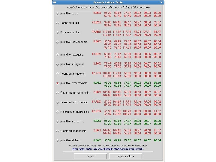

Owing to symmetry requirements some unit cells may not be primitive: In total only 14 different combinations of a, b, c and , , can exist = 14 Bravais’ lattices Therefore we can have: • P - primitive • I – body centred • A, B, C – face centred • F – all-face centred unit cells P c a C F I b B A

Symmetry Operators and Elements Apart from the identity and translational symmetry, protein crystals can only contain the following symmetry elements: Proper rotation: Rotate by 360°/n. n = 2 3 4 or 6 Screw rotation: Rotate by 360°/n & translate by d(m/n); d= unit cell edge. Proper Rotations Symbol (n) Screw Rotations Symbol (nm) Two-fold 2 21 Three-fold 3 31, 32 Four-fold 4 41, 42, 43 Six-fold 6 61, 62, 63, 64, 65

Space group diagram P 212121 Know where Int Tab A is!!

Indexing Conventions: http: //www. ccp 4. ac. uk/dist/html/reindexing. html Example: • Reindexing (CCP 4: General) - information about changing indexing regime • etc • All P 3 i and H 3: (h, k, l) not equivalent to (-h, -k, l) or (k, h, -l) or (-k, -h, -l) so we need to check all 4 possibilities: • real axes: (a, b, c) and (-a, -b, c) and (b, a, -c) and (-b, -a, c) • reciprocal axes: (a*, b*, c*) and (-a*, -b*, c*) and (b*, a*, -c*) and (-b*, -a*, c*) • i. e. reindex (h, k, l) to (-h, -k, l) or (h, k, l) to (k, h, -l) or (h, k, l) to (-k, -h, -l). • • N. B. For trigonal space groups, symmetry equivalent reflections can be conveniently described as (h, k, l), (k, i, l) and (i, h, l) where i=-(h+k). Replacing the 4 basic sets with a symmetry equivalent gives a bewildering range of possibilities!.

Many choices of Asymmetric unit and unit cell See http: //www. ccp 4. ac. uk/dist/html/alternate_origins. html Unit cell = The smallest volume from which the entire crystal can be constructed by translation only.

Diffraction Geometry

Diffraction lattice and symmetry does not mirror crystal symmetry exactly: Use Reciprocal Space definitions to describe it. . • First we need to define the relation between real space and reciprocal space. (Ie crystal lattice and diffraction space) • This requires us to look at Bragg planes and Miller indices.

Definitions used for reciprocal space • To go from real to reciprocal space we define a set of axes a*, b* and c* such that: • a* is perpendicular to b and c (b. a* = c. a* = 0) • b* is perpendicular to a and c (a. b* = c. b* = 0) • c* is perpendicular to a and b (a. c* = b. c* = 0) • a. a* = b. b* = c. c* = 1 • For orthogonal system, the length of a* is 1/(length a) • The length of a reciprocal vector d* is related to the interplanar spacing in real space as 1/d

Structure Factor Equation Very useful IF you know atom positions Very useful for understanding crystallography

Alternate representation: Structure factor can be represented by 2 -d vectors. FP Native Adding one (or more) atoms in known positions changes the structure factor in a known way Derivative FPH

Symmetry in reciprocal space • No translations • So point groups! • But: Centrosymmetry: Friedel’s law Ihkl = I-h-k-l • => 11 Laue groups

Systematic absences • Translational symmetry such as screw axes and lattice centring, leads to some reflections being ‘absent’. This can be shown using Structure Factor Formula • If a space group has a 21 screw axis along b, then this will affect the reflections 0 k 0: only k=2 n observed • If a space group has a 62 or 64 screw axis along c, then this will affect the reflections 00 l: only l=(6/2)n observed • Beware – a non-crystallographic translation of(0. 2, 0. 3, 1/3) will ALSO give these absences

Centric and Acentric reflections Centrosymmetric zones • If Ihkl = I-h-k-l for a subset of reflections under the space group symmetry without invoking Friedel’s law, then these reflections are centric. • In P 21: Ihkl = I-hk-l so for all k=0 reflections, Ih 0 l = I-h 0 -l • • Most reflections are acentric • This is relevant because: 1. Centric and Acentric intensities have different statistical properties 2. Centric phases must be or +180.

Does CCP 4 help guide Users through this? • We hope so, but the best critics are the users themselves • In general some knowledge is assumed • As far as possible programmers try to illustrate important information by presenting it graphically. • Links to documentation where possible

CCP 4 Main Page • • CCP 4 Documentation Individual Program Documentation Tutorials Maths for Protein Crystallographers Crystallographic guidance Roadmaps through the Suite Talks

Example from CCP 4 Main Page • CCP 4 Documentation • Individual program documentation • CCP 4 Tutorial • Maths for Protein Crystallographers • Eleanor Dodson prepared a document containing all the maths a protein crystallographer might need. It helps to have this all together, and available on the web, so Maria Turkenburg developed it further. It is distributed with the suite as a set of documents in which certain symbols are represented by small. gif-pictures. They are available here: • Basic Maths for Protein Crystallographers

An aside- Project Book-keeping • There is an urgent need for data management. Each specific application program needs to define its requirements and its product along with a book-keeping header e. g. Protein production needs sequence, so does automatic model building – how to pass this info on via intervening steps – from laboratory to beamline to structure solution ?

Brief Introduction to the Graphical User Interface • Designed - to keep a record of what has been done within a project directory/folder It is far from perfect but at least it exists! - to provide easy access to the tasks required for each crystallographic module - to provide diagnostic information, mostly via graphs, summaries, and as a last resort, log files CANNOT “manage” your work pattern! You must do that. .

GUI Structure Solution Modules • • • Data Processing Experimental phasing Molecular Replacement Density Improvement Model building Refinement Structure Analysis Validation and Deposition Reflection, Coordinate, Map and Graphical utilities Clipper applications Program list Needs logical up-dating! Currently underway – CCP 4 BB request for feedback soon. .

Lots of Graphical analysis from CCP 4 software
")
Scala Analysis (Scaling and Merging)

Use hklview to see diffraction zones

Intensity Distributions The structure factor equation means we can predict some properties of all INTENSITY distributions • These should be inspected as soon as data are processed • Intensity distribution v resolution • Wilson Plot • Moments • SFCHECK good too
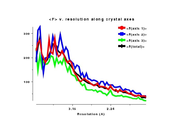

Intensity Analysis

Intensity Analysis

Lead to: Refinement problems

What level of knowledge to assume- Validation • Assessing how well the model describes the experiment and fits with expectation - COOT lists many tools • Protein geometry – Ramachandran plots Need a tool not part of refinement • Sensible contacts (Molprobity, PISA etc) • Density Fit • Unmodelled map features • Critical facilities

Solving the structure – Automation as it is now • From data through experimental phases to model • Shelx. D/Shelx. E: Decisions made within program, based on good methodology. • Solve & Resolve. Decisions made by programmer, based on expert knowledge. • Auto. Sharp: links several programs using scripting. Decisions made at scripting level? , based on expert knowledge.

More Automation Procedures • From homologous model to final model. • Molrep: Input experimental data and model – output model of asymmetric unit. (Mr Bump – Balbes) • Arp-Warp/Refmac 5. Model building using refinement & map interpretation. This uses a GUI to set a protocol, interpreted into a C-shell script. • Some CCP 4 GUI tasks

Automation Thoughts • Should procedures aim to be “black boxes”? • Yees – but I think there are too many difficult cases for this. . • Can MX be automated? Will Automation lead to rigidity? • There is a danger of this – not so serious if the approach is modular, linked by scripting. . • Will automation destroy our critical facilities
- Slides: 45