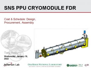
SNS PPU CRYOMODULE PDR SNS PPU Cryomodule Thermal


- Slides: 19

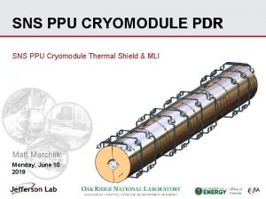
SNS PPU CRYOMODULE PDR SNS PPU Cryomodule Thermal Shield Matt Marchlik Wednesday, February 27 2019

Outline • Requirements • Design -Assembly -Component/function • Fabrication/Procurement methodology • Remaining Tasks • Summary 2

Requirements -Provide 50 K thermal radiation shielding to the cold mass -Allow for thermal contraction from 300 – 50 K -Handle the shipping design loads • (4 vertical, 5 longitudinal, 1. 5 transverse) • The shipping design loads and geometry mass has not significantly changed from the original design. The design is assumed to be adequate based on past performance 3

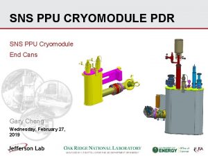
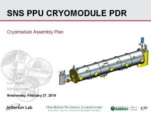
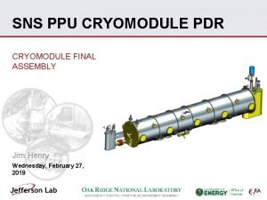
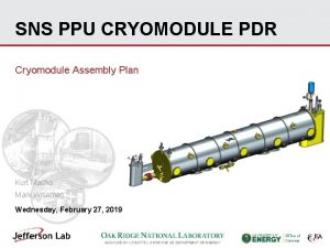
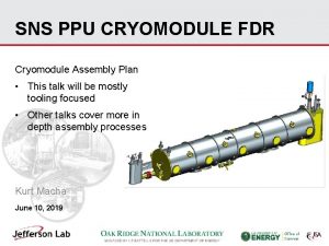
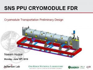
Design – Assembly Overview Supply End Shield Extension Shield segments Axial nitronic rod patch panels Tuner access Panels Helium line Shield to space frame supports Field probe cable Heat intercept blocks Return End Shield Extension All shield segments and patch panels are made from (C 11000 ETP Cu) 4

Design – Nitronic Rod Clearance Axial rod clearance slots have been widened by ~. 64” per recommendation of assembly personnel • Transverse rod clearance • Clearance for thermal contraction verified 5

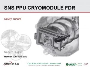
Design – Tuner Access Panel (other hidden) Panel support bracket 6

Design – Shield/Space Frame Support Shield support bands (G 11) Corner support clamps (304 SS) Shield Spacer (G 11) 7

Design – Field probe cable intercept block Updated intercept block Original intercept block • The bottom block bolts onto the shield body. No back access is needed to clamp/unclamp the cable. • The original block had three cable grooves • Field probe cable heat intercept block was reduced in size and complexity 8

Design – Nitronic Rod Intercepts • Each transverse nitronic rod is heat intercepted inside of thermal shield • Axial rods are not intercepted in the original design − It is assumed that previous calculations showed that the heat leak through the much longer rods is negligible • The original strap was made from solid copper sheet. An equivalent capacity braided copper strap was selected to replace the solid one TIG braze 9

Design – Helium Line • • • 7/8 in OD, . 045 in wall copper tubing runs along the length of the shield Tubing is segmented into 4 pieces by bellows assemblies The tubing segments are torch brazed to the shield segment’s strain relief cut outs Verified the wall thickness is acceptable per ASME B 31. 3 Verified that the SS to Cu adapter is acceptable per ASME B 16. 22 10

Design – Helium Line Brazed Shield Subassembly Bellows lock rods prevent over stretch Bellows assemblies integrated between each shield segment SS to SS weld SS to Cu socket braze 11 TIG braze Tube brazed to the strain relief fingers of the shield segments

Design – Shield Extensions • Each end of the shield is capped by an extension assembly • Allow for end can connections to be made • Supports will vary from the standard flat straps shown here. Currently being designed 12

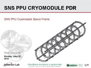
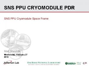
Design – Thermal Contraction • The shield assembly mounts “rigidly”(some flexibility in G 11 supports) to the spaceframe. • 300 – 50 K thermal contraction is ~. 8 in • Hardware will be omitted at two seams of the assembly to allow each segment to contract individually. Done procedurally during assembly. • Some thermal contraction relief provided by twist in the 3/16” thick G 11 bands 13

Procurement • The entire assembly, including extensions, will be procured as a complete assembly. • The SOW will be the primary fabrication control document. Drawings will direct fabricators to SOW -Fabrication plan/traveler -Materials -Welding • The shield circuit welds will be considered “code welds”. - WPS - PQR -Dimensional verification -Vendor site visits/witnessing -Shipping 14

Remaining • Design -Minor changes to shield extensions -Shield extension supports • Drawings -Finalize and review any new drawings -Start extension drawings • Procurement -SOW -PR PO 15

Summary • Preliminary thermal shield design is in good shape • Interfaces with other subsystems have been verified -Currently being considered as extensions are developed • Existing drawings have been reviewed • Extensions still under development • Majority(~90%) of drawings for design changes have been started -Extension drawings still to be created -A couple of minor patch panel drawings to be created • Procurement path understood 16

Backup − Shield cooling line code calcs 17

Backup 18

Backup 19
 Vrtic pinokio kod delte
 Rbx cal
 Thermal energy section 3
 Thermal transfer vs direct thermal printing
 Always ready rocketry
 Pdr cdr project management
 Decontrib pdr dl 50/17
 Pdr compressor
 Lilie solar
 Pdr temel kavramlar
 Pdr cdr project management
 Pdr team
 Pdr meaning security guard
 Narin acapella members
 Pdr preliminary design review
 Pdr objectives examples
 20-pdr
 Uci cinema pdr
 2016 pdr sıralama
 Pdr prisoner
