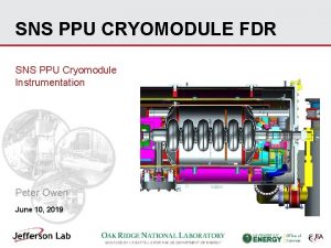
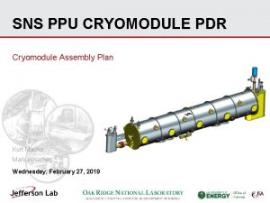
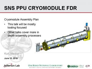
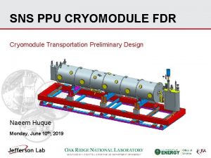
SNS PPU CRYOMODULE PDR SNS PPU Cryomodule Instrumentation


- Slides: 15

SNS PPU CRYOMODULE PDR SNS PPU Cryomodule Instrumentation Mark Wiseman February 27, 2019

Outline • Requirements • Instrumentation, locations, and instrumentation ports -CERNOX temperature sensors -Field Probe cable -Heaters -Tuners (N. Huque talk) -Instrumentation port flanges -Liquid level probes -Helium circuit pressure transducers -Vacuum vessel pressure sensors -FPC instrumentation -Miscellaneous • Two proposed changes are highlighted in talk • Remaining work 2

Overview • Requirements -PPU Interface Control Document for 2. 3 Cryomodule Integration at Jefferson Lab -SNS High Beta Cryomodule P&ID 109100501 -R 8 U-8200 -P 001 -0. 81 Beta Cryomodule Interface Control drawing CRM 9000000 -0200 • Required updates - Instrumentation interface needs a general revision - Will match what was done on the SNS HB prototype cryomodule • Reference - SNS High Beta CM instrumentation and wiring diagrams #109100501 -R 8 U-8200 -F 001, P 002, W 001 -W 006 -Original JLab SNS wiring diagrams, CRM 9008010 -1081 r. C, CRM 9004000 -0005 3

CERNOX Temperature Sensors (38 per CM) -CX-1050 -CU-HT-1. 4 L -All mounted external to helium circuits -Cavity, helium vessel & FPC (6 per, 24 total) • Helium Vessel (low and high), FPC Flange, Beam Pipe, FPC 1/3 from end (x 2) • Sensors through J 2 feedthroughs on instrumentation ports (slide 8) He Vessel High Beam Pipe He Vessel Low FPC flange FPC body (x 2) 4

CERNOX Temperature Sensors (38 per CM) -Surge Tank (2 total) • Surge tank sensors through J 23 feedthroughs on instrumentation port #1 (slide 8) -End Cans (12 total) • Supply End Can (shield inlet) x 2 • Return End Can (HX HP inlet & outlet, HX LP inlet & outlet, shield outlet) x 2 • 10 Pin CF feedthroughs on end can top plates HX LP outlet (1) 10 pin feedthrough on CF Shield supply HX HP inlet Surge tank (2) 10 pin feedthroughs on CF Shield exit HX HP outlet HX LP inlet 5

Field Probe Cable • SNS provides the field probe with the cavities • Can use original SNS design for cable -72 inches long, Drwg CRM 9007000 -1059 -SOW CRM 9007000 -1059 exists but need to remove reference to HOM cables -PROPOSE changing to right angle SMA connector at cold end • Improved stability from cool down effects -Type N connector at warm end on instrumentation port (J 6) • Alternative cable, TFLEX with Tefzel insulation, may be considered -Currently used for CEBAF and LCLS-II cryomodules -Lower cost and ends can be made up in house -Need to confirm radiation hardness • FP cable through J 6 feedthroughs on instrumentation ports (slide 8) FP Cable heat sink on thermal shield 6

Heaters • One 100 watt heater in each helium vessel -Kapton foil type heater mounted on G 10 plate • Two heaters through each 8 pin cryogenic feedthrough -Between cavities 1&2, and 3&4 • Through J 1 feedthrough on instrumentation ports (slide 8) 8 pin feedthrough for two heaters between cavities Cavity 1 Heater 7

Instrumentation Top Hat Flange Port #4 Port #3 Port #2 Port #1 One instrumentation port per cavity/helium vessel PROPOSED – mini CF flange • Port 1 only, Surge tank CERNOX diodes, 6 pin feedthrough on mini CF • Ports 2 -4 blank flange J 23 J 1 J 2 Heater, Tuner motor and limit switches (N. Huque talk) 19 Pin feedthruough Cavity/helium vessel & FPC CERNOX diodes 19 pin feedthrough J 6 Field Probe (Type N) 8

Liquid Level Probes • Two liquid level probes in helium vessel #1 • Single 8 pin cryogenic feedthrough on helium vessel exit • Single 10 pin feedthrough on top of vacuum vessel near return end flange Mini CF port for 10 pin feedthrough 8 pin feedthrough in return header Liquid Level Probes 9

Pressure Transducers • Three on end cans (supplied and installed at SNS) - High and low pressure for primary circuit - Surge tank pressure • 30/30 dial gauge and mounts for transducers (Supplied and installed by JLab) Pressure tube locations on the return end can a. b. a a) b) c) d) b c c a Sub Atmospheric Surge Tank d b Typical sub atmospheric pressure transducer manifold Isolation valve 30/30 dial gauge Low and high pressure transducer with VCR connectors Pump out port with VCR Surge tank Honeywell transducer with VCR adaptor 10 a

Vacuum Vessel Pressure Sensors • Cold Cathode Gauge (2) • Convectron Gauge (1) • Isolation and pump out valve • Mounted to NW 40 flange on vacuum vessel • All JLAB supplied Port 5 (NW 40) Pressure manifold at SNS Ref. P&ID R 8 U-8200 -P 001 r 0 11

FPC Instrumentation • All supplied by SNS • Additional instrumentation installed at SNS on air side components Thermocouple (x 2) and thermal switch Heater assembly (x 2) Electron Probe Thermocouple on exit cooling tube Window for Arc Detector 12 Cold Cathode Gauge (x 2)

Miscellaneous • JLAB to supply the primary JT, Secondary JT and cool down valve actuators • All heat shrink used will be PVDF (radiation resistant) • FPC exit flow thermocouples (4) on exit manifold • Interface panel supplied with CMs for FPC instrumentation and FPC exit thermocouples (4) CRM 90010000000 r. A Interface Panel (mounts on aisle side of CM) Thermocouples 13

Draft Drawings • Cryomodule and End Can Wiring Diagrams End Can Wiring 104212000 M 8 U 8200 -A 002 Cryomodule Assembly Wiring 104212000 M 8 U 8200 -A 001 14

Remaining • Decide on FP cable choice • Confirm wiring and all cable connections • Complete final drawings • Draft SOW’s as needed 15
