Signal Name Directio n w r t Printer


![Consider the following instructions: movi r 1, strb_L [2] out r 1, controlp [3]](https://slidetodoc.com/presentation_image_h2/77cc1d3142427549ffd7fb137cfc924e/image-14.jpg "Consider the following instructions: movi r 1, strb_L [2] out r 1, controlp [3]")
![load r 1, [r 5] out r 1, datap [5] [3] • The execution](https://slidetodoc.com/presentation_image_h2/77cc1d3142427549ffd7fb137cfc924e/image-15.jpg "load r 1, [r 5] out r 1, datap [5] [3] • The execution")
![movi strb_H [2] out r 1, controlp [3] • The execution time for these](https://slidetodoc.com/presentation_image_h2/77cc1d3142427549ffd7fb137cfc924e/image-16.jpg "movi strb_H [2] out r 1, controlp [3] • The execution time for these")
![Polling Loop again: in r 1, statusp [3] and r 1, r 3 [3]](https://slidetodoc.com/presentation_image_h2/77cc1d3142427549ffd7fb137cfc924e/image-17.jpg "Polling Loop again: in r 1, statusp [3] and r 1, r 3 [3]")


+2 =565 instructions")
 Program fragment to print 80 line character")
 Program fragment for character output")


- Slides: 36
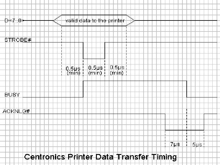
Signal Name Directio n w. r. t. Printer D<7. . 0> Input 8 -bit data bus Input STROBE# ACKNLG# BUSY PE# Pin# (25 -DB) CPU side Pin# (36 -DB) Printer side 9, 8, …, 2 1 -bit control signal High: default value. Low: read-in of data is performed. 1 1 Output 1 -bit status signal Low: data has been received and the printer is ready to accept new data. High: default value. 10 10 Output 1 -bit status signal Low: default value High: see note#1 11 11 Output 1 -bit status signal High: the printer is out of paper. Low: default value. 12 12 1 -bit control signal Low: the printer controller is reset to its initial state and the print buffer is cleared. High: default value. 16 31 1 -bit status signal High: the printer is in selected state. 13 13 14 14 17 36 15 32 INIT# Input SLCT Output AUTO FEED XT# Input SLCT IN# ERROR# Input Output Function Summary 1 -bit control signal Low: paper is automatically fed after one line. 1 -bit control signal Low: data entry to the printer is possible. High: data entry to printer is not possible. 1 -bit status signal Low: see note#2. High: default value.
CS 501 Advanced Computer Architecture Lecture 26 Dr. Noor Muhammad Sheikh
Centronics Bit Assignment for the I/O Ports Logical Address Description 7 6 5 4 3 2 1 0 D<3> D<2> D<1> D<0> Unused 0 8 -bit output port for DATA D<7> D<6> D<5> D<4> 1 8 -bit input port for STATUS BUSY ACKNLG# PE# SLCT ERROR# Unused 2 8 -bit output port for CONTROL Unused IRQEN SLCT IN# INIT# Auto Feed XT# DIR STROBE#
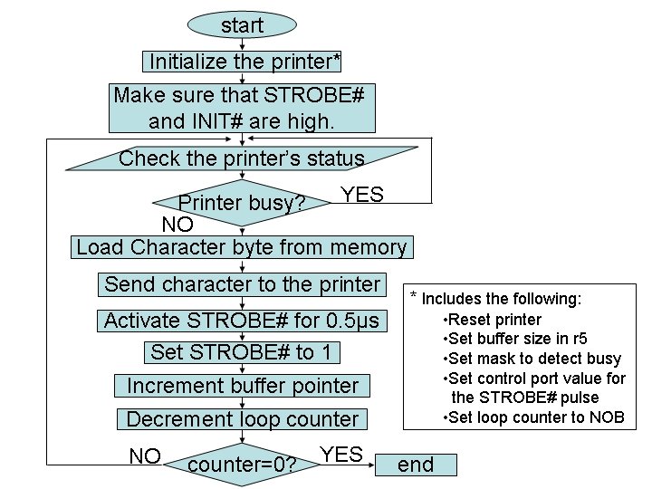
Problem Statement Assuming that a Centronics parallel printer is interfaced to the FALCON-A processor, as shown in example 9 -4, write an assembly language program to send an 80 character line to the printer. Assume that the line of characters is stored in the memory starting at address 1024.
movi r 1, reset out r 1, controlp ; use r 1 for ; data transfer
Polling loop again: in r 1, statusp ; and r 1, r 3 ; test if BUSY = 1 jnz r 1, [again] ; wait if BUSY = 1 ;
; filename: Example_11 -8. asmfa ; ; This program sends an 80 character line ; to a FALCON-A parallel printer ; ; Notes: ; 1. 8 -bit printer data bus connected to ; D<7. . 0> of the FALCON-A (remember big-endian) ; Thus, the printer actually uses addresses 57, 59 & 61 ; ; 2. one character per 16 -bits of data xfered ; ; . org 400 ; NOB: . equ 80 ; movi r 5, 32 mul r 5, r 5 ; r 5 holds 1024 temporarily ; movi r 3, 1 shiftl r 3, 7 ; to set mask to 0080 h
datap: . equ 56 statusp: . equ 58 controlp: . equ 60 ; reset: . equ 1 ; used to set unidirectional, no interrupts, ; auto line feed, and strobe high ; strb_H: . equ 5 strb_L: . equ 4 ; movi r 1, reset ; use r 1 for data xfer out r 1, controlp ; movi r 7, NOB ; use r 7 as character counter ;
again: in r 1, statusp ; and r 1, r 3 ; test if BUSY = 1 ? jnz r 1, [again] ; wait if BUSY = 1 ; load r 1, [r 5] out r 1, datap movi r 1, strb_L out r 1, controlp movi r 1, strb_H out r 1, controlp addi r 5, 2 subi r 7, 1 jnz r 7, [again] halt
movi r 7, NOB ; again: in r 1, statusp and r 1 , r 1, r 3 jnz r 1, [again] [2] [3] [4] ; load r 1, [r 5] out r 1, datap movi r 1, strob_L out r 1, controlp movi r 1, s trob_H out r 1, controlp addi r 5, 2 subi r 7, 1 jnz r 7, [again] halt [5] [3] [2] [3] [3] [4]
Consider the following instructions: movi r 1, strb_L [2] out r 1, controlp [3] • The execution time for these two instructions is 2+3 = 5 clock periods.
load r 1, [r 5] out r 1, datap [5] [3] • The execution time for these two instructions is 5+3 = 8 clock periods.
movi strb_H [2] out r 1, controlp [3] • The execution time for these two instructions is 2+3 = 5 clock periods.
Polling Loop again: in r 1, statusp [3] and r 1, r 3 [3] jnz r 1, [again] [4] • The execution time required by the polling loop is 3+3+4 = 10 clock periods.
Time required by polling loop The polling loop takes 10 clock cycles. For a 10 MHz FALCON-A CPU, this is 10 x 100=1 s One pass of the main loop =3+3+4+5+3+2+3+3+3+4 =38 clock cycles Hence 38 x 100=3. 8 s
Efficiency of polling Assuming a 1000 character per second printer connected to FALCON-A CPU, 1 character is printed every 1000 s. Hence the CPU will wait for 1000 -3. 8 996 s before sending the next character. Thus the poling loop will be executed about 996 times for every character which is very inefficient.
Buffer • A small memory inside the printer • CPU interacts with printer through buffer • Buffer relieves the CPU to perform other tasks while the printer is busy
Example • Assume a 64 byte FIFO buffer inside a 1000 cps printer • Time required to print a character is 1 ms.
Modified program code again: in r 1, statusp and r 1 , r 1, r 3 jnz r 1, [again] [3] [4] load r 1, [r 5] out r 1, datap addi r 5, 2 subi r 7, 1 jnz r 7, [again] [5] [3] [3] [4] ;
Program execution time Polling loop still takes 10 clock periods or 1 s. The main loop of the program is executed in 3+3+4+5+3+3+3+4=28 clock cycles. For a 10 MHz FALCON-A CPU, 28 x 100=2. 8 s
Efficiency of polling The outer loop will execute 64 times before the BUSY signal goes to 1. After that the polling loop will execute for about 996 times before BUSY goes to 0.
Using a larger buffer • Cost of printer will increase • Same situation arises after the buffer is filled up
Output register COUT = FFFFF 114 H Status register COSTAT = FFFFF 110 H
lar ldr Wait: ld brpl st r 3, Wait r 2, Char r 1, COSTAT r 3, r 1 r 2, COUT ; Set branch target for wait. ; Get character for output. ; Read device status register, ; Branch to Wait if not ready. ; Output character and start device.
Output Register LOUT = FFFFF 134 H Status Register LSTAT = FFFFF 130 H Unused Print Line Command Register LCMD = FFFFF 138 H
lar la lar Wait: ld brpl ld st addi brnz la st r 1, Buff r 2, 80 r 3, Wait r 0, LSTAT r 3, r 0, 0(r 1) r 0, LOUT r 1, 4 r 2, -1 r 3, r 2 r 0, 1 r 0, LCMD ; Set pointer to character buffer. ; Initialize character counter and ; branch target. ; Ready bit, ; test, and repeat if not ready. ; Get next character from buffer, ; and send to printer. ; Advance character pointer, and ; count character. ; If not last, go wait on ready. ; Get a print line command, ; and send it to the printer.
• Buff = Pointer to character Buffer. • Two nested loops starting at the label Wait: 1). The two instruction inner loop, which waits for Ready. 2). The outer seven-instruction loop.
The outer seven-instruction loop perform following tasks: • Outputs a character • Advance the buffer pointer • Decrement the register containing the number of characters left to print • Repeat if there are more characters left to send. The last two instructions issue the command to print the line.
Instruction count Total instruction count to print a line =3+(80 x 7)+2 =565 instructions
Figure 8. 9 (jordan) Program fragment to print 80 line character
Figure 8. 8 (jordan) Program fragment for character output
Review
Start: la la Check: ld brmi ld ld brpl ld ld st addi brnz la st Next: addi brnz brzr r 2, 0 r 3, 1 r 0, Done(r 2) r 4, r 0 r 3, 0 r 0, CICTL(r 2) r 4, r 0, CIN(r 2) r 1, Bufp(r 2) r 0, 0(r 1) r 1, 4 r 1, Bufp(r 2) r 0, -CR r 4, r 0, -1 r 0, Done(r 2) r 2, 8 r 0, r 2, -256 r 5, r 0 r 6, r 3 ; Point to first device, and ; set all inactive flag. ; See if device still active, and ; if not, go advance to next device. ; Clear the all inactive flag. ; Get device ready flag, and ; go advance to next if not ready. ; Get character and ; correct buffer pointer, and ; store character in buffer. ; Advance character pointer, ; and return it to memory. ; Check for carriage return, and ; if not, go advance to next device. ; Set done flag to -1 on ; detecting carriage return. ; Advance device pointer, and ; if not last device, ; go check next one. ; If a device is active, make a new pass.