SERIES RESONANT CIRCUIT Circuit configuration Resistor Inductor and

")
= -------2∏ √")
 = f 2 – f 1 =")


 = Ao + A 1 sin wt")


- Slides: 41
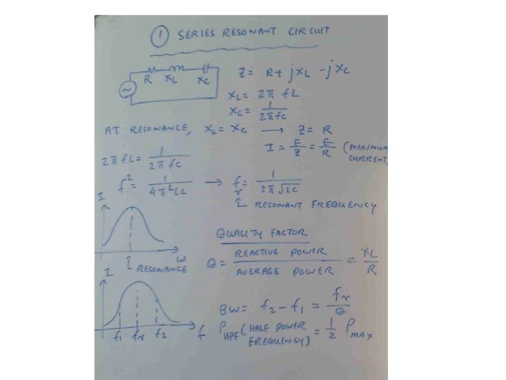
SERIES RESONANT CIRCUIT • Circuit configuration– Resistor, Inductor and capacitor are connected in series • Z= R + J Xl –J Xc • Resonance occur when X l = Xc • Xl = 2 ∏ f L Xl= Inductive Reactance (Ω) • f = frequency (HZ) • L= Inductance ( Henry)
SERIES RESONANT CIRCUIT 1 • Xc =------2∏f. C Where Xc = Capacitive reactance (Ω) f = Frequency (HZ) C= Capacitance (Farad)
Resonant Frequency & Quality Factor • • • 1 Resonant frequency (Fr)= -------2∏ √ L C Reactive Power Xl Quality Factor (Q) = ------------ = ------Active Power R
Band Width • fr • Bandwidth (BW) = f 2 – f 1 = ------Q F 1 - Lower cut off frequency, F 2= Upper cut off frequency Phf = Half power frequency = ½ P max
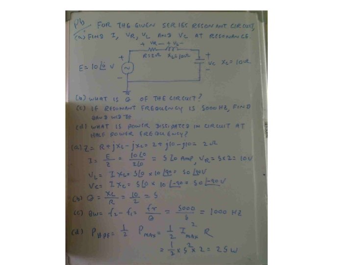
RLC Series Connection • RLC Series connection • Z = R + j Xl – j Xc E • I = ------Z
Calculation of series RLC circuit • Vl= I x. Xl • Vc = I x Xc fr • BW= f 2 – f 1 = -------Q • Phpf = ½ P max = ½ I max 2 R
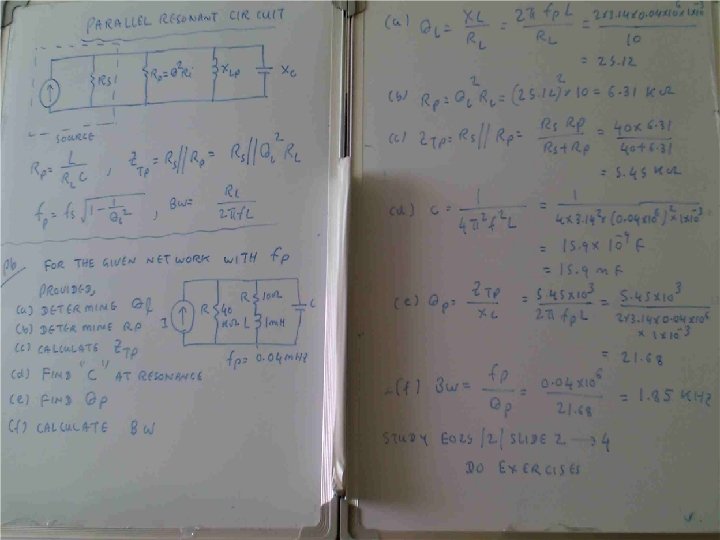
Parallel Resonant Circuit L • Rp = -----Rl x C • Ztp =Rs parallel with Rp= Rs parallel with Ql 2 Rl • Fp = fs 1 1 - -------Ql 2 Rl , Bw = -------2 ∏f. L
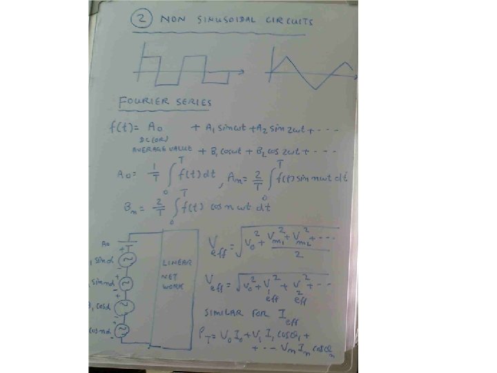
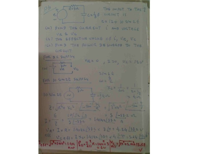
Non sinusoidal circuits & Fourier Series F(t) = Ao + A 1 sin wt + A 2 sin 2 wt + ------+ B 1 cos wt + B 2 cos 2 wt+ ----
Calculation of effective voltage Vm 1 2 + Vm 2 2 + -------- • V eff = Vo 2 + ---------------------2 • Veff = Vo 2 + V 1 eff 2 + V 2 eff 2 + ----------
Total power • P t = V o I o + V 1 I 1 cos Ѳ 1 + V 2 I 2 cos Ѳ 1+ ------------- + Vn In cos Ѳ n
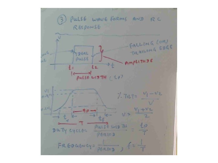
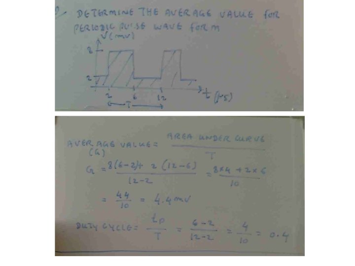
PULSE WAVEFORM & RC RESPONSE V 1 - V 2 • % Tilt = ---------V V 1 + V 2 • V = ---------2
DUTY CYCLE Pulse width tp • Duty cycle = ------------ = -------Period T 1 1 • Frequency = --------- , f = ------Period T