
PA 114 Core GRe P Resonance in LCR
- Slides: 12
PA 114 Core GRe. P Resonance in LCR circuits
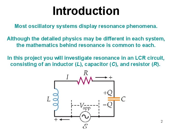
Introduction Most oscillatory systems display resonance phenomena. Although the detailed physics may be different in each system, the mathematics behind resonance is common to each. In this project you will investigate resonance in an LCR circuit, consisting of an inductor (L), capacitor (C), and resistor (R). 2
Approach: Build and understand the operation of an LCR circuit Find how the behaviour of LCR circuits, and especially the resonant frequency, depend on the values of L, C, and R. Determine how the resonant frequency can be used to measure C. Use this knowledge to measure the dielectric constant of an unknown substance (sugar). Equipment provided: Signal generator and oscilloscope (on the computer) Coils (Inductors); fixed and variable capacitors; resistors Parallel plate capacitor and sugar 3
Relation to Core Courses PA 1140 SHM Resonance PA 1720 LCR circuits Dissipation PA 1130 Inductance Capacitance, dielectric constant 4
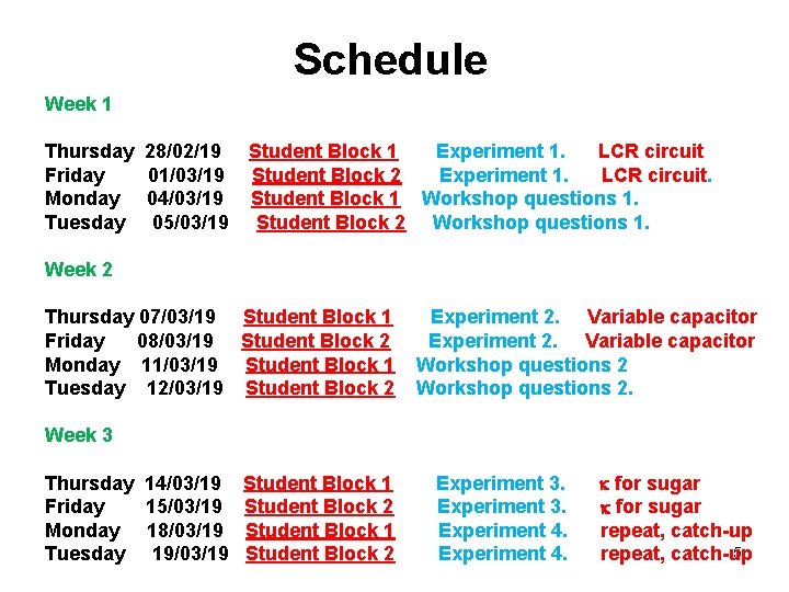
Schedule Week 1 Thursday 28/02/19 Student Block 1 Experiment 1. LCR circuit Friday 01/03/19 Student Block 2 Experiment 1. LCR circuit. Monday 04/03/19 Student Block 1 Workshop questions 1. Tuesday 05/03/19 Student Block 2 Workshop questions 1. Week 2 Thursday 07/03/19 Student Block 1 Experiment 2. Variable capacitor Friday 08/03/19 Student Block 2 Experiment 2. Variable capacitor Monday 11/03/19 Student Block 1 Workshop questions 2 Tuesday 12/03/19 Student Block 2 Workshop questions 2. Week 3 Thursday 14/03/19 Student Block 1 Experiment 3. k for sugar Friday 15/03/19 Student Block 2 Experiment 3. k for sugar Monday 18/03/19 Student Block 1 Experiment 4. repeat, catch-up 5 Tuesday 19/03/19 Student Block 2 Experiment 4. repeat, catch-up
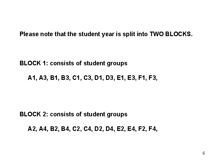
Please note that the student year is split into TWO BLOCKS. BLOCK 1: consists of student groups A 1, A 3, B 1, B 3, C 1, C 3, D 1, D 3, E 1, E 3, F 1, F 3, BLOCK 2: consists of student groups A 2, A 4, B 2, B 4, C 2, C 4, D 2, D 4, E 2, E 4, F 2, F 4, 6
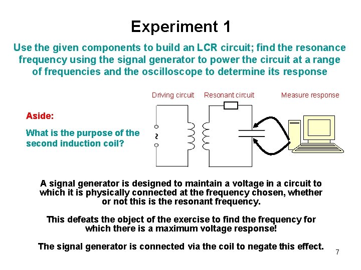
Experiment 1 Use the given components to build an LCR circuit; find the resonance frequency using the signal generator to power the circuit at a range of frequencies and the oscilloscope to determine its response Driving circuit Resonant circuit Measure response Aside: What is the purpose of the second induction coil? A signal generator is designed to maintain a voltage in a circuit to which it is physically connected at the frequency chosen, whether or not this is the resonant frequency. This defeats the object of the exercise to find the frequency for which there is a maximum voltage response! The signal generator is connected via the coil to negate this effect. 7
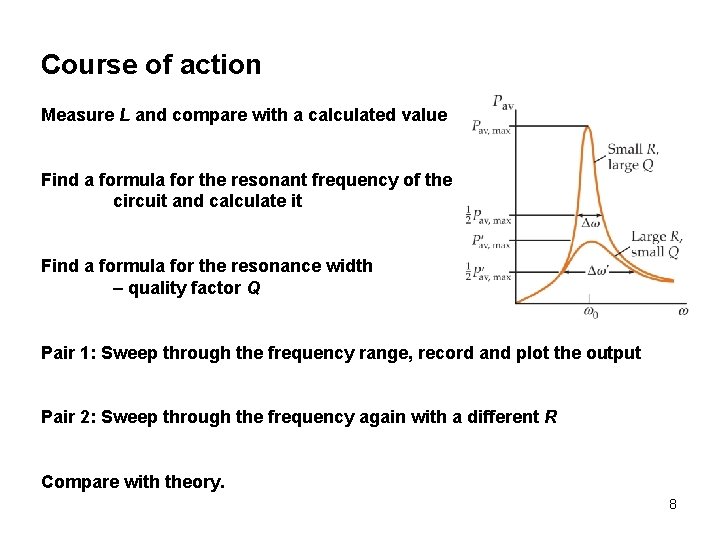
Course of action Measure L and compare with a calculated value Find a formula for the resonant frequency of the circuit and calculate it Find a formula for the resonance width – quality factor Q Pair 1: Sweep through the frequency range, record and plot the output Pair 2: Sweep through the frequency again with a different R Compare with theory. 8
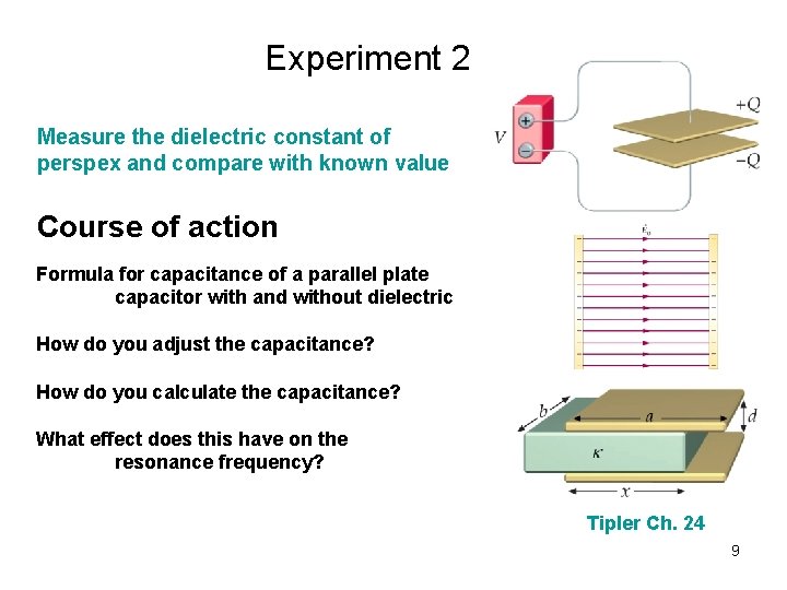
Experiment 2 Measure the dielectric constant of perspex and compare with known value Course of action Formula for capacitance of a parallel plate capacitor with and without dielectric How do you adjust the capacitance? How do you calculate the capacitance? What effect does this have on the resonance frequency? Tipler Ch. 24 9
Experiment 3 Measure the dielectric constant of sugar Course of action Use the knowledge gained in previous experiments to determine the dielectric constant of an “unknown” substance Experiment 4 Repeat measurements, catch up, finish off. 10
Core GRe. P rules – a reminder The problems should be worked through in order. Keep a project plan and copious notes in your laboratory notebooks. Each member of the group must engage with all aspects of each problem. This should be apparent from your notebooks. It is more important to complete the tasks effectively and reflectively than to rush to the end. You will be assessed on your engagement with the problem. You must attend laboratory sessions but you may work outside scheduled classes if you wish. If you do not have time to obtain data for all the experiments your report should indicate how you would have collected data and how you would have analysed it. The report is a group responsibility; it should be clear that it has been “signed off” by the group as a whole. 11
Submission of reports Files are submitted to Blackboard under the module PA 1900: Experiment Physics 1 2018 -10 Y > Assessment and Feedback > PA 1900 GRe. P Report 2018 -19 Instructions are in your documentation. Files MUST be named with the following convention 114 GRe. P_Group Letter_User. Name_Report. filetype e. g. 114 GRe. P_Group A 1_zyx 5_Report. pdf and KEEP A COPY Submission Deadline for Group Reports: 2 pm Thursday 28 March 12