
Design of Ideal Intake Systems for I C

- Slides: 21
Design of Ideal Intake Systems for I. C. Engine P M V Subbarao Professor Mechanical Engineering Department Design Features for effective breathing….
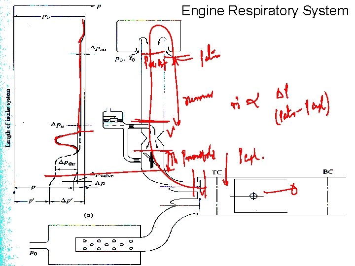
Engine Respiratory System
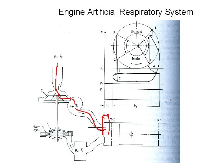
Engine Artificial Respiratory System
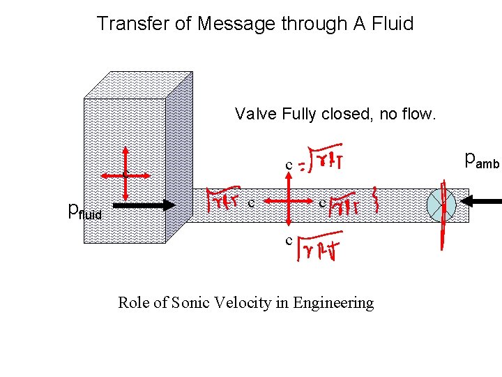
Transfer of Message through A Fluid Valve Fully closed, no flow. c pfluid pamb c c Role of Sonic Velocity in Engineering
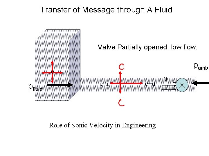
Transfer of Message through A Fluid Valve Partially opened, low flow. pamb c pfluid c-u c+u Role of Sonic Velocity in Engineering u
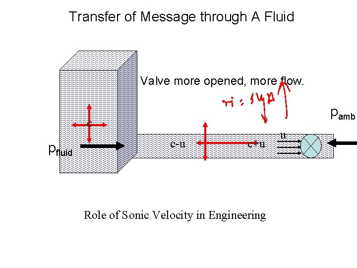
Transfer of Message through A Fluid Valve more opened, more flow. pamb c pfluid c-u c+u Role of Sonic Velocity in Engineering u
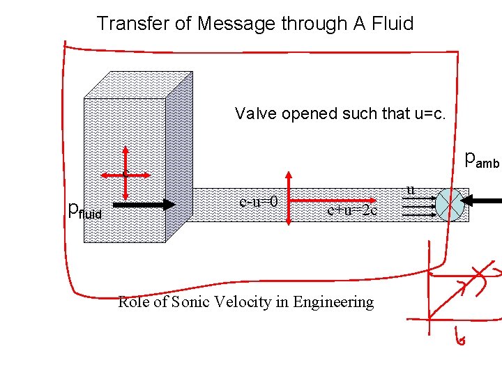
Transfer of Message through A Fluid Valve opened such that u=c. pamb c pfluid c-u=0 u c+u=2 c Role of Sonic Velocity in Engineering
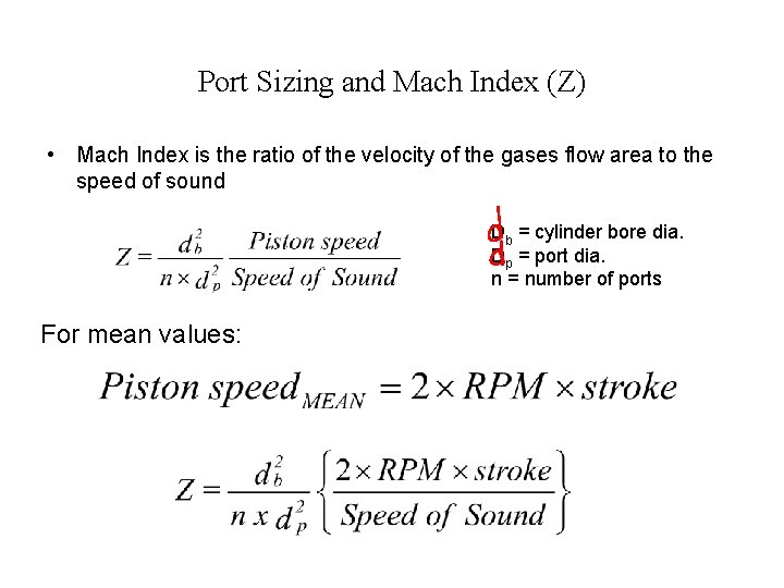
Port Sizing and Mach Index (Z) • Mach Index is the ratio of the velocity of the gases flow area to the speed of sound Db = cylinder bore dia. Dp = port dia. n = number of ports For mean values:
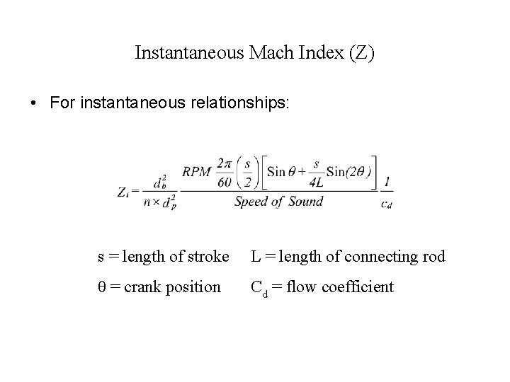
Instantaneous Mach Index (Z) • For instantaneous relationships: s = length of stroke L = length of connecting rod θ = crank position Cd = flow coefficient
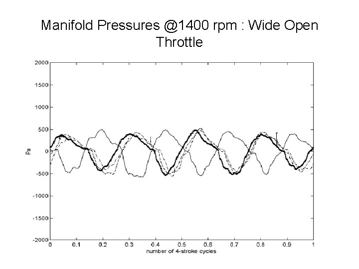
Manifold Pressures @1400 rpm : Wide Open Throttle
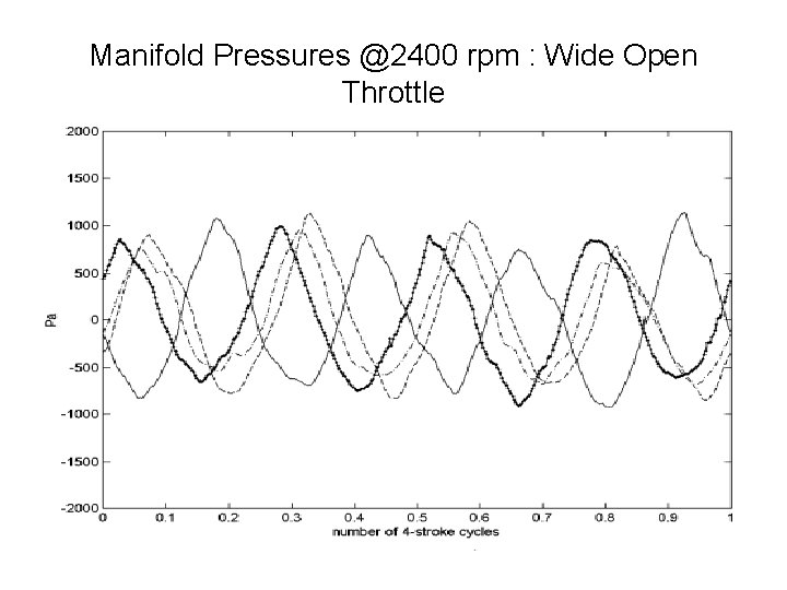
Manifold Pressures @2400 rpm : Wide Open Throttle
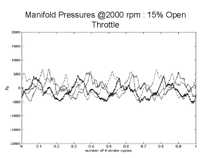
Manifold Pressures @2000 rpm : 15% Open Throttle
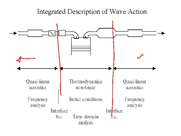
Integrated Description of Wave Action
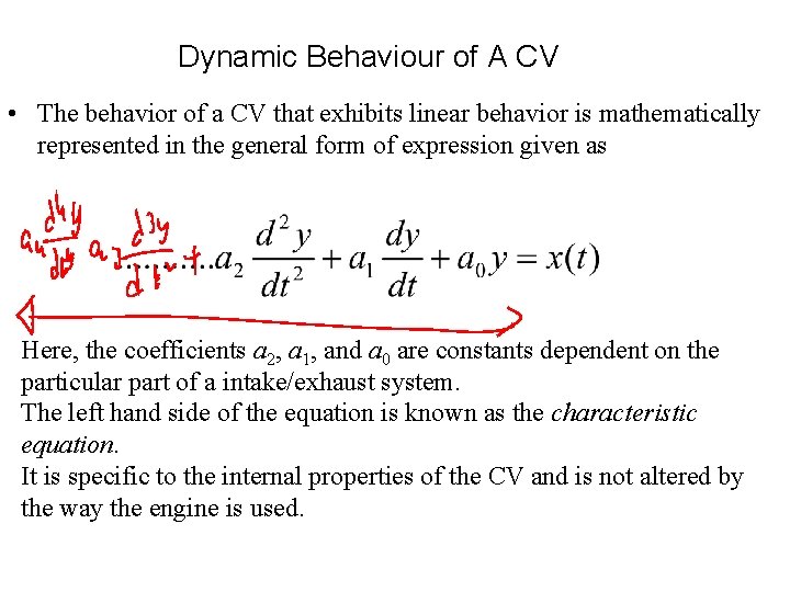
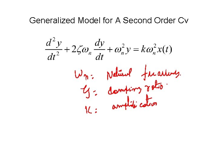
Dynamic Behaviour of A CV • The behavior of a CV that exhibits linear behavior is mathematically represented in the general form of expression given as Here, the coefficients a 2, a 1, and a 0 are constants dependent on the particular part of a intake/exhaust system. The left hand side of the equation is known as the characteristic equation. It is specific to the internal properties of the CV and is not altered by the way the engine is used.
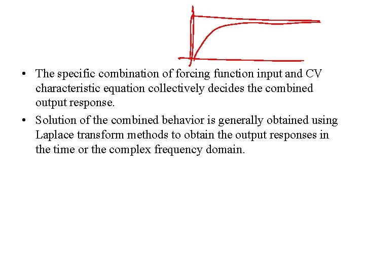
• The specific combination of forcing function input and CV characteristic equation collectively decides the combined output response. • Solution of the combined behavior is generally obtained using Laplace transform methods to obtain the output responses in the time or the complex frequency domain.
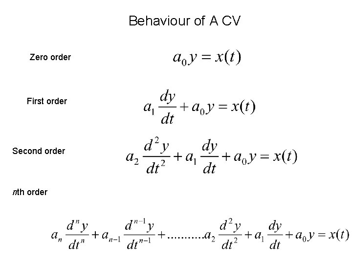
Behaviour of A CV Zero order First order Second order nth order
Behaviour of A CV • Note that specific names have been given to each order. • The zero-order situation is not usually dealt because it has no time-dependent term and is thus seen to be trivial. • It is an amplifier (or attenuator) of the forcing function with gain of a 0. • It has infinite bandwidth without change in the amplification constant. • The highest order usually necessary to consider in first-cut CV analysis is the second-order class. • Higher-order systems do occur in. • Computer-aided tools for systems analysis are used to study the responses of higher order systems.
Generalized Model for A Second Order Cv
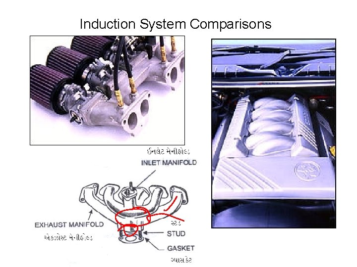
Induction System Comparisons
Acoustic Theory of Piping • The intake manifold to an internal combustion (IC) engine will consist of a network of interconnecting pipes. • The lengths of these pipes, and to a certain extent their diameters, must be chosen carefully as they will determine the resonant frequencies of the manifold. • When the engine is run at a speed where one or more of these resonances is excited, then both the volumetric efficiency and the intake noise level maybe affected.
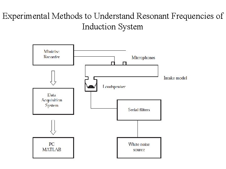
Experimental Methods to Understand Resonant Frequencies of Induction System