Selective Coordination Productivity Through Protection Seminar Series Agenda



- Slides: 30
Selective Coordination Productivity Through Protection Seminar Series
Agenda Selective Coordination Ø Ø Ø Ø What is selective coordination Mandatory Requirements Why mandatory How to comply with fuses Benefits of fusible system Cooper Bussmann solutions Resources 3
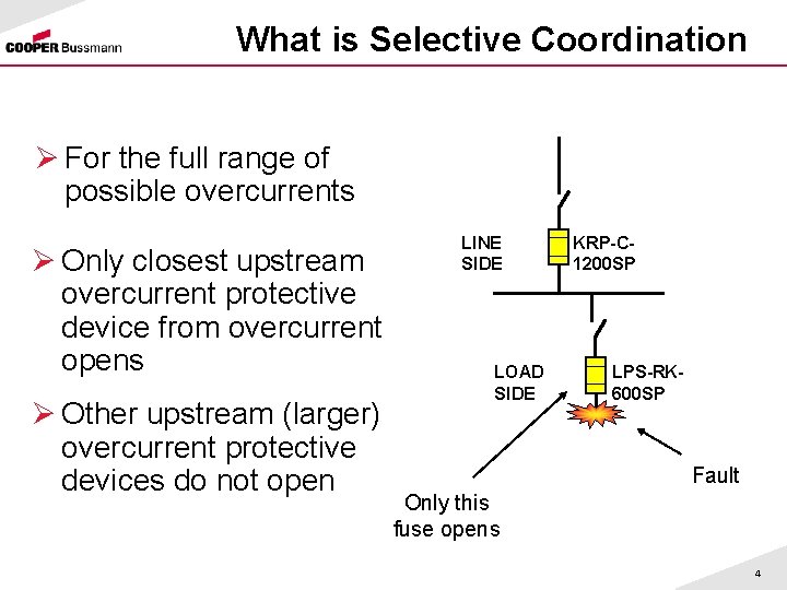
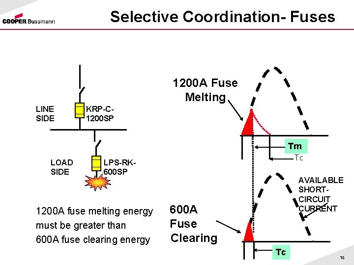
What is Selective Coordination Ø For the full range of possible overcurrents Ø Only closest upstream overcurrent protective device from overcurrent opens Ø Other upstream (larger) overcurrent protective devices do not open LINE SIDE LOAD SIDE KRP-C 1200 SP LPS-RK 600 SP Fault Only this fuse opens 4
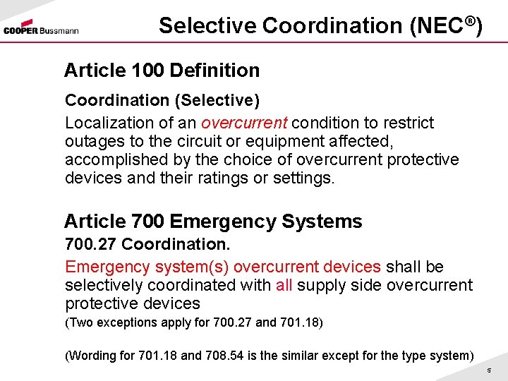
Selective Coordination (NEC®) Article 100 Definition Coordination (Selective) Localization of an overcurrent condition to restrict outages to the circuit or equipment affected, accomplished by the choice of overcurrent protective devices and their ratings or settings. Article 700 Emergency Systems 700. 27 Coordination. Emergency system(s) overcurrent devices shall be selectively coordinated with all supply side overcurrent protective devices (Two exceptions apply for 700. 27 and 701. 18) (Wording for 701. 18 and 708. 54 is the similar except for the type system) 5
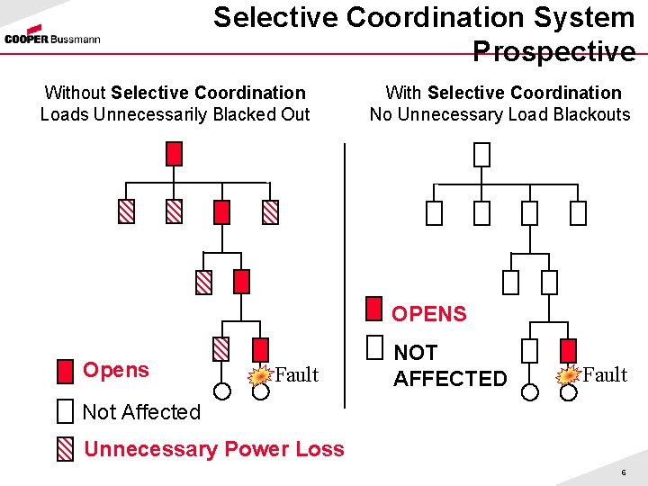
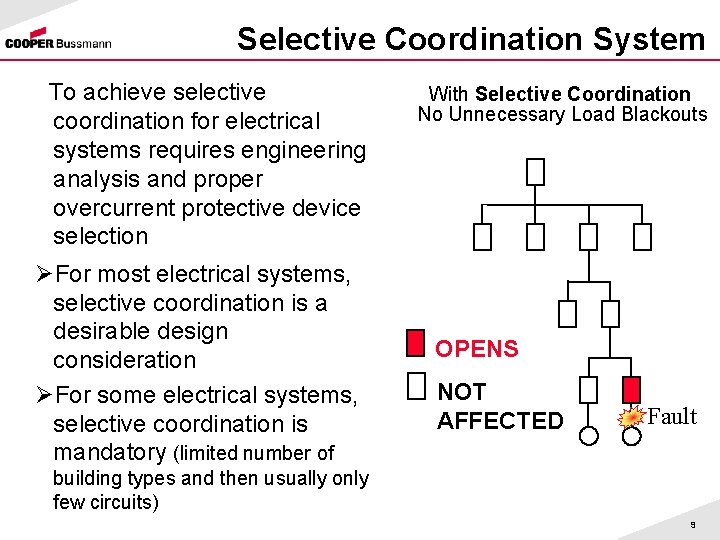
Selective Coordination System Prospective Without Selective Coordination Loads Unnecessarily Blacked Out With Selective Coordination No Unnecessary Load Blackouts OPENS Opens Fault NOT AFFECTED Fault Not Affected Unnecessary Power Loss 6
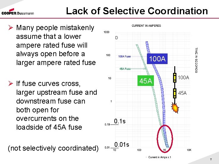
Lack of Selective Coordination Ø Many people mistakenly assume that a lower ampere rated fuse will always open before a larger ampere rated fuse Ø If fuse curves cross, larger upstream fuse and downstream fuse can both open for overcurrents on the loadside of 45 A fuse (not selectively coordinated) D 100 A 45 A 0. 1 s 0. 01 s 7
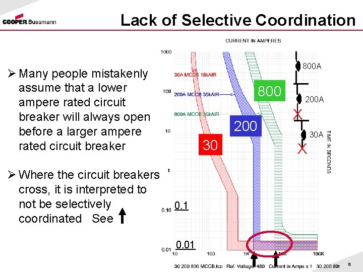
Lack of Selective Coordination 800 A Ø Many people mistakenly assume that a lower ampere rated circuit breaker will always open before a larger ampere rated circuit breaker Ø Where the circuit breakers cross, it is interpreted to not be selectively coordinated See 800 200 30 200 A X 30 A X 0. 1 0. 01 8
Selective Coordination System To achieve selective coordination for electrical systems requires engineering analysis and proper overcurrent protective device selection ØFor most electrical systems, selective coordination is a desirable design consideration ØFor some electrical systems, selective coordination is mandatory (limited number of With Selective Coordination No Unnecessary Load Blackouts OPENS NOT AFFECTED Fault building types and then usually only few circuits) 9
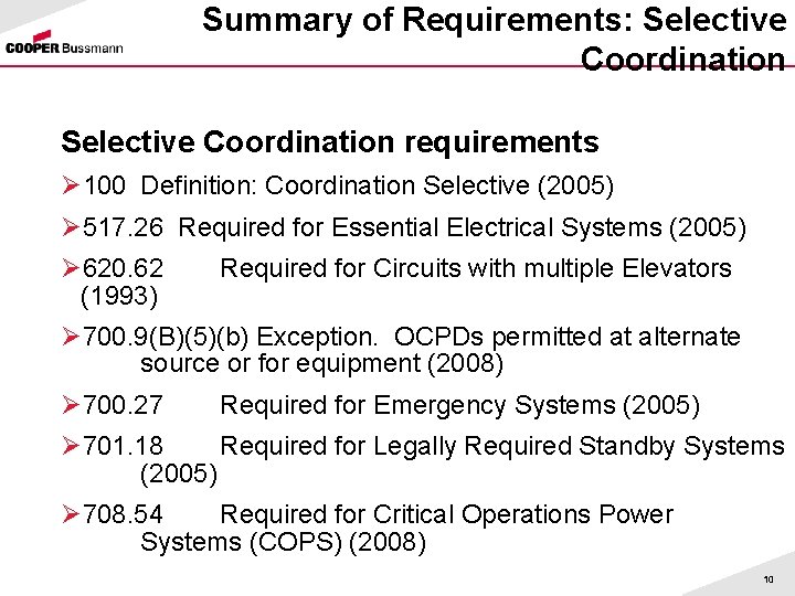
Summary of Requirements: Selective Coordination requirements Ø 100 Definition: Coordination Selective (2005) Ø 517. 26 Required for Essential Electrical Systems (2005) Ø 620. 62 (1993) Required for Circuits with multiple Elevators Ø 700. 9(B)(5)(b) Exception. OCPDs permitted at alternate source or for equipment (2008) Ø 700. 27 Required for Emergency Systems (2005) Ø 701. 18 Required for Legally Required Standby Systems (2005) Ø 708. 54 Required for Critical Operations Power Systems (COPS) (2008) 10
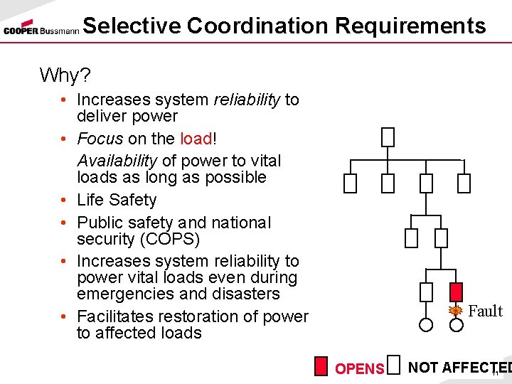
Selective Coordination Requirements Why? • Increases system reliability to deliver power • Focus on the load! Availability of power to vital loads as long as possible • Life Safety • Public safety and national security (COPS) • Increases system reliability to power vital loads even during emergencies and disasters • Facilitates restoration of power to affected loads Fault OPENS NOT AFFECTED 11
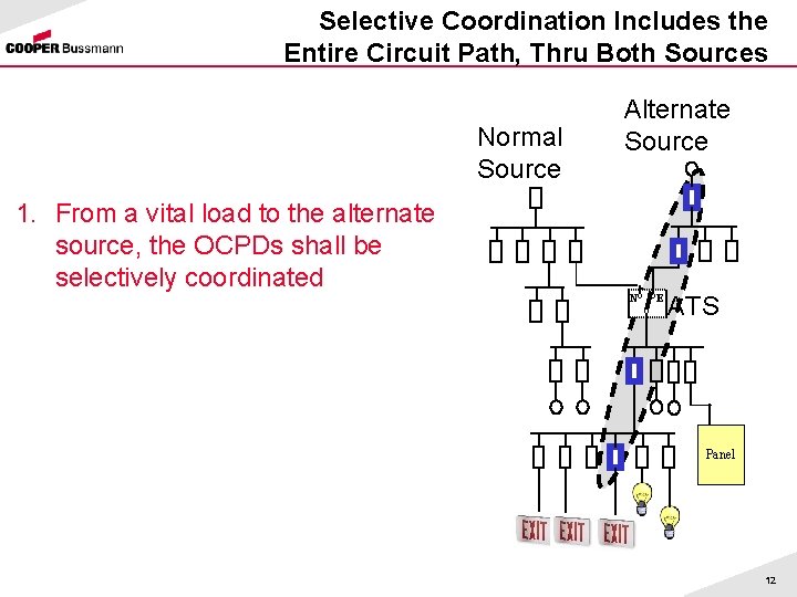
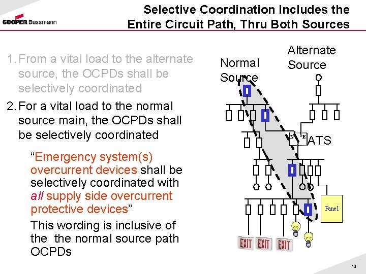
Selective Coordination Includes the Entire Circuit Path, Thru Both Sources Normal Source Alternate Source 1. From a vital load to the alternate source, the OCPDs shall be selectively coordinated N E ATS Panel 12
Selective Coordination Includes the Entire Circuit Path, Thru Both Sources 1. From a vital load to the alternate source, the OCPDs shall be selectively coordinated 2. For a vital load to the normal source main, the OCPDs shall be selectively coordinated “Emergency system(s) overcurrent devices shall be selectively coordinated with all supply side overcurrent protective devices” This wording is inclusive of the normal source path OCPDs Normal Source Alternate Source N E ATS Panel 13
Selective Coordination Requirements Ø NEC® 620. 62 Elevator Circuits (since 1993) – Requires selective coordination on circuit paths when multiple elevators are on a feeder. Required since 1993 to ensure safety of human life especially during emergency egress Ø Purpose of this requirement? – Maximize continuity of service – Quicker restoration of power 14
How to Selectively Coordinate with Fuses? Let’s take a look at what it takes to selectively coordinate fuses 15
Selective Coordination- Fuses 1200 A Fuse Melting LINE SIDE KRP-C 1200 SP Tm LOAD SIDE Tc LPS-RK 600 SP 1200 A fuse melting energy must be greater than 600 A fuse clearing energy AVAILABLE SHORTCIRCUIT CURRENT 600 A Fuse Clearing Tc 16
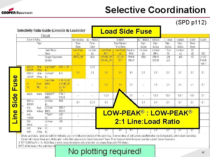
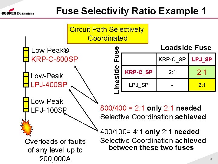
Selective Coordination (SPD p 112) Line Side Fuse Load Side Fuse LOW-PEAK® : LOW-PEAK® 2: 1 Line: Load Ratio No plotting required! 17
Fuse Selectivity Ratio Example 1 Low-Peak® KRP-C-800 SP Low-Peak LPJ-400 SP Low-Peak LPJ-100 SP Overloads or faults of any level up to 200, 000 A Lineside Fuse Circuit Path Selectively Coordinated Loadside Fuse KRP-C_SP LPJ_SP KRP-C_SP 2: 1 LPJ_SP - 2: 1 800/400 = 2: 1 only 2: 1 needed Selective Coordination achieved 400/100= 4: 1 only 2: 1 needed Selective Coordination achieved between these two fuses 18
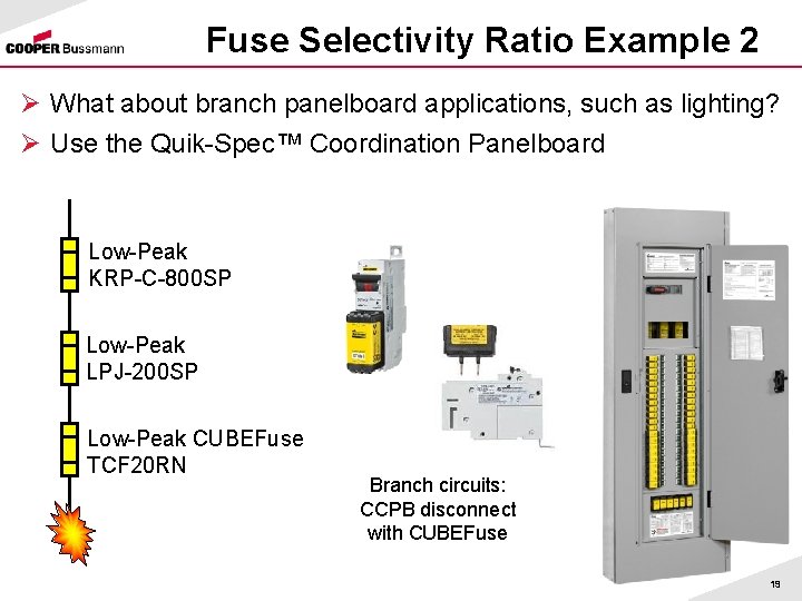
Fuse Selectivity Ratio Example 2 Ø What about branch panelboard applications, such as lighting? Ø Use the Quik-Spec™ Coordination Panelboard Low-Peak KRP-C-800 SP Low-Peak LPJ-200 SP Low-Peak CUBEFuse TCF 20 RN Branch circuits: CCPB disconnect with CUBEFuse 19
Benefits of Fuse Selective Coordination It is simple with Cooper Bussmann fuses Ø Just follow the fuse selectivity ratios: 2: 1 for Low-Peak® Fuses Ø No need to do complex short-circuit current studies (up to 200 k. A) Ø No need to plot time-current curves to analyze fuse selective coordination: use the selectivity ratios Ø In addition: – – High interrupting rating Excellent current-limitation Excellent protection of components Arc flash mitigation 20
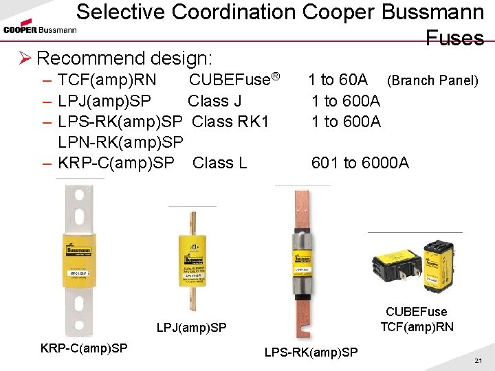
Selective Coordination Cooper Bussmann Fuses Ø Recommend design: – TCF(amp)RN CUBEFuse® – LPJ(amp)SP Class J – LPS-RK(amp)SP Class RK 1 LPN-RK(amp)SP – KRP-C(amp)SP Class L 1 to 60 A (Branch Panel) 1 to 600 A 601 to 6000 A CUBEFuse TCF(amp)RN LPJ(amp)SP KRP-C(amp)SP LPS-RK(amp)SP 21
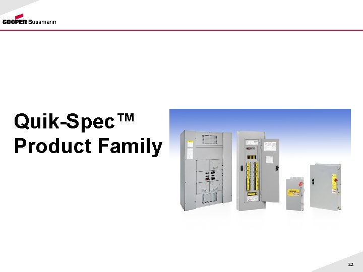
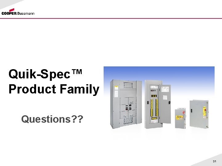
Quik-Spec™ Product Family 22
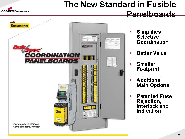
The New Standard in Fusible Panelboards • Simplifies Selective Coordination • Better Value • Smaller Footprint • Additional Main Options • Patented Fuse Rejection, Interlock and Indication 23
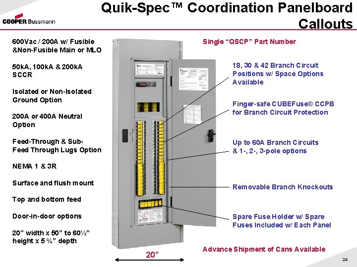
Quik-Spec™ Coordination Panelboard Callouts Single “QSCP” Part Number 600 Vac / 200 A w/ Fusible &Non-Fusible Main or MLO 18, 30 & 42 Branch Circuit Positions w/ Space Options Available 50 k. A, 100 k. A & 200 k. A SCCR Isolated or Non-Isolated Ground Option Finger-safe CUBEFuse® CCPB for Branch Circuit Protection 200 A or 400 A Neutral Option Feed-Through & Sub. Feed Through Lugs Option Up to 60 A Branch Circuits & 1 -, 2 -, 3 -pole options NEMA 1 & 3 R Surface and flush mount Removable Branch Knockouts Top and bottom feed Door-in-door options Spare Fuse Holder w/ Spare Fuses Included w/ Each Panel 20” width x 50” to 60½” height x 5 ¾” depth 20” Advance Shipment of Cans Available 24
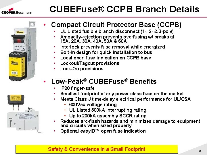
CUBEFuse® CCPB Branch Details • Compact Circuit Protector Base (CCPB) • • UL Listed fusible branch disconnect (1 -, 2 - & 3 -pole) Ampacity-rejection prevents overfusing w/ breaks at 15 A, 20 A, 30 A, 40 A, 50 A & 60 A Interlock prevents fuse removal while energized Bolt-in design for quick installation to bus Local open fuse indication on CCPB base Lockout/Tagout provisions Lock-On provisions • Low-Peak® CUBEFuse® Benefits • • • IP 20 finger-safe Smallest footprint of any power class fuse on the market Meets Class J time-delay electrical performance for UL/CSA • 600 Vac voltage rating • UL Listed 300 k. A interrupting rating • Up to 200 k. A assembly SCCR rating Reduces arc-flash hazards and minimizes damage to equipment and circuits when sized properly Optional easy. ID™ open fuse indication Safety & Convenience in a Small Footprint 25
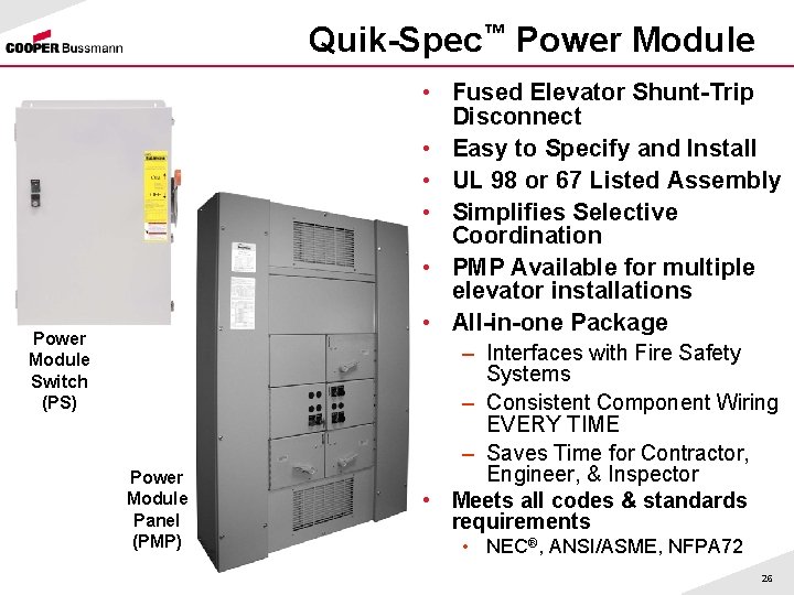
Quik-Spec™ Power Module • Fused Elevator Shunt-Trip Disconnect • Easy to Specify and Install • UL 98 or 67 Listed Assembly • Simplifies Selective Coordination • PMP Available for multiple elevator installations • All-in-one Package Power Module Switch (PS) Power Module Panel (PMP) – Interfaces with Fire Safety Systems – Consistent Component Wiring EVERY TIME – Saves Time for Contractor, Engineer, & Inspector • Meets all codes & standards requirements • NEC®, ANSI/ASME, NFPA 72 26
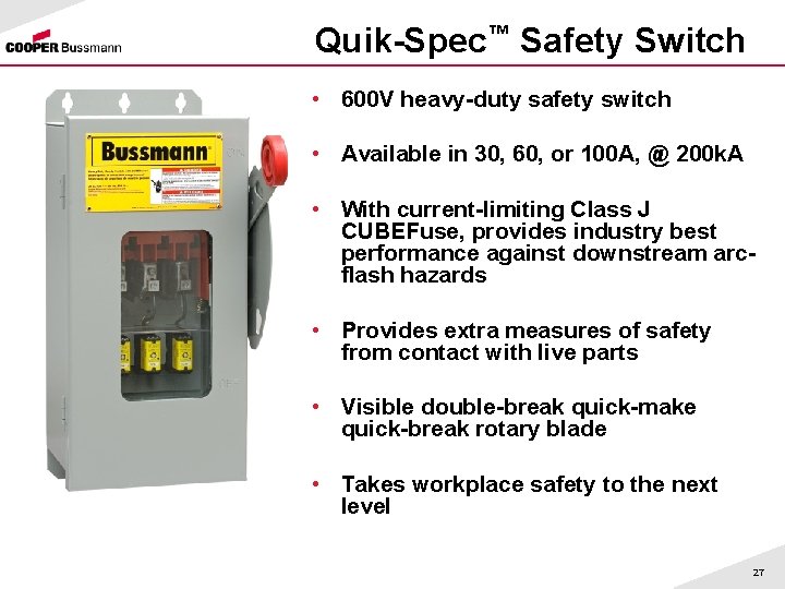
Quik-Spec™ Safety Switch • 600 V heavy-duty safety switch • Available in 30, 60, or 100 A, @ 200 k. A • With current-limiting Class J CUBEFuse, provides industry best performance against downstream arcflash hazards • Provides extra measures of safety from contact with live parts • Visible double-break quick-make quick-break rotary blade • Takes workplace safety to the next level 27
Resources Ø Quik-Spec Products – – Product profiles Data sheets Application Notes for QS Coordination Panel Flash Demo Ø Low-Peak® fuse datasheets Ø Selective coordination technical discussion (SPD) – How to – Selectivity Ratio Guide – SPD selective coordination section download Ø Voiceover Power. Point: Why Selective Coordination Ø Third party articles on Selective Coordination Ø www. Cooper. Bussmann. com 28
PTP Tour Special Offer Ø 1 -Year, No Cost Subscription to OSCAR™ 2. 0 Compliance Software ØSpeeds Code & Agency Marking Requirements ØThis award winning, online, essential design tool allows you to comply quickly and accurately with 2008 NEC® and UL 508 A Supplement SB for assembly SCCR marking requirements: Ø • Industrial Control Panels [409. 110] Ø • Industrial Machinery Electrical Panels [670. 3(A)] Ø • HVAC Equipment [440. 4(B)] ØNew Project Management Features: Ø • Simplify your panel design and project organization. Ø • Save and edit existing panel designs. Ø • Save multiple panels under a single project. Ø • Copy existing panels to new projects. ØNew Intuitive Navigation: Ø • Display your one-line diagram. Ø • Select from pre-loaded circuit templates. Ø • Identify the weakest link component automatically. Ø • Print reports and one-line diagrams for required SCCR documentation. Ø • Utilize mouse-over tips to enhance your design. ØDesign with Confidence: Ø • Logic updated to current UL requirements. Ø • Search by partial part number or device rating. • Extensive 55, 000+ component database. • Custom device option allows for entering specialized component rating information. ØGet Your 1 -Year, No Cost Subscription ØBe sure to register for this presentation and include your e-mail address. ØDetails will be e-mailed to you within 7 to 10 business days. 29
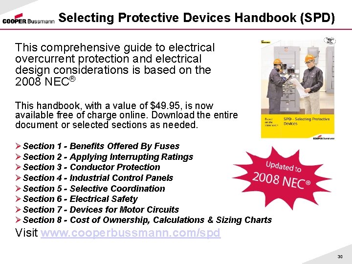
Selecting Protective Devices Handbook (SPD) This comprehensive guide to electrical overcurrent protection and electrical design considerations is based on the 2008 NEC® This handbook, with a value of $49. 95, is now available free of charge online. Download the entire document or selected sections as needed. ØSection 1 - Benefits Offered By Fuses ØSection 2 - Applying Interrupting Ratings ØSection 3 - Conductor Protection ØSection 4 - Industrial Control Panels ØSection 5 - Selective Coordination ØSection 6 - Electrical Safety ØSection 7 - Devices for Motor Circuits ØSection 8 - Cost of Ownership, Calculations & Sizing Charts Visit www. cooperbussmann. com/spd 30
Quik-Spec™ Product Family Questions? ? 31