Removing The Ideal Memory Assumption The Memory Hierarchy
- Slides: 52
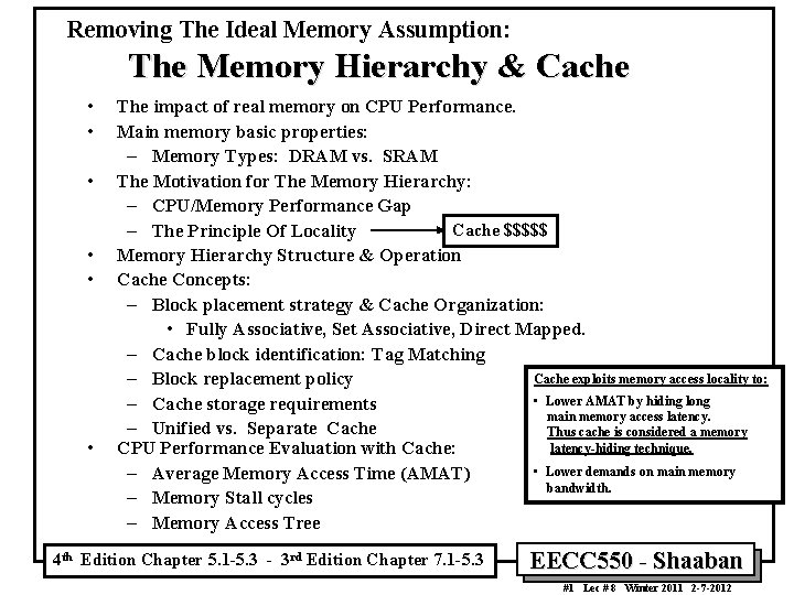
Removing The Ideal Memory Assumption: The Memory Hierarchy & Cache • • • The impact of real memory on CPU Performance. Main memory basic properties: – Memory Types: DRAM vs. SRAM The Motivation for The Memory Hierarchy: – CPU/Memory Performance Gap Cache $$$$$ – The Principle Of Locality Memory Hierarchy Structure & Operation Cache Concepts: – Block placement strategy & Cache Organization: • Fully Associative, Set Associative, Direct Mapped. – Cache block identification: Tag Matching Cache exploits memory access locality to: – Block replacement policy • Lower AMAT by hiding long – Cache storage requirements main memory access latency. – Unified vs. Separate Cache Thus cache is considered a memory latency-hiding technique. CPU Performance Evaluation with Cache: • Lower demands on main memory – Average Memory Access Time (AMAT) bandwidth. – Memory Stall cycles – Memory Access Tree 4 th Edition Chapter 5. 1 -5. 3 - 3 rd Edition Chapter 7. 1 -5. 3 EECC 550 - Shaaban #1 Lec # 8 Winter 2011 2 -7 -2012
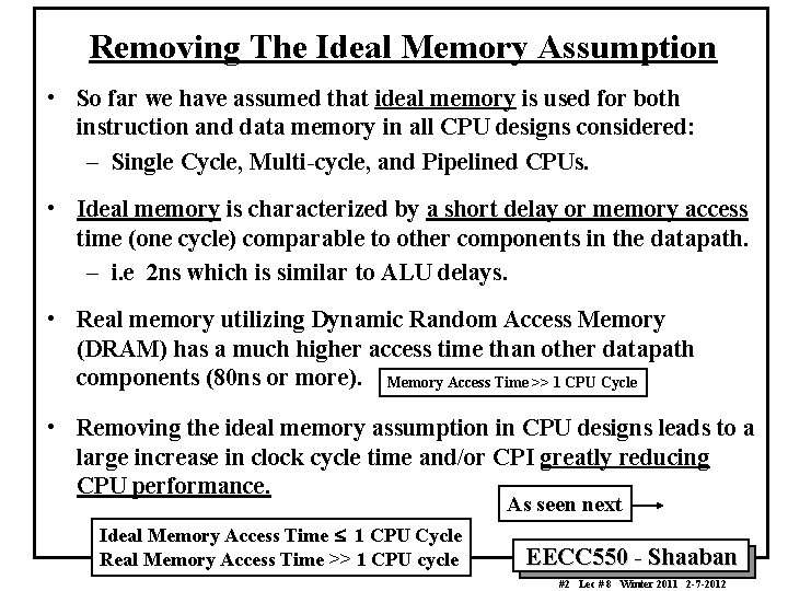
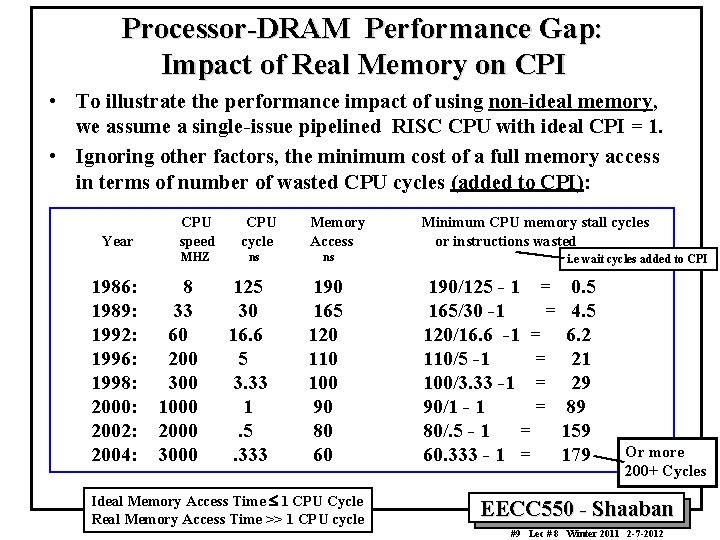
Removing The Ideal Memory Assumption • So far we have assumed that ideal memory is used for both instruction and data memory in all CPU designs considered: – Single Cycle, Multi-cycle, and Pipelined CPUs. • Ideal memory is characterized by a short delay or memory access time (one cycle) comparable to other components in the datapath. – i. e 2 ns which is similar to ALU delays. • Real memory utilizing Dynamic Random Access Memory (DRAM) has a much higher access time than other datapath components (80 ns or more). Memory Access Time >> 1 CPU Cycle • Removing the ideal memory assumption in CPU designs leads to a large increase in clock cycle time and/or CPI greatly reducing CPU performance. As seen next Ideal Memory Access Time £ 1 CPU Cycle Real Memory Access Time >> 1 CPU cycle EECC 550 - Shaaban #2 Lec # 8 Winter 2011 2 -7 -2012
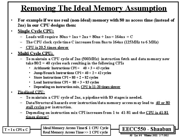
Removing The Ideal Memory Assumption • • For example if we use real (non-ideal) memory with 80 ns access time (instead of 2 ns) in our CPU designs then: Single Cycle CPU: – Loads will require 80 ns + 1 ns + 2 ns + 80 ns + 1 ns = 164 ns = C – The CPU clock cycle time C increases from 8 ns to 164 ns (125 MHz to 6 MHz) – CPU is 20. 5 times slower • Multi Cycle CPU: – To maintain a CPU cycle of 2 ns (500 MHz) instruction fetch and data memory now take 80/2 = 40 cycles each resulting in the following CPIs • • • Arithmetic Instructions CPI = 40 + 3 = 43 cycles Jump/Branch Instructions CPI = 40 + 2 = 42 cycles Store Instructions CPI = 80 + 2 = 82 cycles Load Instructions CPI = 80 + 3 = 83 cycles Depending on instruction mix, CPU is 11 -20 times slower Pipelined CPU: – To maintain a CPU cycle of 2 ns, a pipeline with 83 stages is needed. – Data/Structural hazards over instruction/data memory access may lead to 40 or 80 stall cycles per instruction. – Depending on instruction mix CPI increases from 1 to 41 -81 and the CPU is 41 -81 times slower! T = I x CPI x C Ideal Memory Access Time £ 1 CPU Cycle Real Memory Access Time >> 1 CPU cycle EECC 550 - Shaaban #3 Lec # 8 Winter 2011 2 -7 -2012
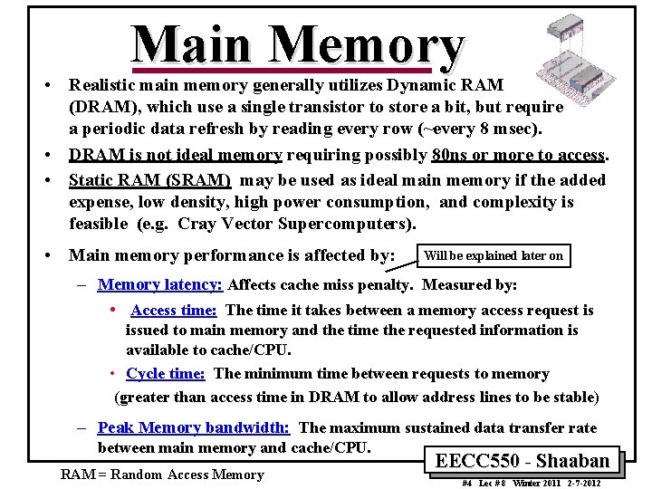
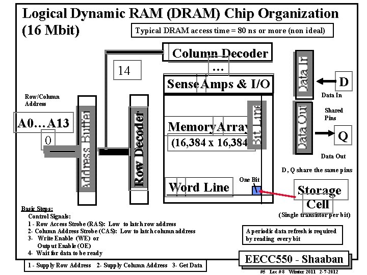
Main Memory • Realistic main memory generally utilizes Dynamic RAM (DRAM), which use a single transistor to store a bit, but require a periodic data refresh by reading every row (~every 8 msec). • DRAM is not ideal memory requiring possibly 80 ns or more to access. • Static RAM (SRAM) may be used as ideal main memory if the added expense, low density, high power consumption, and complexity is feasible (e. g. Cray Vector Supercomputers). • Main memory performance is affected by: Will be explained later on – Memory latency: Affects cache miss penalty. Measured by: • Access time: The time it takes between a memory access request is issued to main memory and the time the requested information is available to cache/CPU. • Cycle time: The minimum time between requests to memory (greater than access time in DRAM to allow address lines to be stable) – Peak Memory bandwidth: The maximum sustained data transfer rate between main memory and cache/CPU. RAM = Random Access Memory EECC 550 - Shaaban #4 Lec # 8 Winter 2011 2 -7 -2012
Logical Dynamic RAM (DRAM) Chip Organization Typical DRAM access time = 80 ns or more (non ideal) (16 Mbit) Column Decoder … Sense Amps & I/O 14 Data In Row Decoder Row/Column Address A 0…A 13 0 Memory Array Shared Pins Q (16, 384 x 16, 384) Data Out D, Q share the same pins Word Line Basic Steps: Control Signals: 1 - Row Access Strobe (RAS): Low to latch row address 2 - Column Address Strobe (CAS): Low to latch column address 3 - Write Enable (WE) or Output Enable (OE) 4 - Wait for data to be ready 1 - Supply Row Address D 2 - Supply Column Address 3 - Get Data One Bit Storage Cell (Single transistor per bit) A periodic data refresh is required by reading every bit EECC 550 - Shaaban #5 Lec # 8 Winter 2011 2 -7 -2012
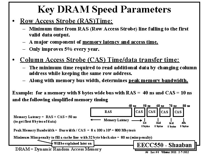
Key DRAM Speed Parameters • Row Access Strobe (RAS)Time: – Minimum time from RAS (Row Access Strobe) line falling to the first valid data output. – A major component of memory latency and access time. – Only improves 5% every year. • Column Access Strobe (CAS) Time/data transfer time: – The minimum time required to read additional data by changing column address while keeping the same row address. – Along with memory bus width, determines peak memory bandwidth. Example: for a memory with 8 bytes wide bus with RAS = 40 ns and CAS = 10 ns and the following simplified memory timing 40 ns RAS Memory Latency = RAS + CAS = 50 ns (to get first 8 bytes of data) 50 ns CAS Memory Latency 60 ns CAS 1 st 8 bytes CAS 70 ns 2 nd 8 bytes 80 ns CAS 3 rd 8 bytes 4 th 8 bytes Peak Memory Bandwidth = Bus width / CAS = 8 x 100 x 106 = 800 Mbytes/s Minimum Miss penalty to fill a cache line with 32 byte block size = 80 ns (miss penalty) Will be explained later on DRAM = Dynamic Random Access Memory EECC 550 - Shaaban #6 Lec # 8 Winter 2011 2 -7 -2012
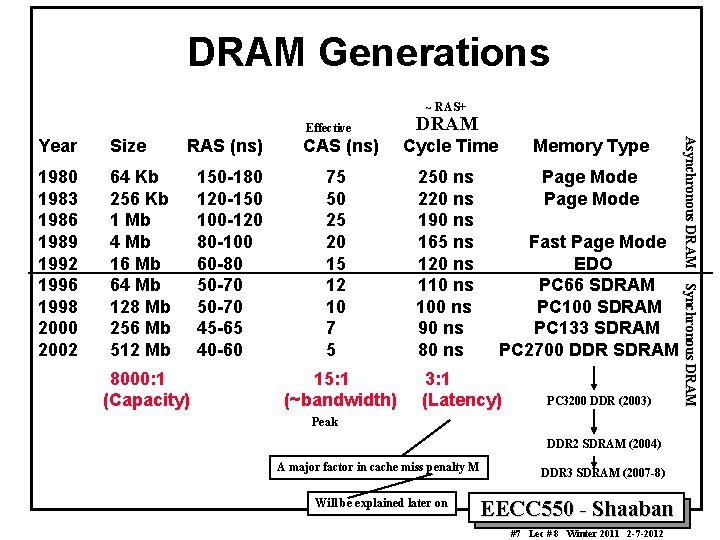
DRAM Generations ~ RAS+ Effective Size 1980 1983 1986 1989 1992 1996 1998 2000 2002 64 Kb 256 Kb 1 Mb 4 Mb 16 Mb 64 Mb 128 Mb 256 Mb 512 Mb RAS (ns) CAS (ns) 150 -180 120 -150 100 -120 80 -100 60 -80 50 -70 45 -65 40 -60 75 50 25 20 15 12 10 7 5 8000: 1 (Capacity) 15: 1 (~bandwidth) Cycle Time 250 ns 220 ns 190 ns 165 ns 120 ns 110 ns 100 ns 90 ns 80 ns Memory Type Page Mode Fast Page Mode EDO PC 66 SDRAM PC 100 SDRAM PC 133 SDRAM PC 2700 DDR SDRAM 3: 1 (Latency) PC 3200 DDR (2003) Peak DDR 2 SDRAM (2004) A major factor in cache miss penalty M Will be explained later on DDR 3 SDRAM (2007 -8) EECC 550 - Shaaban #7 Lec # 8 Winter 2011 2 -7 -2012 Asynchronous DRAM Synchronous DRAM Year DRAM
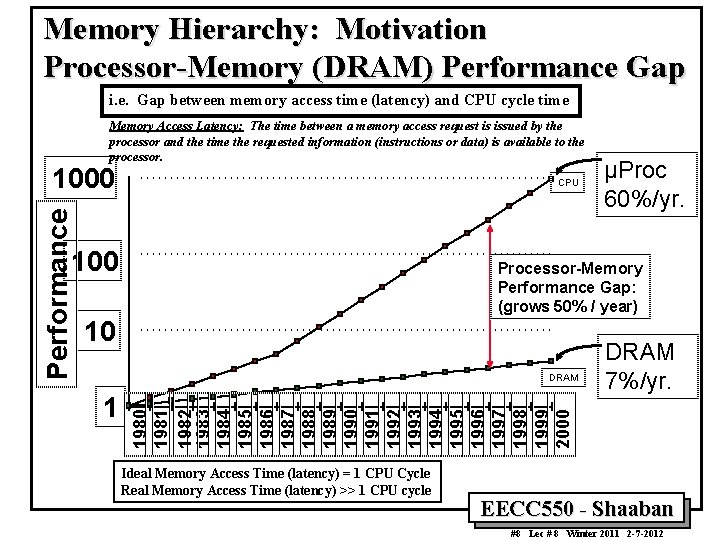
Memory Hierarchy: Motivation Processor-Memory (DRAM) Performance Gap i. e. Gap between memory access time (latency) and CPU cycle time Memory Access Latency: The time between a memory access request is issued by the processor and the time the requested information (instructions or data) is available to the processor. Performance 1000 CPU 100 Processor-Memory Performance Gap: (grows 50% / year) 10 DRAM 7%/yr. 1980 1981 1982 1983 1984 1985 1986 1987 1988 1989 1990 1991 1992 1993 1994 1995 1996 1997 1998 1999 2000 DRAM 1 µProc 60%/yr. Ideal Memory Access Time (latency) = 1 CPU Cycle Real Memory Access Time (latency) >> 1 CPU cycle EECC 550 - Shaaban #8 Lec # 8 Winter 2011 2 -7 -2012
Processor-DRAM Performance Gap: Impact of Real Memory on CPI • To illustrate the performance impact of using non-ideal memory, we assume a single-issue pipelined RISC CPU with ideal CPI = 1. • Ignoring other factors, the minimum cost of a full memory access in terms of number of wasted CPU cycles (added to CPI): Year CPU speed MHZ 1986: 8 1989: 33 1992: 60 1996: 200 1998: 300 2000: 1000 2002: 2000 2004: 3000 CPU cycle ns 125 30 16. 6 5 3. 33 1. 5. 333 Memory Access ns 190 165 120 110 100 90 80 60 Ideal Memory Access Time £ 1 CPU Cycle Real Memory Access Time >> 1 CPU cycle Minimum CPU memory stall cycles or instructions wasted i. e wait cycles added to CPI 190/125 - 1 = 0. 5 165/30 -1 = 4. 5 120/16. 6 -1 = 6. 2 110/5 -1 = 21 100/3. 33 -1 = 29 90/1 - 1 = 89 80/. 5 - 1 = 159 60. 333 - 1 = 179 Or more 200+ Cycles EECC 550 - Shaaban #9 Lec # 8 Winter 2011 2 -7 -2012
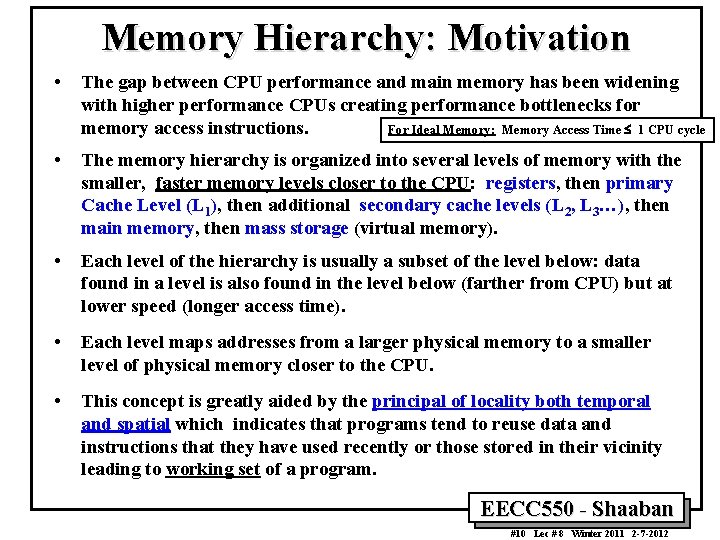
Memory Hierarchy: Motivation • The gap between CPU performance and main memory has been widening with higher performance CPUs creating performance bottlenecks for memory access instructions. For Ideal Memory: Memory Access Time £ 1 CPU cycle • The memory hierarchy is organized into several levels of memory with the smaller, faster memory levels closer to the CPU: registers, then primary Cache Level (L 1), then additional secondary cache levels (L 2, L 3…), then main memory, then mass storage (virtual memory). • Each level of the hierarchy is usually a subset of the level below: data found in a level is also found in the level below (farther from CPU) but at lower speed (longer access time). • Each level maps addresses from a larger physical memory to a smaller level of physical memory closer to the CPU. • This concept is greatly aided by the principal of locality both temporal and spatial which indicates that programs tend to reuse data and instructions that they have used recently or those stored in their vicinity leading to working set of a program. EECC 550 - Shaaban #10 Lec # 8 Winter 2011 2 -7 -2012
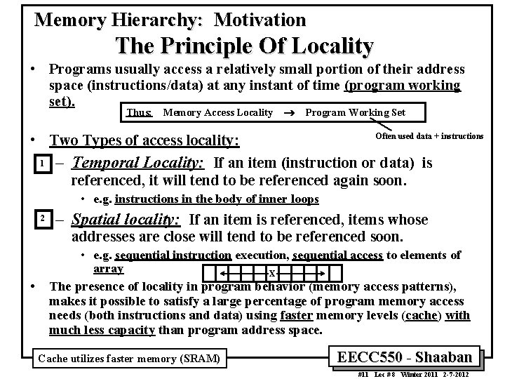
Memory Hierarchy: Motivation The Principle Of Locality • Programs usually access a relatively small portion of their address space (instructions/data) at any instant of time (program working set). Thus: Memory Access Locality ® Program Working Set Often used data + instructions • Two Types of access locality: 1 – Temporal Locality: If an item (instruction or data) is referenced, it will tend to be referenced again soon. • e. g. instructions in the body of inner loops 2 – Spatial locality: If an item is referenced, items whose addresses are close will tend to be referenced soon. • • e. g. sequential instruction execution, sequential access to elements of array X The presence of locality in program behavior (memory access patterns), makes it possible to satisfy a large percentage of program memory access needs (both instructions and data) using faster memory levels (cache) with much less capacity than program address space. Cache utilizes faster memory (SRAM) EECC 550 - Shaaban #11 Lec # 8 Winter 2011 2 -7 -2012
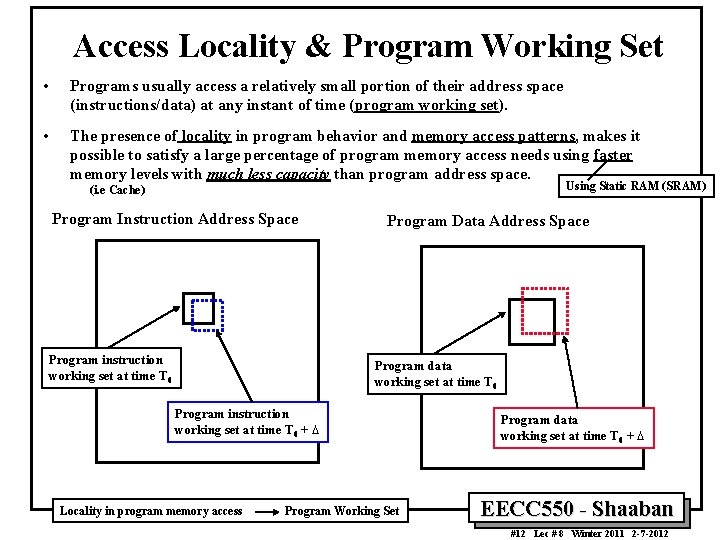
Access Locality & Program Working Set • Programs usually access a relatively small portion of their address space (instructions/data) at any instant of time (program working set). • The presence of locality in program behavior and memory access patterns, makes it possible to satisfy a large percentage of program memory access needs using faster memory levels with much less capacity than program address space. Using Static RAM (SRAM) (i. e Cache) Program Instruction Address Space Program instruction working set at time T 0 Program Data Address Space Program data working set at time T 0 Program instruction working set at time T 0 + D Locality in program memory access Program Working Set Program data working set at time T 0 + D EECC 550 - Shaaban #12 Lec # 8 Winter 2011 2 -7 -2012
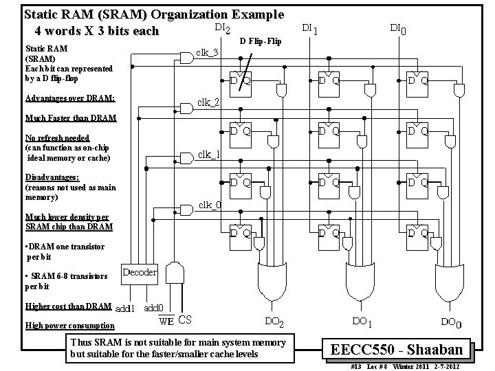
Static RAM (SRAM) Organization Example 4 words X 3 bits each Static RAM (SRAM) Each bit can represented by a D flip-flop D Flip-Flip Advantages over DRAM: Much Faster than DRAM No refresh needed (can function as on-chip ideal memory or cache) Disadvantages: (reasons not used as main memory) Much lower density per SRAM chip than DRAM • DRAM one transistor per bit • SRAM 6 -8 transistors per bit Higher cost than DRAM High power consumption Thus SRAM is not suitable for main system memory but suitable for the faster/smaller cache levels EECC 550 - Shaaban #13 Lec # 8 Winter 2011 2 -7 -2012
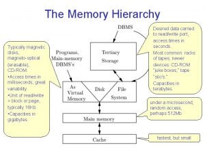
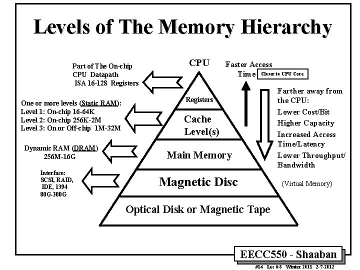
Levels of The Memory Hierarchy Part of The On-chip CPU Datapath ISA 16 -128 Registers One or more levels (Static RAM): Level 1: On-chip 16 -64 K Level 2: On-chip 256 K-2 M Level 3: On or Off-chip 1 M-32 M Dynamic RAM (DRAM) 256 M-16 G Interface: SCSI, RAID, IDE, 1394 80 G-300 G CPU Faster Access Time Closer to CPU Core Farther away from the CPU: Lower Cost/Bit Higher Capacity Increased Access Time/Latency Lower Throughput/ Bandwidth Registers Cache Level(s) Main Memory Magnetic Disc (Virtual Memory) Optical Disk or Magnetic Tape EECC 550 - Shaaban #14 Lec # 8 Winter 2011 2 -7 -2012
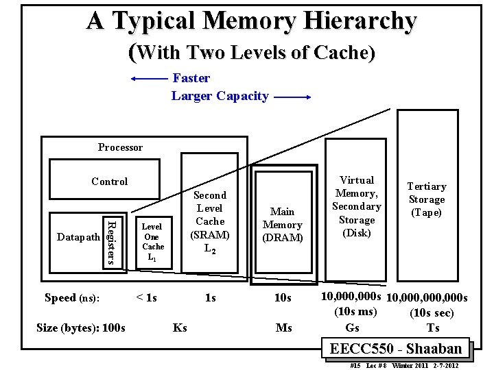
A Typical Memory Hierarchy (With Two Levels of Cache) Faster Larger Capacity Processor Control Registers Datapath Speed (ns): Size (bytes): 100 s Level One Cache L 1 < 1 s Ks Second Level Cache (SRAM) L 2 Main Memory (DRAM) 1 s 10 s Ms Virtual Memory, Secondary Storage (Disk) Tertiary Storage (Tape) 10, 000 s 10, 000, 000 s (10 s ms) (10 s sec) Gs Ts EECC 550 - Shaaban #15 Lec # 8 Winter 2011 2 -7 -2012
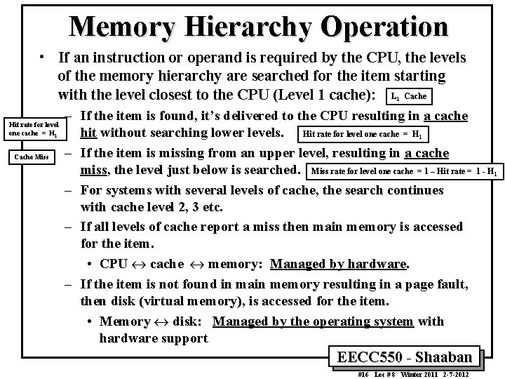
Memory Hierarchy Operation • If an instruction or operand is required by the CPU, the levels of the memory hierarchy are searched for the item starting with the level closest to the CPU (Level 1 cache): L Cache 1 Hit rate for level one cache = H 1 Cache Miss – If the item is found, it’s delivered to the CPU resulting in a cache hit without searching lower levels. Hit rate for level one cache = H – If the item is missing from an upper level, resulting in a cache miss, the level just below is searched. Miss rate for level one cache = 1 – Hit rate = 1 - H – For systems with several levels of cache, the search continues with cache level 2, 3 etc. – If all levels of cache report a miss then main memory is accessed for the item. • CPU « cache « memory: Managed by hardware. – If the item is not found in main memory resulting in a page fault, then disk (virtual memory), is accessed for the item. • Memory « disk: Managed by the operating system with hardware support 1 EECC 550 - Shaaban #16 Lec # 8 Winter 2011 2 -7 -2012 1
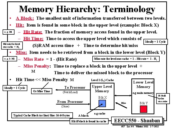
Memory Hierarchy: Terminology • A Block: The smallest unit of information transferred between two levels. • Hit: Item is found in some block in the upper level (example: Block X) e. g. H 1 – Hit Rate: The fraction of memory access found in the upper level. – Hit Time: Time to access the upper level which consists of Ideally = 1 Cycle Hit rate for level (S) RAM access time + Time to determine hit/miss one cache = H • Miss: Item needs to be retrieved from a block in the lower level (Block Y) e. g. 1 - H 1 – Miss Rate = 1 - (Hit Rate) Miss rate for level one cache = 1 – Hit rate = 1 - H – Miss Penalty: Time to replace a block in the upper level + M Time to deliver the missed block to the processor Level 1 (L ) Cache • Hit Time << Miss Penalty M Lower Level 1 1 1 To Processor Ideally = 1 Cycle Or Miss Time (Fetch/Load) Upper Level Memory e. g main memory Blk X From Processor Miss (Store) Typical Cache Block (or line) Size: 16 -64 bytes A block Blk Y M Stall cycles on a miss e. g cache Hit if block is found in cache EECC 550 - Shaaban #17 Lec # 8 Winter 2011 2 -7 -2012
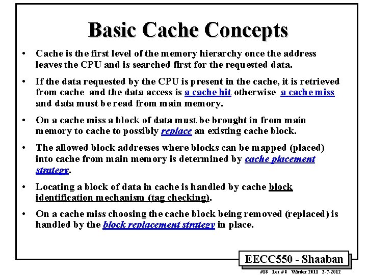
Basic Cache Concepts • Cache is the first level of the memory hierarchy once the address leaves the CPU and is searched first for the requested data. • If the data requested by the CPU is present in the cache, it is retrieved from cache and the data access is a cache hit otherwise a cache miss and data must be read from main memory. • On a cache miss a block of data must be brought in from main memory to cache to possibly replace an existing cache block. • The allowed block addresses where blocks can be mapped (placed) into cache from main memory is determined by cache placement strategy. • Locating a block of data in cache is handled by cache block identification mechanism (tag checking). • On a cache miss choosing the cache block being removed (replaced) is handled by the block replacement strategy in place. EECC 550 - Shaaban #18 Lec # 8 Winter 2011 2 -7 -2012
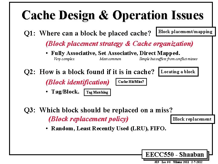
Cache Design & Operation Issues Q 1: Where can a block be placed cache? Block placement/mapping (Block placement strategy & Cache organization) • Fully Associative, Set Associative, Direct Mapped. Very complex Most common Simple but suffers from conflict misses Q 2: How is a block found if it is in cache? (Block identification) Cache Hit/Miss? • Tag/Block. Locating a block Tag Matching Q 3: Which block should be replaced on a miss? Block replacement (Block replacement policy) • Random, Least Recently Used (LRU), FIFO. EECC 550 - Shaaban #19 Lec # 8 Winter 2011 2 -7 -2012
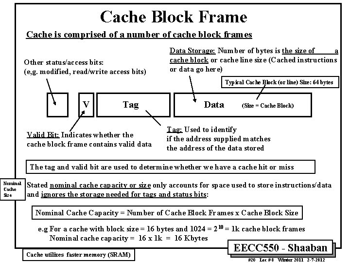
Cache Block Frame Cache is comprised of a number of cache block frames Other status/access bits: (e, g. modified, read/write access bits) Data Storage: Number of bytes is the size of a cache block or cache line size (Cached instructions or data go here) Typical Cache Block (or line) Size: 64 bytes V Tag Valid Bit: Indicates whether the cache block frame contains valid data Data (Size = Cache Block) Tag: Used to identify if the address supplied matches the address of the data stored The tag and valid bit are used to determine whether we have a cache hit or miss Nominal Cache Size Stated nominal cache capacity or size only accounts for space used to store instructions/data and ignores the storage needed for tags and status bits: Nominal Cache Capacity = Number of Cache Block Frames x Cache Block Size e. g For a cache with block size = 16 bytes and 1024 = 210 = 1 k cache block frames Nominal cache capacity = 16 x 1 k = 16 Kbytes Cache utilizes faster memory (SRAM) EECC 550 - Shaaban #20 Lec # 8 Winter 2011 2 -7 -2012
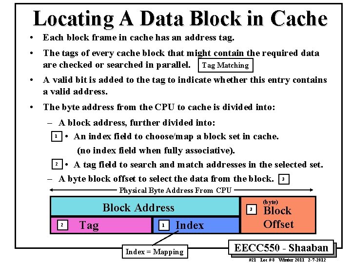
Locating A Data Block in Cache • Each block frame in cache has an address tag. • The tags of every cache block that might contain the required data are checked or searched in parallel. Tag Matching • A valid bit is added to the tag to indicate whether this entry contains a valid address. • The byte address from the CPU to cache is divided into: – A block address, further divided into: 1 • An index field to choose/map a block set in cache. (no index field when fully associative). 2 • A tag field to search and match addresses in the selected set. – A byte block offset to select the data from the block. 3 Physical Byte Address From CPU (byte) Block Address 2 Tag 1 3 Index = Mapping Block Offset EECC 550 - Shaaban #21 Lec # 8 Winter 2011 2 -7 -2012
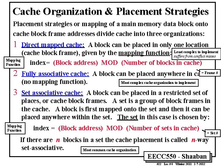
Cache Organization & Placement Strategies Placement strategies or mapping of a main memory data block onto cache block frame addresses divide cache into three organizations: 1 Direct mapped cache: A block can be placed in only one location complex to implement (cache block frame), given by the mapping function: Least suffers from conflict misses Mapping index= (Block address) MOD (Number of blocks in cache) Function 2 3 = Frame # Fully associative cache: A block can be placed anywhere in cache. (no mapping function). Most complex cache organization to implement Set associative cache: A block can be placed in a restricted set of places, or cache block frames. A set is a group of block frames in the cache. A block is first mapped onto the set and then it can be placed anywhere within the set. The set in this case is chosen by: Mapping Function index = (Block address) MOD (Number of sets in cache) = Set # If there are n blocks in a set the cache placement is called n-way set-associative. Most common cache organization EECC 550 - Shaaban #22 Lec # 8 Winter 2011 2 -7 -2012
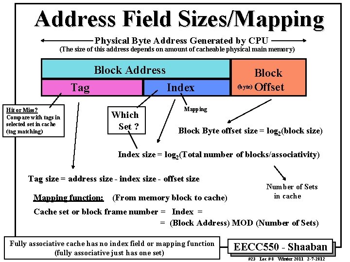
Address Field Sizes/Mapping Physical Byte Address Generated by CPU (The size of this address depends on amount of cacheable physical main memory) Block Address Tag Hit or Miss? Compare with tags in selected set in cache (tag matching) Index Which Set ? Block (byte) Offset Mapping Block Byte offset size = log 2(block size) Index size = log 2(Total number of blocks/associativity) Tag size = address size - index size - offset size Mapping function: (From memory block to cache) Number of Sets in cache Cache set or block frame number = Index = = (Block Address) MOD (Number of Sets) Fully associative cache has no index field or mapping function (fully associative just has one set) EECC 550 - Shaaban #23 Lec # 8 Winter 2011 2 -7 -2012
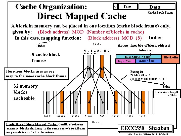
Cache Organization: Tag V Data Direct Mapped Cache Block Frame A block in memory can be placed in one location (cache block frame) only, given by: (Block address) MOD (Number of blocks in cache) In this case, mapping function: (Block address) MOD (8) = Index 110 (i. e low three bits of block address) Index bits 111 100 101 010 000 8 cache block frames 011 C a ch e Index Block Address = 5 bits Tag = 2 bits Here four blocks in memory map to the same cache block frame Block offset Index = 3 bits Example: 29 MOD 8 = 5 (11101) MOD (1000) = 101 32 memory blocks cacheable index Index size = Log 2 8 = 3 bits 00 001 0 0101 0100 1 01101 Limitation of Direct Mapped Cache: Conflicts between memory blocks that map to the same cache block frame may result in conflict cache misses 1000 1 101 01 11 00 1 11101 M e m o ry EECC 550 - Shaaban #24 Lec # 8 Winter 2011 2 -7 -2012
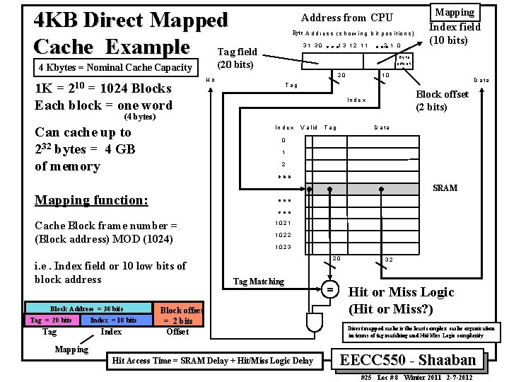
4 KB Direct Mapped Cache Example Tag field 1 K = 210 = 1024 Blocks Each block = one word Byte A d d r e s s ( s h o w i n g b it p o s i tio n s ) 31 30 13 12 11 2 1 0 o ffs e t 10 20 H it Block offset (2 bits) In d e x V a l id T ag D a ta 0 1 2 SRAM Mapping function: Cache Block frame number = (Block address) MOD (1024) i. e. Index field or 10 low bits of block address Block Address = 30 bits Tag = 20 bits Tag Index = 10 bits Index D a ta Tag (4 bytes) Can cache up to 232 bytes = 4 GB of memory Index field (10 bits) B y te (20 bits) 4 Kbytes = Nominal Cache Capacity Mapping Address from CPU 1021 1022 1023 20 Tag Matching Block offset = 2 bits Offset Mapping Hit Access Time = SRAM Delay + Hit/Miss Logic Delay 32 Hit or Miss Logic (Hit or Miss? ) Direct mapped cache is the least complex cache organization in terms of tag matching and Hit/Miss Logic complexity EECC 550 - Shaaban #25 Lec # 8 Winter 2011 2 -7 -2012
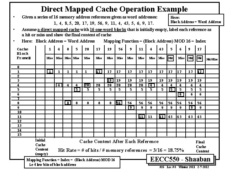
Direct Mapped Cache Operation Example • Given a series of 16 memory address references given as word addresses: Here: Block Address = Word Address 1, 4, 8, 5, 20, 17, 19, 56, 9, 11, 4, 43, 5, 6, 9, 17. Assume a direct mapped cache with 16 one-word blocks that is initially empty, label each reference as a hit or miss and show the final content of cache Here: Block Address = Word Address Mapping Function = (Block Address) MOD 16 = Index • • Cache Block Frame# 1 Miss 0 1 2 3 4 5 6 7 8 9 10 11 12 13 14 15 1 Initial Cache Content (empty) 4 8 5 Miss 20 17 19 56 9 11 Miss Miss 43 5 Miss Hit 6 Miss 9 17 Hit 1 1 17 17 17 4 4 4 5 20 5 19 20 5 19 4 5 6 19 4 5 6 8 8 8 56 56 9 56 9 11 11 43 43 43 Cache Content After Each Reference Hit Rate = # of hits / # memory references = 3/16 = 18. 75% Mapping Function = Index = (Block Address) MOD 16 i. e 4 low bits of block address Hit/Miss Final Cache Content EECC 550 - Shaaban #26 Lec # 8 Winter 2011 2 -7 -2012
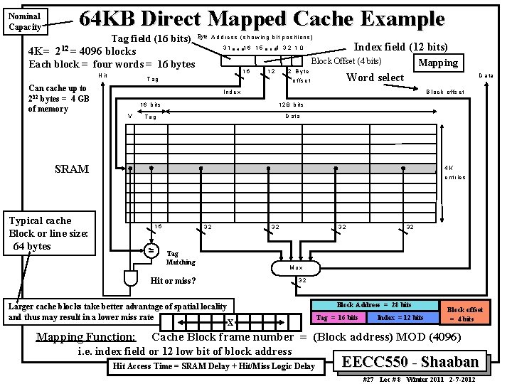
Nominal Capacity 64 KB Direct Mapped Cache Example Tag field (16 bits) Byte A d d re s s (s h o w in g b it p o s iti o n s ) 4 K= 212 = 4096 blocks 31 Can cache up to 232 bytes = 4 GB of memory Index field (12 bits) 4 32 1 0 Block Offset (4 bits) Each block = four words = 16 bytes H it 16 1 5 16 12 2 B y te T ag Mapping Word select o ffs e t D a ta In d e x V B lo c k o f fs e t 1 6 b its 1 2 8 b its T ag D a ta SRAM 4 K e n trie s Typical cache Block or line size: 64 bytes 16 32 32 Tag Matching 32 Mux Hit or miss? Larger cache blocks take better advantage of spatial locality and thus may result in a lower miss rate Mapping Function: 32 32 Block Address = 28 bits X Tag = 16 bits Index = 12 bits Block offset = 4 bits Cache Block frame number = (Block address) MOD (4096) i. e. index field or 12 low bit of block address Hit Access Time = SRAM Delay + Hit/Miss Logic Delay EECC 550 - Shaaban #27 Lec # 8 Winter 2011 2 -7 -2012
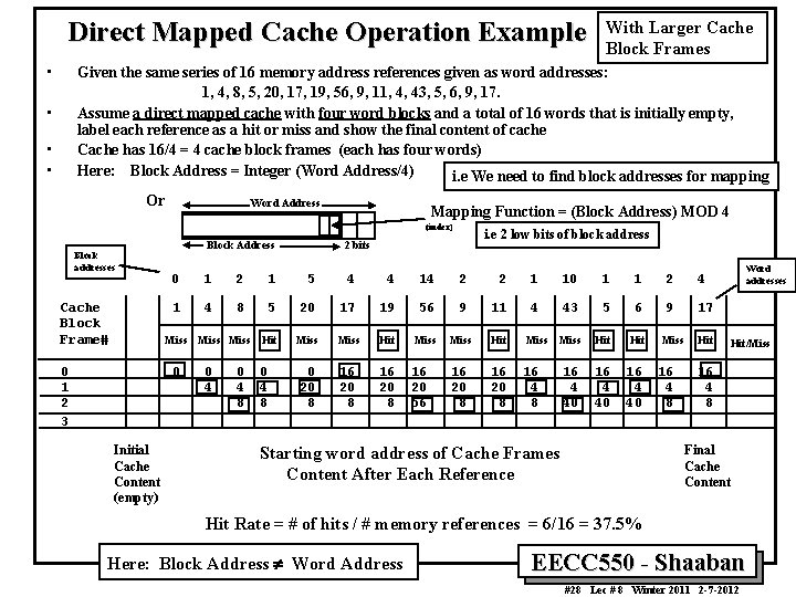
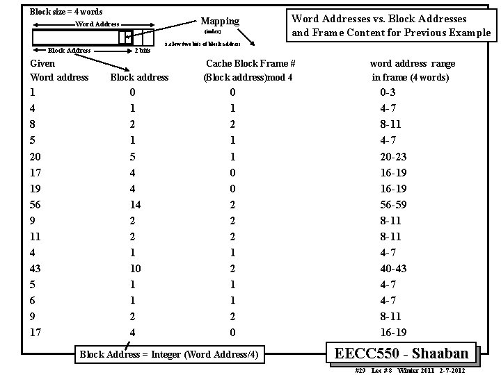
Direct Mapped Cache Operation Example • With Larger Cache Block Frames Given the same series of 16 memory address references given as word addresses: 1, 4, 8, 5, 20, 17, 19, 56, 9, 11, 4, 43, 5, 6, 9, 17. Assume a direct mapped cache with four word blocks and a total of 16 words that is initially empty, label each reference as a hit or miss and show the final content of cache Cache has 16/4 = 4 cache block frames (each has four words) Here: Block Address = Integer (Word Address/4) i. e We need to find block addresses for mapping • • • Or Word Address Mapping Function = (Block Address) MOD 4 (index) Block addresses Cache Block Frame# Block Address 0 1 2 1 5 4 4 14 2 2 1 10 1 1 2 4 1 4 8 5 20 17 19 56 9 11 4 43 5 6 9 17 Hit Miss Hit Miss Hit 0 4 8 0 20 8 16 20 56 16 20 8 16 4 40 Miss 0 1 2 3 0 Initial Cache Content (empty) i. e 2 low bits of block address 2 bits Miss 0 4 8 16 4 8 Word addresses Hit/Miss 16 4 8 Final Cache Content Starting word address of Cache Frames Content After Each Reference Hit Rate = # of hits / # memory references = 6/16 = 37. 5% Here: Block Address ¹ Word Address EECC 550 - Shaaban #28 Lec # 8 Winter 2011 2 -7 -2012
Block size = 4 words Mapping Word Address (index) Block Address Given Word address 1 4 8 5 20 17 19 56 9 11 4 43 5 6 9 17 2 bits i. e low two bits of block address Block address 0 1 2 1 5 4 4 14 2 2 1 10 1 1 2 4 Word Addresses vs. Block Addresses and Frame Content for Previous Example Cache Block Frame # (Block address)mod 4 0 1 2 1 1 0 0 2 2 2 1 1 2 0 Block Address = Integer (Word Address/4) word address range in frame (4 words) 0 -3 4 -7 8 -11 4 -7 20 -23 16 -19 56 -59 8 -11 4 -7 40 -43 4 -7 8 -11 16 -19 EECC 550 - Shaaban #29 Lec # 8 Winter 2011 2 -7 -2012
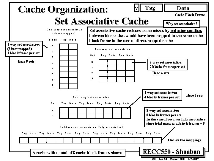
Tag V Cache Organization: Set Associative Cache (d ire c t m a p p e d ) 1 -way set associative: (direct mapped) 1 block frame per set T ag D a ta Why set associative? 0 T w o - w a y s e t a s s o c i a t iv e 1 Set 2 Here 8 sets Cache Block Frame Set associative cache reduces cache misses by reducing conflicts between blocks that would have been mapped to the same cache block frame in the case of direct mapped cache O n e - w a y s e t a s s o c i a t iv e B lo c k Data Tag D a ta 2 -way set associative: 2 blocks frames per set 0 3 1 4 Here 4 sets 2 5 3 6 7 4 -way set associative: 4 blocks frames per set F o u r - w a y s e t a s s o c ia tiv e S et T ag D a ta Tag Here 2 sets D a ta 0 8 -way set associative: 8 blocks frames per set In this case it becomes fully associative since total number of block frames = 8 1 E ig h t - w a y s e t a s s o c ia t iv e ( fu l ly a s s o c i a t i v e ) Tag D a ta Tag D a ta One set (no mapping) A cache with a total of 8 cache block frames shown EECC 550 - Shaaban #30 Lec # 8 Winter 2011 2 -7 -2012
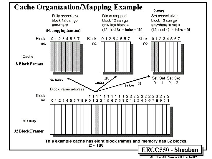
Cache Organization/Mapping Example = index = 100 (No mapping function) 2 -way = index = 00 8 Block Frames No Index 100 Index 00 32 Block Frames 12 = 1100 EECC 550 - Shaaban #31 Lec # 8 Winter 2011 2 -7 -2012
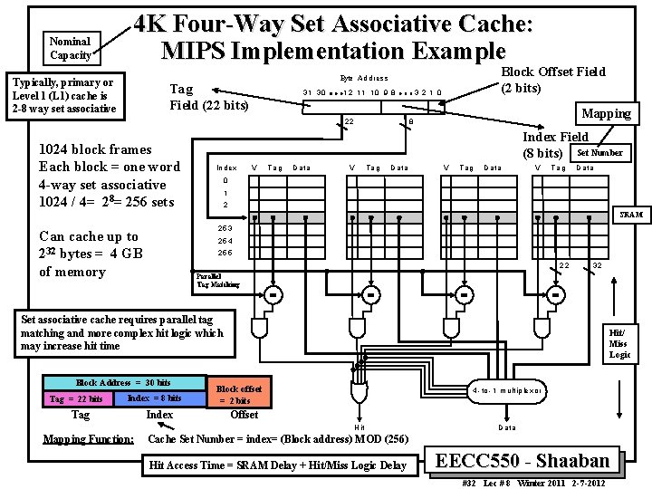
Nominal Capacity 4 K Four-Way Set Associative Cache: MIPS Implementation Example Typically, primary or Level 1 (L 1) cache is 2 -8 way set associative Tag Field (22 bits) 31 3 0 12 11 10 9 8 3 2 1 0 Mapping 8 22 1024 block frames Each block = one word 4 -way set associative 1024 / 4= 28= 256 sets Block Offset Field (2 bits) Byte A d dre s s Index Field (8 bits) Set Number In d ex V Tag D a ta V T ag D ata V T ag D a ta 0 1 2 SRAM 253 Can cache up to 232 bytes = 4 GB of memory 254 255 22 32 Parallel Tag Matching Set associative cache requires parallel tag matching and more complex hit logic which may increase hit time Block Address = 30 bits Tag = 22 bits Index = 8 bits Tag Index Hit/ Miss Logic Block offset = 2 bits 4 - to - 1 m u ltip le xo r Offset H it Mapping Function: D a ta Cache Set Number = index= (Block address) MOD (256) Hit Access Time = SRAM Delay + Hit/Miss Logic Delay EECC 550 - Shaaban #32 Lec # 8 Winter 2011 2 -7 -2012
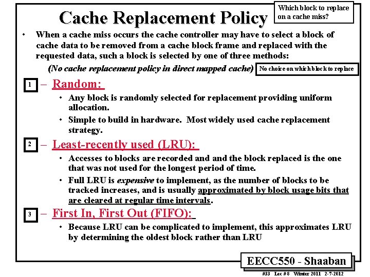
Cache Replacement Policy • Which block to replace on a cache miss? When a cache miss occurs the cache controller may have to select a block of cache data to be removed from a cache block frame and replaced with the requested data, such a block is selected by one of three methods: (No cache replacement policy in direct mapped cache) No choice on which block to replace 1 – Random: • Any block is randomly selected for replacement providing uniform allocation. • Simple to build in hardware. Most widely used cache replacement strategy. 2 – Least-recently used (LRU): • Accesses to blocks are recorded and the block replaced is the one that was not used for the longest period of time. • Full LRU is expensive to implement, as the number of blocks to be tracked increases, and is usually approximated by block usage bits that are cleared at regular time intervals. 3 – First In, First Out (FIFO): • Because LRU can be complicated to implement, this approximates LRU by determining the oldest block rather than LRU EECC 550 - Shaaban #33 Lec # 8 Winter 2011 2 -7 -2012
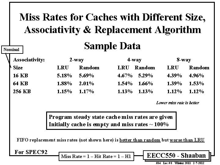
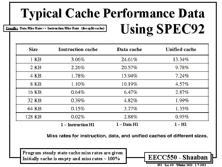
Miss Rates for Caches with Different Size, Associativity & Replacement Algorithm Nominal Associativity: Size 16 KB 64 KB 256 KB Sample Data 2 -way LRU Random 5. 18% 5. 69% 1. 88% 2. 01% 1. 15% 1. 17% 4 -way LRU Random 4. 67% 5. 29% 1. 54% 1. 66% 1. 13% 8 -way LRU Random 4. 39% 4. 96% 1. 39% 1. 53% 1. 12% Lower miss rate is better Program steady state cache miss rates are given Initially cache is empty and miss rates ~ 100% FIFO replacement miss rates (not shown here) is better than random but worse than LRU For SPEC 92 Miss Rate = 1 – Hit Rate = 1 – H 1 EECC 550 - Shaaban #34 Lec # 8 Winter 2011 2 -7 -2012
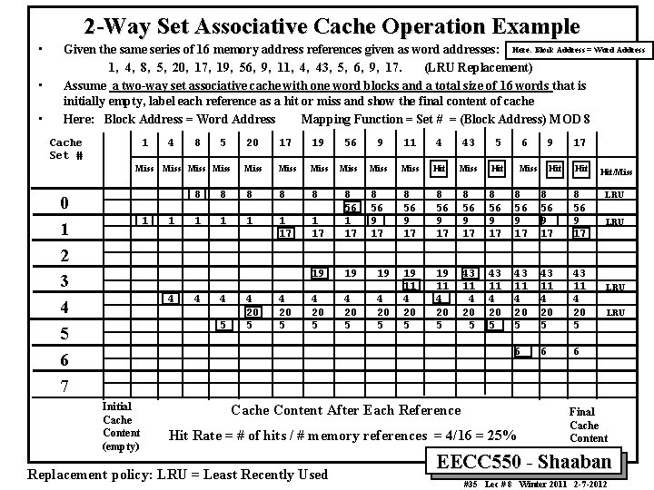
2 -Way Set Associative Cache Operation Example • • • Given the same series of 16 memory address references given as word addresses: Here: Block Address = Word Address 1, 4, 8, 5, 20, 17, 19, 56, 9, 11, 4, 43, 5, 6, 9, 17. (LRU Replacement) Assume a two-way set associative cache with one word blocks and a total size of 16 words that is initially empty, label each reference as a hit or miss and show the final content of cache Here: Block Address = Word Address Mapping Function = Set # = (Block Address) MOD 8 Cache Set # 1 Miss 0 1 2 3 4 5 6 7 1 4 8 5 Miss 1 4 17 19 56 9 11 4 43 5 Miss Miss Hit 8 56 9 17 8 56 9 17 19 11 4 20 5 43 11 4 20 5 8 8 8 1 1 17 8 56 1 17 19 19 4 4 5 Initial Cache Content (empty) 20 4 20 5 19 4 20 5 6 9 17 Miss Hit Hit/Miss 8 56 9 17 LRU 43 11 4 20 5 6 6 6 Cache Content After Each Reference Hit Rate = # of hits / # memory references = 4/16 = 25% Replacement policy: LRU = Least Recently Used LRU LRU Final Cache Content EECC 550 - Shaaban #35 Lec # 8 Winter 2011 2 -7 -2012
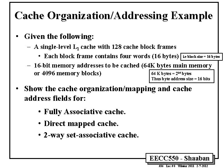
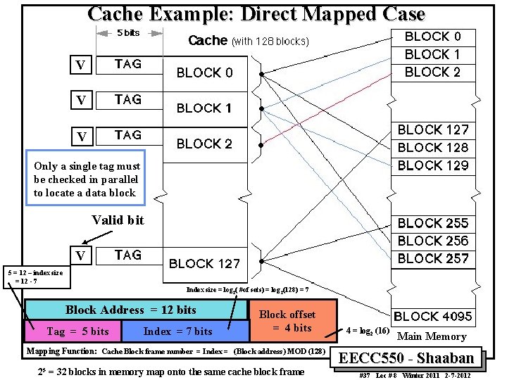
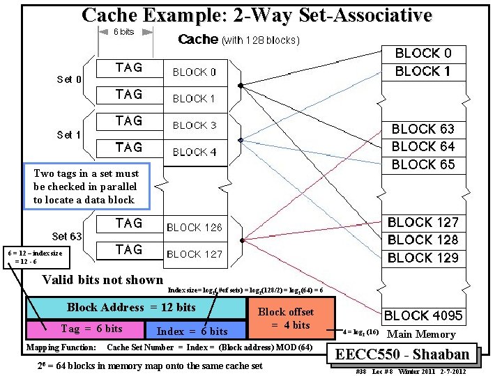
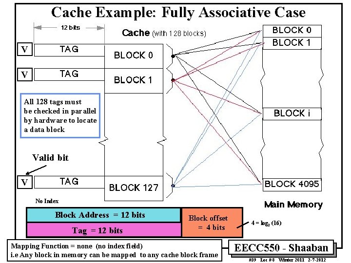
Cache Organization/Addressing Example • Given the following: – A single-level L 1 cache with 128 cache block frames • Each block frame contains four words (16 bytes) i. e block size = 16 bytes – 16 -bit memory addresses to be cached (64 K bytes main memory 64 K bytes = 216 bytes or 4096 memory blocks) Thus byte address size = 16 bits • Show the cache organization/mapping and cache address fields for: • Fully Associative cache. • Direct mapped cache. • 2 -way set-associative cache. EECC 550 - Shaaban #36 Lec # 8 Winter 2011 2 -7 -2012
Cache Example: Direct Mapped Case V V V Only a single tag must be checked in parallel to locate a data block Valid bit V 5 = 12 – index size = 12 - 7 Index size = log 2( #of sets) = log 2(128) = 7 Block Address = 12 bits Tag = 5 bits Index = 7 bits Block offset = 4 bits Mapping Function: Cache Block frame number = Index = (Block address) MOD (128) 25 = 32 blocks in memory map onto the same cache block frame 4 = log 2 (16) Main Memory EECC 550 - Shaaban #37 Lec # 8 Winter 2011 2 -7 -2012
Cache Example: 2 -Way Set-Associative Two tags in a set must be checked in parallel to locate a data block 6 = 12 – index size = 12 - 6 Valid bits not shown Index size= log 2( #of sets) = log 2(128/2) = log 2(64) = 6 Block Address = 12 bits Tag = 6 bits Mapping Function: 26 Index = 6 bits Block offset = 4 bits Cache Set Number = Index = (Block address) MOD (64) = 64 blocks in memory map onto the same cache set 4 = log 2 (16) Main Memory EECC 550 - Shaaban #38 Lec # 8 Winter 2011 2 -7 -2012
Cache Example: Fully Associative Case V V All 128 tags must be checked in parallel by hardware to locate a data block Valid bit V No Index Block Address = 12 bits Tag = 12 bits Block offset = 4 bits Mapping Function = none (no index field) i. e Any block in memory can be mapped to any cache block frame 4 = log 2 (16) EECC 550 - Shaaban #39 Lec # 8 Winter 2011 2 -7 -2012
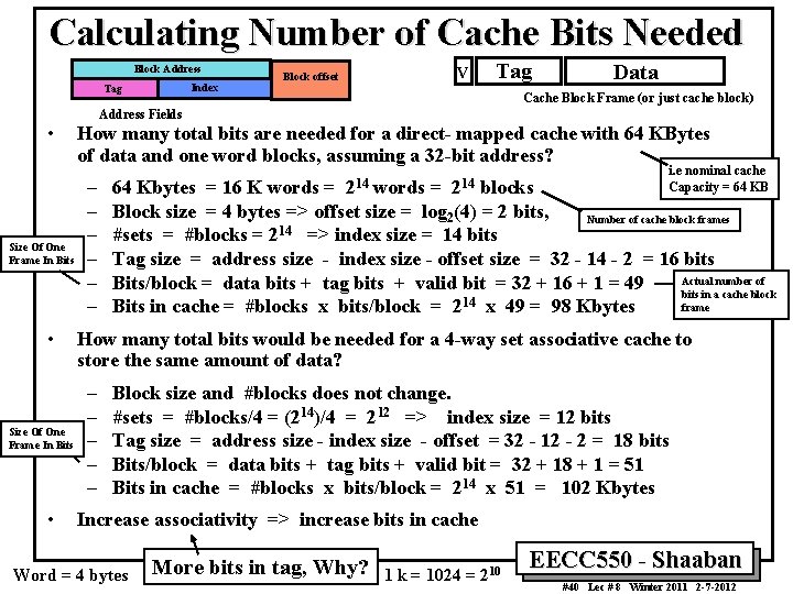
Calculating Number of Cache Bits Needed Block Address Index Tag V Block offset Tag Data Cache Block Frame (or just cache block) Address Fields • Size Of One Frame In Bits • How many total bits are needed for a direct- mapped cache with 64 KBytes of data and one word blocks, assuming a 32 -bit address? – – – 214 i. e nominal cache Capacity = 64 KB 64 Kbytes = 16 K words = blocks Block size = 4 bytes => offset size = log 2(4) = 2 bits, Number of cache block frames 14 #sets = #blocks = 2 => index size = 14 bits Tag size = address size - index size - offset size = 32 - 14 - 2 = 16 bits Actual number of Bits/block = data bits + tag bits + valid bit = 32 + 16 + 1 = 49 bits in a cache block 14 frame Bits in cache = #blocks x bits/block = 2 x 49 = 98 Kbytes How many total bits would be needed for a 4 -way set associative cache to store the same amount of data? – – – Block size and #blocks does not change. #sets = #blocks/4 = (214)/4 = 212 => index size = 12 bits Tag size = address size - index size - offset = 32 - 12 - 2 = 18 bits Bits/block = data bits + tag bits + valid bit = 32 + 18 + 1 = 51 Bits in cache = #blocks x bits/block = 214 x 51 = 102 Kbytes Increase associativity => increase bits in cache Word = 4 bytes More bits in tag, Why? 1 k = 1024 = 210 EECC 550 - Shaaban #40 Lec # 8 Winter 2011 2 -7 -2012
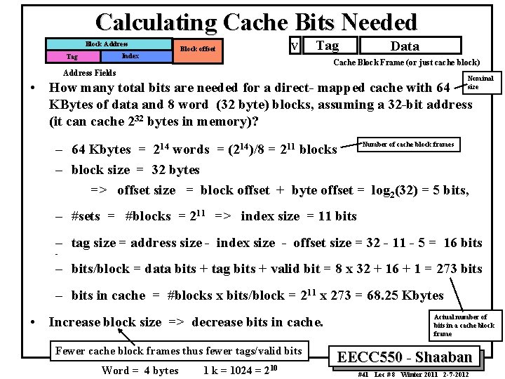
Calculating Cache Bits Needed Block Address Index Tag V Block offset Tag Data Cache Block Frame (or just cache block) Address Fields Nominal size • How many total bits are needed for a direct- mapped cache with 64 KBytes of data and 8 word (32 byte) blocks, assuming a 32 -bit address (it can cache 232 bytes in memory)? Number of cache block frames – 64 Kbytes = 214 words = (214)/8 = 211 blocks – block size = 32 bytes => offset size = block offset + byte offset = log 2(32) = 5 bits, – #sets = #blocks = 211 => index size = 11 bits – tag size = address size - index size - offset size = 32 - 11 - 5 = 16 bits – – bits/block = data bits + tag bits + valid bit = 8 x 32 + 16 + 1 = 273 bits – bits in cache = #blocks x bits/block = 211 x 273 = 68. 25 Kbytes • Increase block size => decrease bits in cache. Fewer cache block frames thus fewer tags/valid bits Word = 4 bytes 1 k = 1024 = 210 Actual number of bits in a cache block frame EECC 550 - Shaaban #41 Lec # 8 Winter 2011 2 -7 -2012
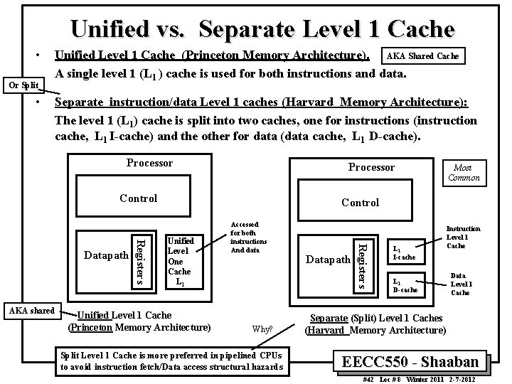
Unified vs. Separate Level 1 Cache • Or Split • Unified Level 1 Cache (Princeton Memory Architecture). AKA Shared Cache A single level 1 (L 1 ) cache is used for both instructions and data. Separate instruction/data Level 1 caches (Harvard Memory Architecture): The level 1 (L 1) cache is split into two caches, one for instructions (instruction cache, L 1 I-cache) and the other for data (data cache, L 1 D-cache). Processor Control Unified Level One Cache L 1 Unified Level 1 Cache (Princeton Memory Architecture) Accessed for both instructions And data Why? Split Level 1 Cache is more preferred in pipelined CPUs to avoid instruction fetch/Data access structural hazards Datapath Registers AKA shared Registers Datapath Most Common L 1 I-cache L 1 D-cache Instruction Level 1 Cache Data Level 1 Cache Separate (Split) Level 1 Caches (Harvard Memory Architecture) EECC 550 - Shaaban #42 Lec # 8 Winter 2011 2 -7 -2012
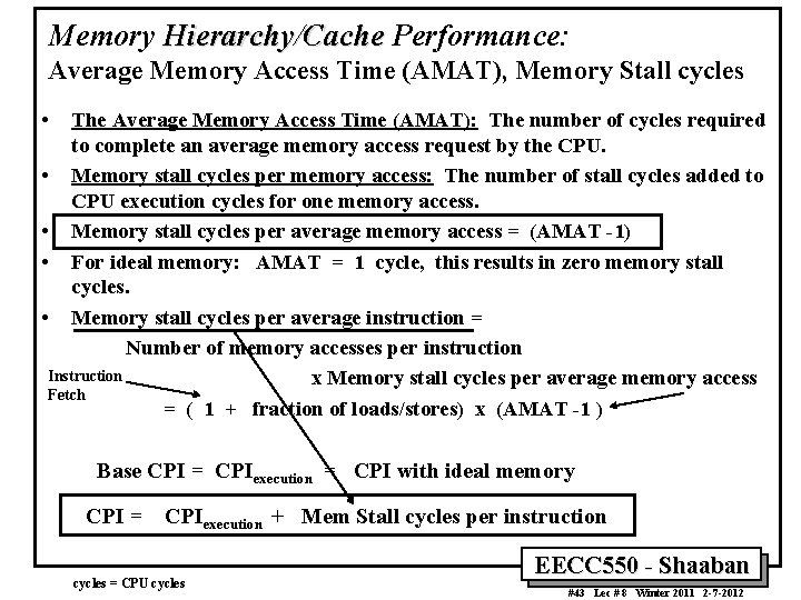
Memory Hierarchy/Cache Performance: Average Memory Access Time (AMAT), Memory Stall cycles • The Average Memory Access Time (AMAT): The number of cycles required to complete an average memory access request by the CPU. • Memory stall cycles per memory access: The number of stall cycles added to CPU execution cycles for one memory access. • Memory stall cycles per average memory access = (AMAT -1) • For ideal memory: AMAT = 1 cycle, this results in zero memory stall cycles. • Memory stall cycles per average instruction = Number of memory accesses per instruction Instruction x Memory stall cycles per average memory access Fetch = ( 1 + fraction of loads/stores) x (AMAT -1 ) Base CPI = CPIexecution = CPI with ideal memory CPI = CPIexecution + Mem Stall cycles per instruction cycles = CPU cycles EECC 550 - Shaaban #43 Lec # 8 Winter 2011 2 -7 -2012
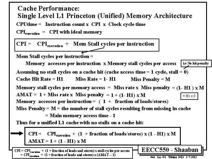
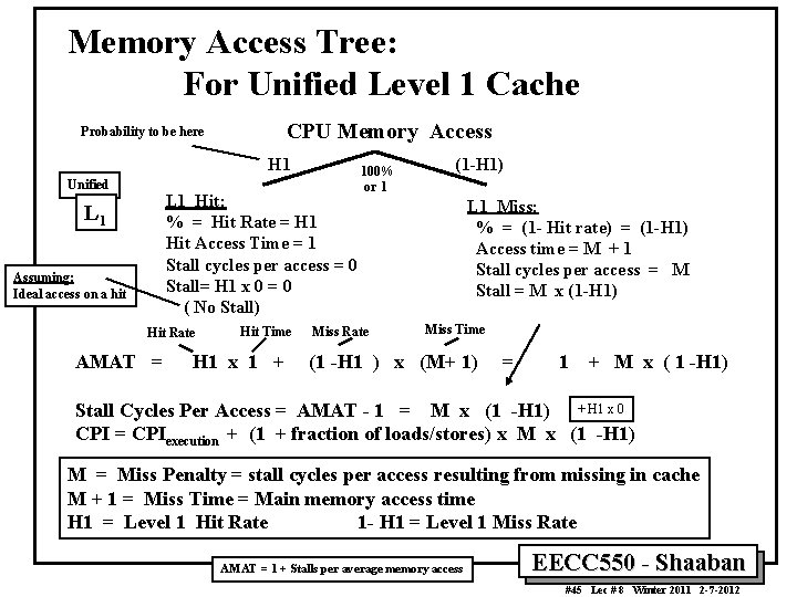
Cache Performance: Single Level L 1 Princeton (Unified) Memory Architecture CPUtime = Instruction count x CPI x Clock cycle time CPIexecution = CPI with ideal memory CPI = CPIexecution + Mem Stall cycles per instruction = Memory accesses per instruction x Memory stall cycles per access i. e No hit penalty Assuming no stall cycles on a cache hit (cache access time = 1 cycle, stall = 0) Cache Hit Rate = H 1 Miss Rate = 1 - H 1 Miss Penalty = M Memory stall cycles per memory access = Miss rate x Miss penalty = (1 - H 1 ) x M AMAT = 1 + Miss rate x Miss penalty = 1 + (1 - H 1) x M + H 1 x 0 Memory accesses per instruction = ( 1 + fraction of loads/stores) Miss Penalty = M = the number of stall cycles resulting from missing in cache = Main memory access time - 1 Thus for a unified L 1 cache with no stalls on a cache hit: CPI = CPIexecution + (1 + fraction of loads/stores) x (1 - H 1) x M AMAT = 1 + (1 - H 1) x M CPI = CPIexecution + (1 + fraction of loads and stores) x stall cycles per access = CPIexecution + (1 + fraction of loads and stores) x (AMAT – 1) EECC 550 - Shaaban #44 Lec # 8 Winter 2011 2 -7 -2012
Memory Access Tree: For Unified Level 1 Cache CPU Memory Access Probability to be here H 1 Unified L 1 Hit: % = Hit Rate = H 1 Hit Access Time = 1 Stall cycles per access = 0 Stall= H 1 x 0 = 0 ( No Stall) L 1 Assuming: Ideal access on a hit Hit Rate AMAT = Hit Time H 1 x 1 + 100% or 1 Miss Rate (1 -H 1) L 1 Miss: % = (1 - Hit rate) = (1 -H 1) Access time = M + 1 Stall cycles per access = M Stall = M x (1 -H 1) Miss Time (1 -H 1 ) x (M+ 1) = 1 + M x ( 1 -H 1) Stall Cycles Per Access = AMAT - 1 = M x (1 -H 1) + H 1 x 0 CPI = CPIexecution + (1 + fraction of loads/stores) x M x (1 -H 1) M = Miss Penalty = stall cycles per access resulting from missing in cache M + 1 = Miss Time = Main memory access time H 1 = Level 1 Hit Rate 1 - H 1 = Level 1 Miss Rate AMAT = 1 + Stalls per average memory access EECC 550 - Shaaban #45 Lec # 8 Winter 2011 2 -7 -2012
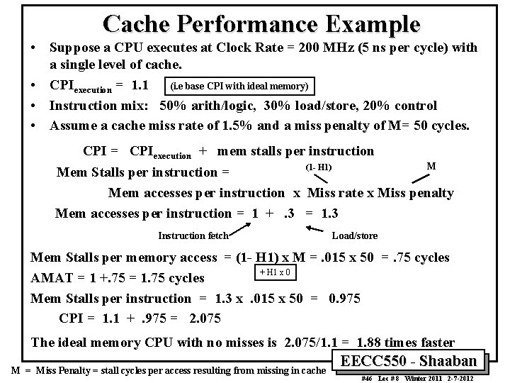
Cache Performance Example • Suppose a CPU executes at Clock Rate = 200 MHz (5 ns per cycle) with a single level of cache. • CPIexecution = 1. 1 (i. e base CPI with ideal memory) • Instruction mix: 50% arith/logic, 30% load/store, 20% control • Assume a cache miss rate of 1. 5% and a miss penalty of M= 50 cycles. CPI = CPIexecution + mem stalls per instruction M (1 - H 1) Mem Stalls per instruction = Mem accesses per instruction x Miss rate x Miss penalty Mem accesses per instruction = 1 +. 3 = 1. 3 Instruction fetch Load/store Mem Stalls per memory access = (1 - H 1) x M =. 015 x 50 =. 75 cycles + H 1 x 0 AMAT = 1 +. 75 = 1. 75 cycles Mem Stalls per instruction = 1. 3 x. 015 x 50 = 0. 975 CPI = 1. 1 +. 975 = 2. 075 The ideal memory CPU with no misses is 2. 075/1. 1 = 1. 88 times faster M = Miss Penalty = stall cycles per access resulting from missing in cache EECC 550 - Shaaban #46 Lec # 8 Winter 2011 2 -7 -2012
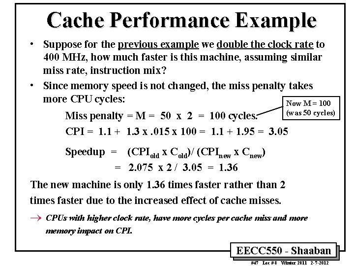
Cache Performance Example • Suppose for the previous example we double the clock rate to 400 MHz, how much faster is this machine, assuming similar miss rate, instruction mix? • Since memory speed is not changed, the miss penalty takes more CPU cycles: Now M = 100 (was 50 cycles) Miss penalty = M = 50 x 2 = 100 cycles. CPI = 1. 1 + 1. 3 x. 015 x 100 = 1. 1 + 1. 95 = 3. 05 Speedup = (CPIold x Cold)/ (CPInew x Cnew) = 2. 075 x 2 / 3. 05 = 1. 36 The new machine is only 1. 36 times faster rather than 2 times faster due to the increased effect of cache misses. ® CPUs with higher clock rate, have more cycles per cache miss and more memory impact on CPI. EECC 550 - Shaaban #47 Lec # 8 Winter 2011 2 -7 -2012
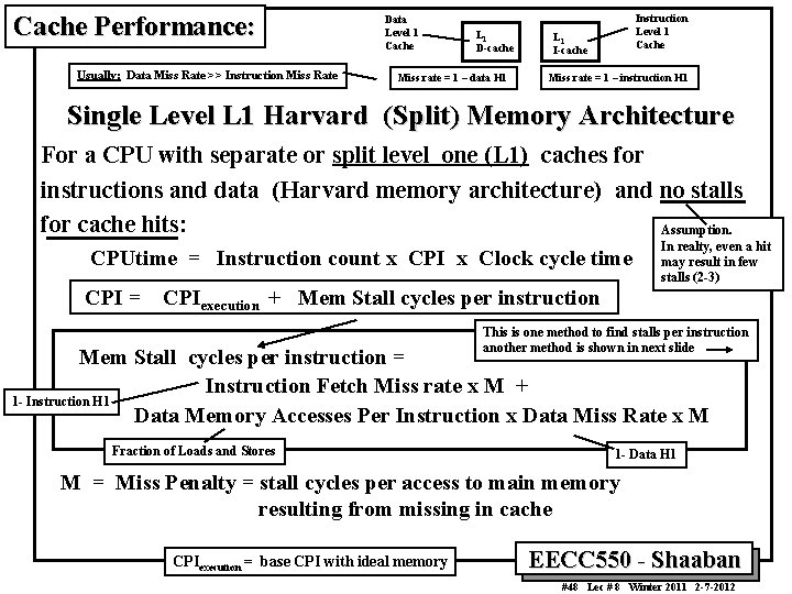
Cache Performance: Usually: Data Miss Rate >> Instruction Miss Rate Data Level 1 Cache L 1 D-cache Miss rate = 1 – data H 1 Instruction Level 1 Cache L 1 I-cache Miss rate = 1 – instruction H 1 Single Level L 1 Harvard (Split) Memory Architecture For a CPU with separate or split level one (L 1) caches for instructions and data (Harvard memory architecture) and no stalls for cache hits: Assumption. CPUtime = Instruction count x CPI x Clock cycle time CPI = CPIexecution + Mem Stall cycles per instruction In realty, even a hit may result in few stalls (2 -3) This is one method to find stalls per instruction another method is shown in next slide Mem Stall cycles per instruction = Instruction Fetch Miss rate x M + 1 - Instruction H 1 Data Memory Accesses Per Instruction x Data Miss Rate x M Fraction of Loads and Stores 1 - Data H 1 M = Miss Penalty = stall cycles per access to main memory resulting from missing in cache CPIexecution = base CPI with ideal memory EECC 550 - Shaaban #48 Lec # 8 Winter 2011 2 -7 -2012
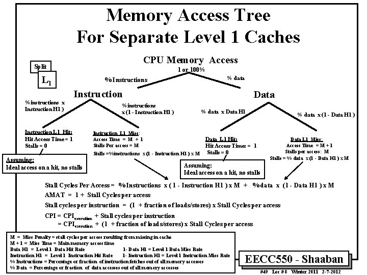
Memory Access Tree For Separate Level 1 Caches CPU Memory Access Split 1 or 100% L 1 % data % Instructions Instruction %instructions x Instruction H 1 ) Instruction L 1 Hit: Hit Access Time = 1 Stalls = 0 Data %instructions x (1 - Instruction H 1 ) % data x Data H 1 Instruction L 1 Miss: Access Time = M + 1 Stalls Per access = M Stalls =%instructions x (1 - Instruction H 1 ) x M Assuming: Ideal access on a hit, no stalls Data L 1 Hit: Hit Access Time: = 1 Stalls = 0 % data x (1 - Data H 1 ) Data L 1 Miss: Access Time = M + 1 Stalls per access: M Stalls = % data x (1 - Data H 1 ) x M Assuming: Ideal access on a hit, no stalls Stall Cycles Per Access = % Instructions x ( 1 - Instruction H 1 ) x M + % data x (1 - Data H 1 ) x M AMAT = 1 + Stall Cycles per access Stall cycles per instruction = (1 + fraction of loads/stores) x Stall Cycles per access CPI = CPIexecution + Stall cycles per instruction = CPIexecution + (1 + fraction of loads/stores) x Stall Cycles per access M = Miss Penalty = stall cycles per access resulting from missing in cache M + 1 = Miss Time = Main memory access time Data H 1 = Level 1 Data Hit Rate 1 - Data H 1 = Level 1 Data Miss Rate Instruction H 1 = Level 1 Instruction Hit Rate 1 - Instruction H 1 = Level 1 Instruction Miss Rate % Instructions = Percentage or fraction of instruction fetches out of all memory accesses % Data = Percentage or fraction of data accesses out of all memory accesses EECC 550 - Shaaban #49 Lec # 8 Winter 2011 2 -7 -2012
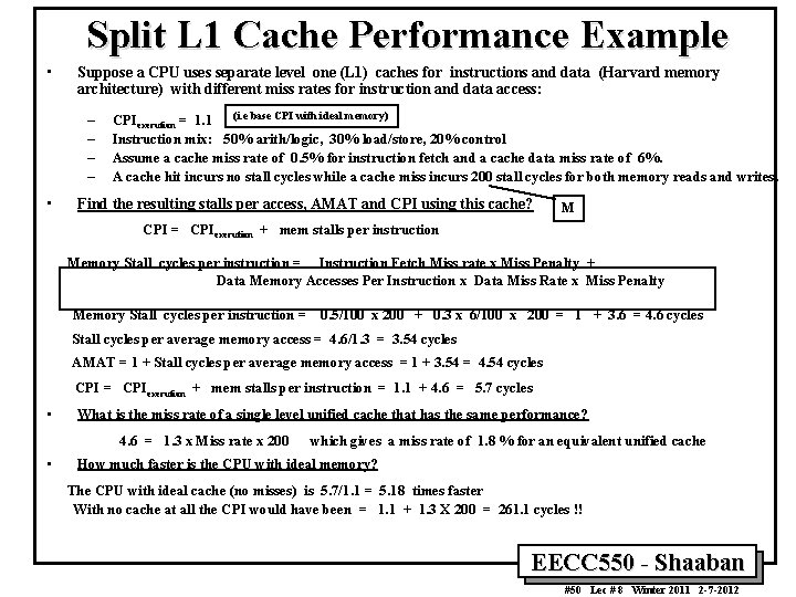
Split L 1 Cache Performance Example • Suppose a CPU uses separate level one (L 1) caches for instructions and data (Harvard memory architecture) with different miss rates for instruction and data access: – – • CPIexecution = 1. 1 (i. e base CPI with ideal memory) Instruction mix: 50% arith/logic, 30% load/store, 20% control Assume a cache miss rate of 0. 5% for instruction fetch and a cache data miss rate of 6%. A cache hit incurs no stall cycles while a cache miss incurs 200 stall cycles for both memory reads and writes. Find the resulting stalls per access, AMAT and CPI using this cache? M CPI = CPIexecution + mem stalls per instruction Memory Stall cycles per instruction = Instruction Fetch Miss rate x Miss Penalty + Data Memory Accesses Per Instruction x Data Miss Rate x Miss Penalty Memory Stall cycles per instruction = 0. 5/100 x 200 + 0. 3 x 6/100 x 200 = 1 + 3. 6 = 4. 6 cycles Stall cycles per average memory access = 4. 6/1. 3 = 3. 54 cycles AMAT = 1 + Stall cycles per average memory access = 1 + 3. 54 = 4. 54 cycles CPI = CPIexecution + mem stalls per instruction = 1. 1 + 4. 6 = 5. 7 cycles • What is the miss rate of a single level unified cache that has the same performance? 4. 6 = 1. 3 x Miss rate x 200 • which gives a miss rate of 1. 8 % for an equivalent unified cache How much faster is the CPU with ideal memory? The CPU with ideal cache (no misses) is 5. 7/1. 1 = 5. 18 times faster With no cache at all the CPI would have been = 1. 1 + 1. 3 X 200 = 261. 1 cycles !! EECC 550 - Shaaban #50 Lec # 8 Winter 2011 2 -7 -2012
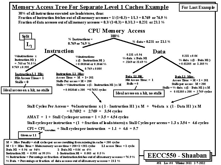
Memory Access Tree For Separate Level 1 Caches Example For Last Example 30% of all instructions executed are loads/stores, thus: Fraction of instruction fetches out of all memory accesses = 1/ (1+0. 3) = 1/1. 3 = 0. 769 or 76. 9 % Fraction of data accesses out of all memory accesses = 0. 3/ (1+0. 3) = 0. 3/1. 3 = 0. 231 or 23. 1 % CPU Memory Access Split L 1 % Instructions = 0. 769 or 76. 9 % 100% % data = 0. 231 or 23. 1 % Instruction %instructions x Instruction H 1 ) =. 765 or 76. 5 % 0. 769 x 0. 995 Instruction L 1 Hit: Hit Access Time = 1 Stalls = 0 Ideal access on a hit, no stalls 0. 231 x 0. 94 % data x Data H 1 =. 2169 or 21. 69 % %instructions x (1 - Instruction H 1 ) = 0. 003846 or 0. 3846 % 0. 769 x 0. 005 Instruction L 1 Miss: Access Time = M + 1= 201 Stalls Per access = M = 200 Stalls = %instructions x (1 - Instruction H 1 ) x M = 0. 003846 x 200 =0. 7692 cycles Data L 1 Hit: Hit Access Time: = 1 Stalls = 0 Ideal access on a hit, no stalls 0. 231 x 0. 06 % data x (1 - Data H 1 ) = 0. 01385 or 1. 385 % Data L 1 Miss: Access Time = M + 1 = 201 Stalls per access: M = 200 Stalls = % data x (1 - Data H 1 ) x M = 0. 01385 x 200 = 2. 769 cycles Stall Cycles Per Access = % Instructions x ( 1 - Instruction H 1 ) x M + % data x (1 - Data H 1 ) x M = 0. 7692 + 2. 769 = 3. 54 cycles AMAT = 1 + Stall Cycles per access = 1 + 3. 5 = 4. 54 cycles Stall cycles per instruction = (1 + fraction of loads/stores) x Stall Cycles per access = 1. 3 x 3. 54 = 4. 6 cycles CPI = CPIexecution + Stall cycles per instruction = 1. 1 + 4. 6 = 5. 7 Given as 1. 1 M = Miss Penalty = stall cycles per access resulting from missing in cache = 200 cycles M + 1 = Miss Time = Main memory access time = 200+1 =201 cycles L 1 access Time = 1 cycle Data H 1 = 0. 94 or 94% 1 - Data H 1 = 0. 06 or 6% Instruction H 1 = 0. 995 or 99. 5% 1 - Instruction H 1 = 0. 005 or 0. 5 % % Instructions = Percentage or fraction of instruction fetches out of all memory accesses = 76. 9 % % Data = Percentage or fraction of data accesses out of all memory accesses = 23. 1 % EECC 550 - Shaaban #51 Lec # 8 Winter 2011 2 -7 -2012
Typical Cache Performance Data Using SPEC 92 Usually: Data Miss Rate >> Instruction Miss Rate (for split cache) 1 – Instruction H 1 1 – Data H 1 Program steady state cache miss rates are given Initially cache is empty and miss rates ~ 100% 1 – H 1 EECC 550 - Shaaban #52 Lec # 8 Winter 2011 2 -7 -2012