Project by Sabri UZUNER LEARNNG OBJECTVES What is

Project by. Sabri UZUNER

LEARNİNG OBJECTİVES • • What is robotics History of robot Laws of robotics Advantages and Disadvantage

What is a Robot?

• “A reprogrammable, multifunctional manipulator designed to move material, parts, tools, or specialized devices through various programmed motions for the performance of a variety of tasks. ” (Robot Institute of America, 1979) • “Force through intelligence. ” • “Where Artificial Intelligence meet the real world. ” • “An automatic device that performs functions normally ascribed to humans or a machine in the form of a human. ”

1. The Early Stages 2. Our Time 3. Future

“Automatic Scribe”. 1774 by Pierre & Henri-Louis Jasquet-Droz “Talking “Teleautomation”, 1899, Doll”. 1890, Nikola Tesla Edison Textile Machine (19 th. Thomas century) Karel 1921 1940, WEC, “Electra Isaak Capek, Asimov, 1941 and Sparco”

Our Time -Industry -Military -Research -Space

Industry

Military robotics

Research and space robots

The Future • Nanotechnology • Telesurgery

Nanorobot

Telesurgery

Asimov’s Laws of Robotics: 1. A Robot may not injure a human being or through inaction, allow a human being to come to harm; 2. A Robot must obey orders given it by human beings except where such orders would conflict with the first law; 3. A Robot must protect its own existence as larges such protection does not conflict with the first or second law;

Advantages and disadvantages

Advantages

Disadvantages

Introduction of System Robotic Arm Control Panel Power Supply

Design Steps of Robotic Arm Design of Mechanic Selection of Motor Selection of Metarial Design of Electronic Design of Software Control Panel Manual Control Power Supply Forward Kinematic Invers Kinematic Trajectory Analysis Simulation

Economical Feasibility 5 DOF ROBOTIC ARM End Effector Roll Pitch elbow Shoulder Base SERVO DIVER SERVO CABLE USB CABLE Robotic Arm Power Supply Type of Metarial SM-S 3217 M Servo Motor N 580 Servo Motor SM-S 4481 M Servo Motor 5030 DX Servo Motor XQ-S 5040 D Servo Motor SM-S 8166 M Servo Motor Micro Maestro 6 -Channel USB Servo Controller (Assembled) Unit Price/Unit($) 1 15 1 24 1 45 1 28 1 35 1 43 TOTAL 15 24 45 28 35 43 1 18 18 48 inch Standard Extension(Futaba) 2 5 10 48 inch Standard Extension(Hitec) USB Cable A to Mini-B 6 ft. Mecanic (roller, screw etc. ) Elektronic (Resistor, IC, etc) 4 1 6 2 145 60 TOTAL Price of Part in Robotic Arm 24 2 145 60 483$

Mechanic

Base Bottom and Top Flat Surface Connect to Servo Motor Roller Balancing Moving Flat Surface Servo Motor

Shoulder-Elbow-Wrist-End Effector:

Axis End Effector Angle of Rotation 0 -330 mm Pitch 47, 32° to -47, 64° Roll 86, 75° to -83, 34° Base 107, 26°to -102, 8° Elbow 95, 07° to -84, 36° Shoulder 146, 831° to -3, 19° Rotation Angle of Robotic Arm

Electronic Power Supply Micro Maestro 6 -Channel USB Servo Controlor

0 -36 V 10 A Regulated Circuit Diagram of Regulated Circuit

0 -36 V 10 A Regülated Circuit ARES 3 D

Micro Maestro 6 -Channel USB Servo Controller

Dimensions of Micro Maestro 6 -Channel USB Servo Control

Which Motor is suitable ? DC Motor AC Motor Servo Motor Step Motor
 Servo Parts of RC Servo")
RC (Radio Control) Servo Parts of RC Servo

Architecture Cable of RC servo

RC Servo Applications

Control of Servo with PWM

Calculate of Torque RC Servos ØLagrange-Euler ØRekürsif Lagrange-Euler ØNewton-Euler Ød’Alembert Methods

Axis of Robot Locations Center of Gravity

Axis Gripper Torque 4. 3 kg/cm pitch 5 kg/cm Roll 12. 8 kg/cm Elbow Shoulder Base 30 kg/cm 39. 8 kg/cm 30 kg/cm Torque of Each Motor

Kinematics Analysis Ø Forward Kinematics Ø Inverse Kinematics Ø Trajectory Analysis

Forward Kinematic

Methods of Forward Kinematics • Denavit-Hartenberg Method • Exponential Method • Pieper-Roth Yöntemi

Denavit-Hartenberg Method Z 3 Y 3 Z 2 X 3 X 0 Q 2 X 2 H 2 y 1 X 0 L 4 Z 1 X 9 Z 9 X 5 Y 4 L 3 Z 6 Y 5 Z 0 Q 4 L 2 Z 5 X 4 Y 0 Y 8 Q 3 Z 4 H 1 Z 8 Y 7 L 1 Q 1 X 7 Z 7 Y 2 X 8 X 6 Y 6 Q 5 Y 9
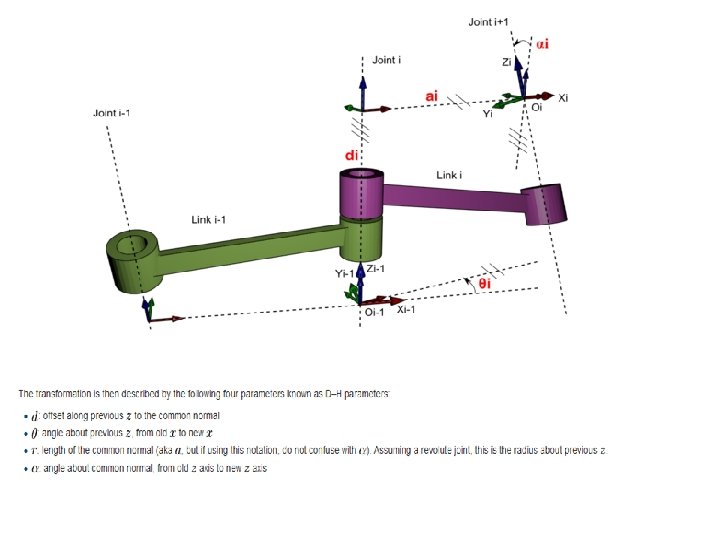

D-H Parameters α i-1 ai-1 di Qi 0 T 1 0 0 H 1=98 mm Q 1 1 T 2 0 0 H 2=65 mm -90 2 T 3 0 S 1=22 mm 0 +90 3 T 4 90 0 S 2= -7. 5 mm Q 2 4 T 5 0 L 1=125 mm S 3= -5. 5 mm Q 3 5 T 6 0 L 2=104 mm S 4= -14. 5 mm Q 4 6 T 7 0 L 3=33. 5 mm S 5=1. 88 mm 90 7 T 8 90 0 0 Q 5 8 T 9 0 0 L 4=67. 5 mm 0

Euler Wrist Offset Wrist

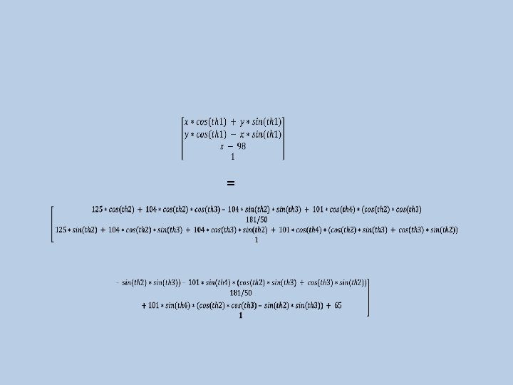
Transformation Matrix =

Transformation Matrix of Each Axis

Location Equation of End Effector T 09=T 01*T 12*T 23*T 34*T 45*T 56*T 67*T 78*T 89

Inverse Kinematics End Effector L 1 q 2 q 3 L 2 q 1 Goal L 3
")
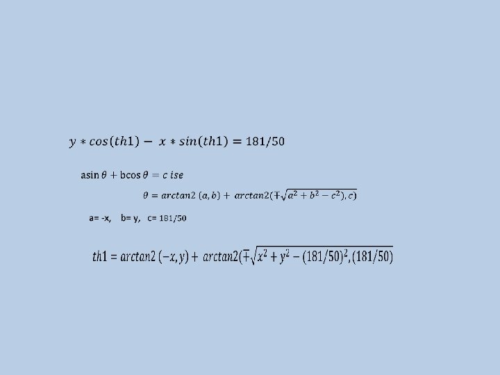
Diffuculties Invers Kinematics θ=Arctan 2(-k, pz )

Invers Kinematics Methods q. Analytical Solution of the Inverse Kinematic Problem q. Numerical Solution of the Inverse Kinematic Problem Ø Jacobian Inverse Methods Ø Newton Methods Ø IK using Sequential Monte Carlo Methods Ø Style or Mesh-based Inverse Kinematics Ø Heuristic Inverse Kinematics Algorithms

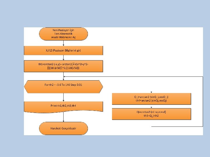
Invers Kinematics

Trajectory Analysis Yörünge analizi yaparak bir manipülatörün başlangıç pozisyonun istenilen pozisyona pürüzsüz hareketi

n n Work-space trajectories allow to consider directly possible constraints on the path (obstacles, path geometry, . . . ) that are more di�cult to take into consideration in the joint space (because of the non linear kineamtics) Joint space trajectories are computationally simpler and allow to consider problems due to singular configurations, actuation redundancy, velocity/acceleration constraints. Başlangıç Pozisyonu Bitiş Pozisyonu

Results Invers Kinematics

cubic equation Begining and Finish Position, Speed Value

Position equation Speed equation Acceralation equation
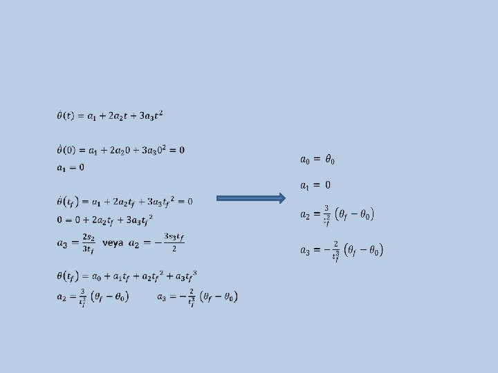

If end-effector passed waypoint

Trajectory Analysis of First Axis Start Position Finish Position Start Speed Finish Speed
 b) c) Th 1 için; a)Position-Time Graph b) Speed-Time Graph c)Acceleration-Time Graph")
a) b) c) Th 1 için; a)Position-Time Graph b) Speed-Time Graph c)Acceleration-Time Graph

A 2 Kâğıdına Çizilmiş Koordinat Düzelimi

Robot Uç İşlevcisinin X=230 mm, Y=45 mm, Z=28 mm pozisyonuna gidişi

Thank you for listened to us
- Slides: 72