Physics 214 1 Geometric Optics Huygens Principle Diffraction








- Slides: 40
Physics 214 1: Geometric Optics • Huygens Principle • Diffraction • Reflection • specular • diffuse • Refraction • Snells Law • Index of Refraction • Dispersion • Mirrors
• • • Images formed by refraction Lens Makers Equation Thin lenses Combination of thin lenses Aberration Optical Instruments
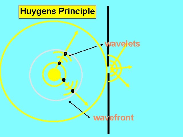
Huygens Principle wavelets wavefront
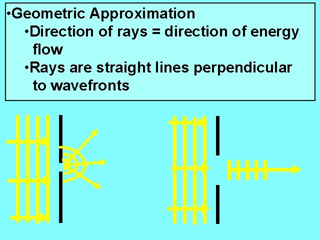
• Geometric Approximation • Direction of rays = direction of energy flow • Rays are straight lines perpendicular to wavefronts
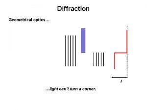
l = wavelength d =width of opening l » d cannot approximate as point source l << d no change in direction of light rays l >> d change in direction of light rays Û DIFFRACTION sharp shadows are cast when NO diffraction occurs
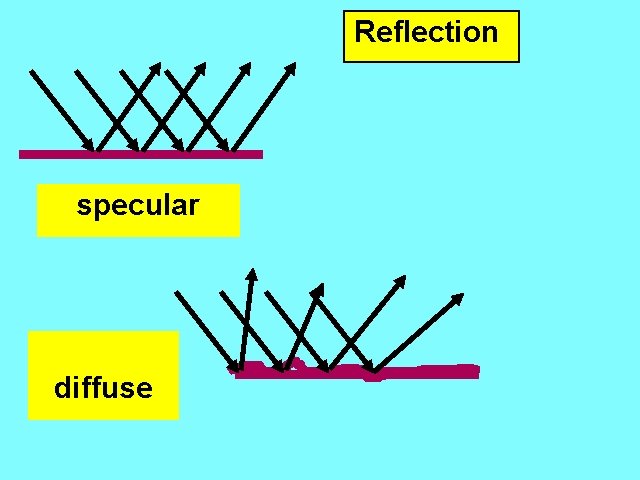
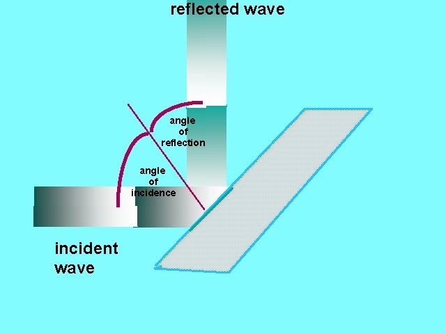
Reflection specular diffuse
reflected wave angle of reflection angle of incidence incident wave
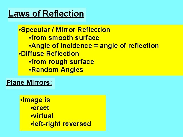
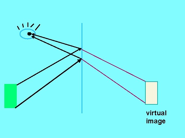
Laws of Reflection • Specular / Mirror Reflection • from smooth surface • Angle of incidence = angle of reflection • Diffuse Reflection • from rough surface • Random Angles Plane Mirrors: • Image is • erect • virtual • left-right reversed
virtual image
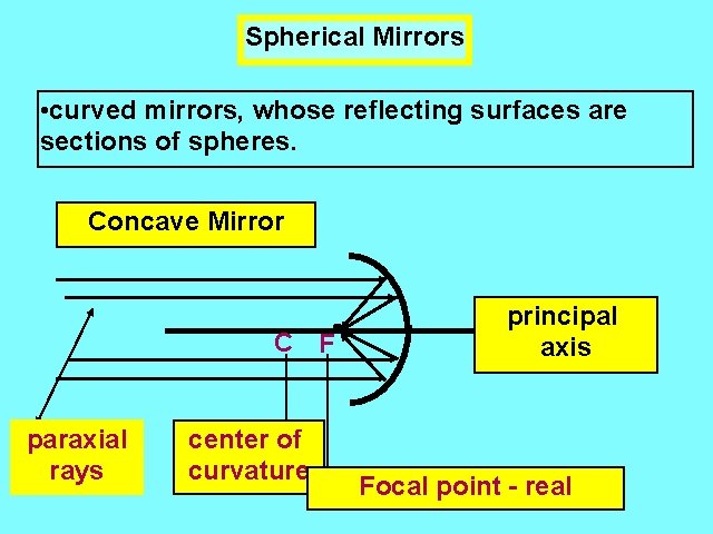
Spherical Mirrors • curved mirrors, whose reflecting surfaces are sections of spheres. Concave Mirror C F paraxial rays center of curvature principal axis Focal point - real
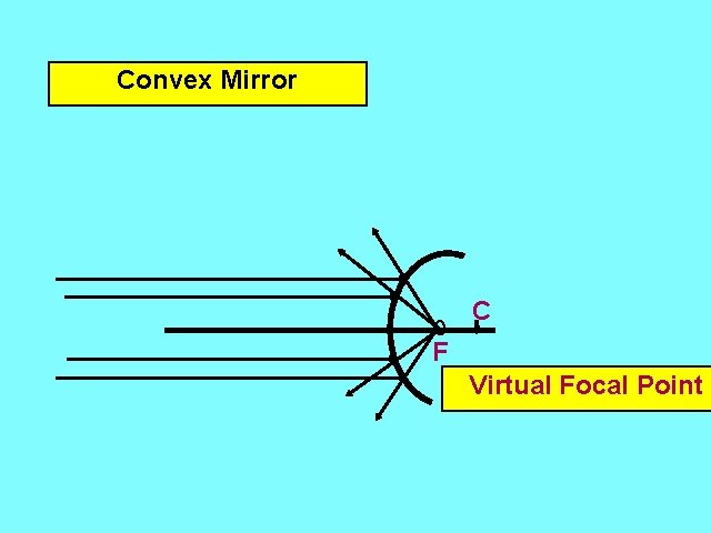
Convex Mirror C F Virtual Focal Point
Type of Mirro r Object Distance as Compared to Focal Length Characteristics of Image Concave d > 2 f real, inverted, diminished d = 2 f real, inverted, same size f < d < 2 f real, inverted, magnified d<f virtual, erect, magnified Convex for any d virtual, erect, diminished
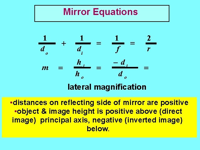
Mirror Equations 1 do m + = 1 di hi ho = 1 f = - di do 2 r = = lateral magnification • distances on reflecting side of mirror are positive • object & image height is positive above (direct image) principal axis, negative (inverted image) below.
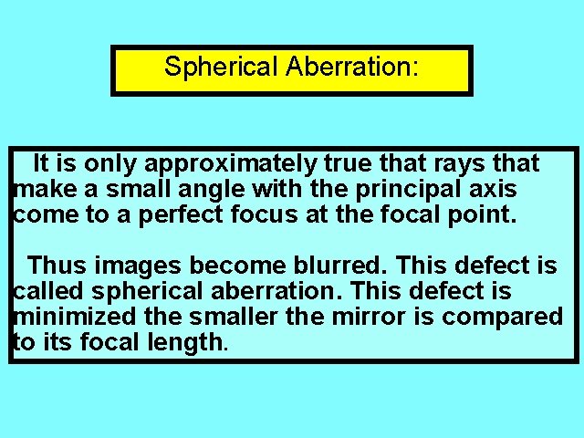
Spherical Aberration: It is only approximately true that rays that make a small angle with the principal axis come to a perfect focus at the focal point. Thus images become blurred. This defect is called spherical aberration. This defect is minimized the smaller the mirror is compared to its focal length.
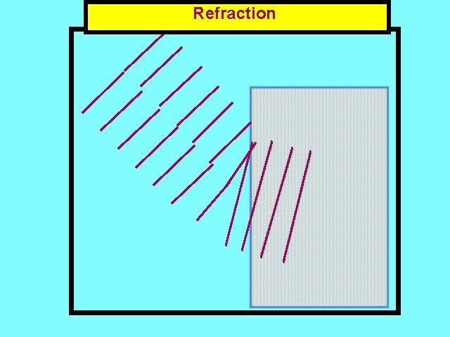
Refraction
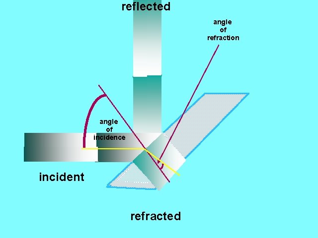
reflected angle of refraction angle of incidence incident refracted
• Speed of light is slower in denser materials • Index of refraction is greater • In denser medium angle of light ray to the normal of the surface between mediums is smaller than the corresponding angle in the less dense medium. • paths of light rays are reversible
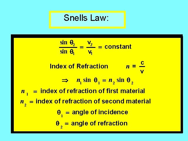
Snells Law: sin 2 v 2 = = constant sin 1 v 1 c n= Index of Refraction v Þ n 1 sin 1 = n 2 sin 2 n 1 = index of refraction of first material n 2 = index of refraction of second material 1 = angle of incidence 2 = angle of refraction
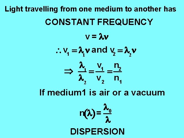
Light travelling from one medium to another has CONSTANT FREQUENCY v = ln v 1 = l 1 n and v 2 = l 2 n l 1 v 1 n 2 Þ = = l 2 v 2 n 1 If medium 1 is air or a vacuum l 0 n(l) = l DISPERSION
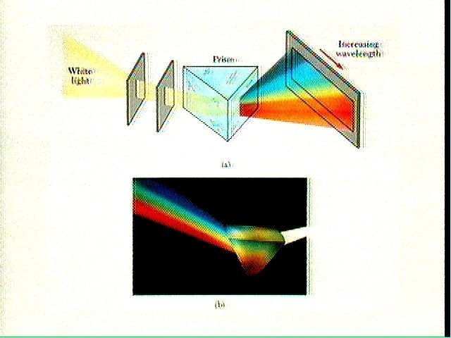
Continuous Spectra
reflected angle of incidence angle of refraction (b) incident (a) refracted transmitted
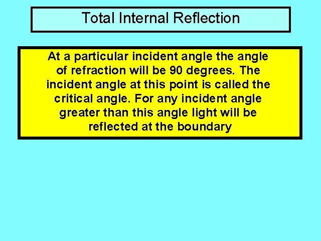
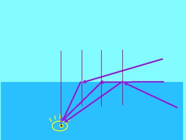
Total Internal Reflection At a particular incident angle the angle of refraction will be 90 degrees. The incident angle at this point is called the critical angle. For any incident angle greater than this angle light will be reflected at the boundary
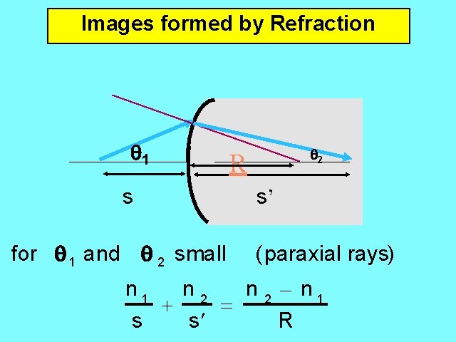
Images formed by Refraction 1 s for 1 and 2 small 2 R s’ (paraxial rays) n 1 n 2 - n 1 + = s s¢ R
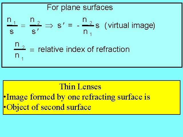
For plane surfaces n 1 n 2 s ( virtual image) = Þ s¢ = s s¢ n 1 n 2 º relative index of refraction n 1 Thin Lenses • Image formed by one refracting surface is • Object of second surface
The focal length of a lens is defined as the image distance S' when the object is at ¥, i. e. f = s¢ when s= ¥. æ 1 1ö 1 1 1 Þ = + = (n- 1)ç - ÷ è R 1 R 2ø f s s¢ Lens Maker Equation A thin lens has 2 focal points depending on whether incident rays come from left or right. h¢ s¢ Lateral magnification = m = = h s
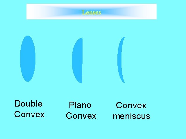
Lenses Double Convex Plano Convex meniscus
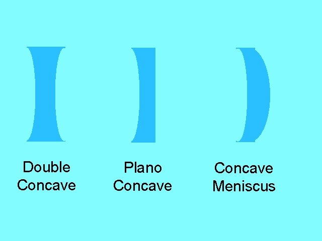
Double Concave Plano Concave Meniscus
Ty pe of Le n s Conv e x Object Distance as Compared to Focal Length d > 2 f real, inverted, diminished d = 2 f real, inverted, same size f < d < 2 f real, inverted, magnified d=f d<f Concave Characteristics of Image for any d no image formed v i r t u a l , er e ct , m a g ni f i e d v i r t ua l , er ect , d i m i n i sh ed
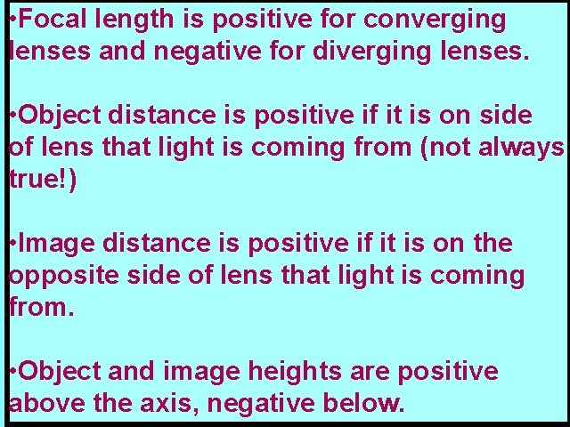
• Focal length is positive for converging lenses and negative for diverging lenses. • Object distance is positive if it is on side of lens that light is coming from (not always true!) • Image distance is positive if it is on the opposite side of lens that light is coming from. • Object and image heights are positive above the axis, negative below.
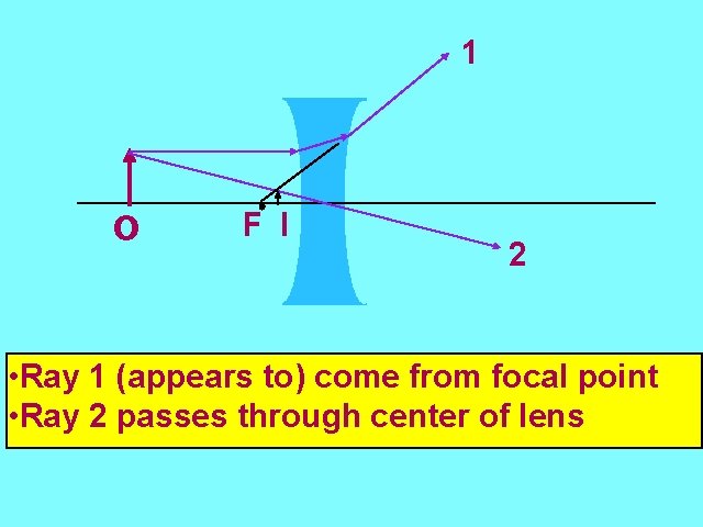
1 o F I 2 • Ray 1 (appears to) come from focal point • Ray 2 passes through center of lens
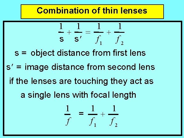
Combination of thin lenses 1 1 + = + f 1 f 2 s s¢ s = object distance from first lens s ¢ = image distance from second lens if the lenses are touching they act as a single lens with focal length 1 1 1 = + f f 1 f 2
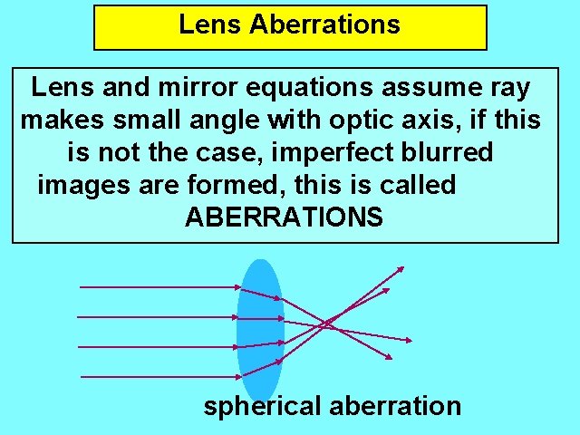
Lens Aberrations Lens and mirror equations assume ray makes small angle with optic axis, if this is not the case, imperfect blurred images are formed, this is called ABERRATIONS spherical aberration
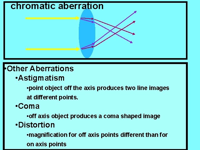
chromatic aberration • Other Aberrations • Astigmatism • point object off the axis produces two line images at different points. • Coma • off axis object produces a coma shaped image • Distortion • magnification for off axis points different than for on axis points
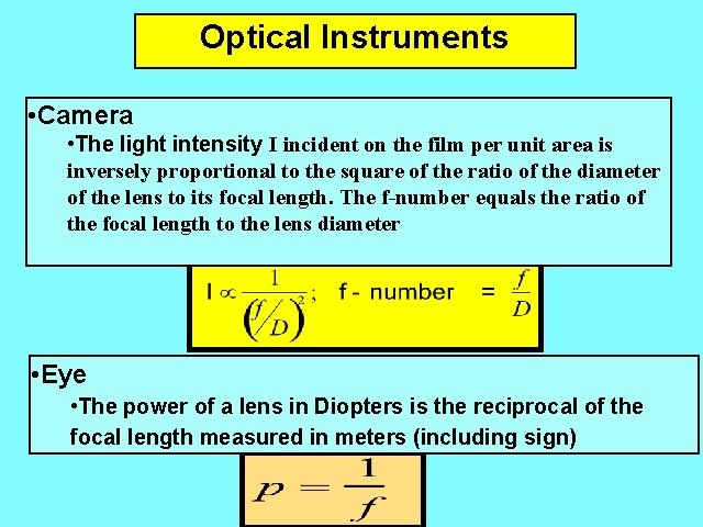
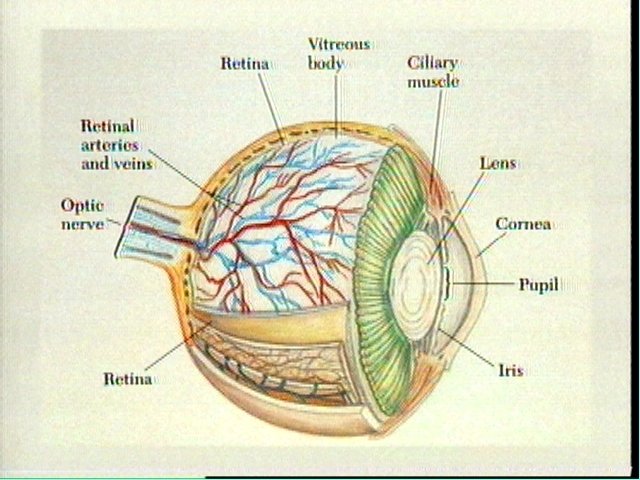
Optical Instruments • Camera • The light intensity I incident on the film per unit area is inversely proportional to the square of the ratio of the diameter of the lens to its focal length. The f-number equals the ratio of the focal length to the lens diameter • Eye • The power of a lens in Diopters is the reciprocal of the focal length measured in meters (including sign)
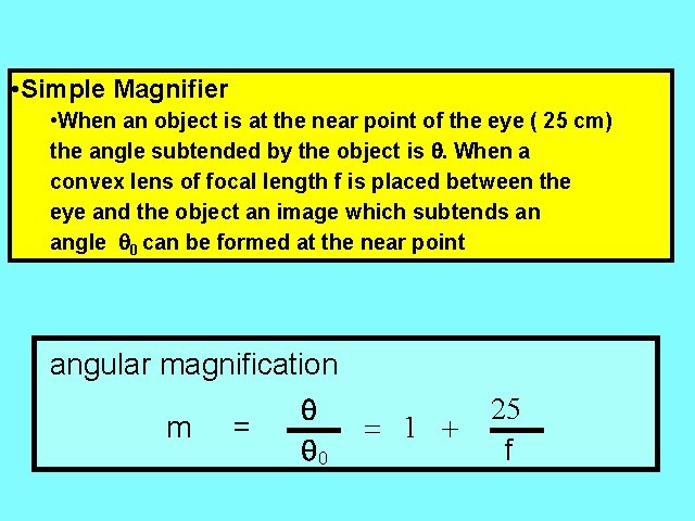
• Simple Magnifier • When an object is at the near point of the eye ( 25 cm) the angle subtended by the object is When a convex lens of focal length f is placed between the eye and the object an image which subtends an angle 0 can be formed at the near point angular magnification m = 0 = 1 + 25 f
• Compound Microscope L æç 25 ö ÷ M = f 0 è f e ø • objective focal length of f 0 • eye piece of focal length fe • the two lenses are separated by a distance L • For object located just beyond focal point of objective, the two lenses combined form an enlarged virtual and inverted image of lateral magnification M
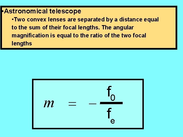
• Astronomical telescope • Two convex lenses are separated by a distance equal to the sum of their focal lengths. The angular magnification is equal to the ratio of the two focal lengths m = - f 0 fe