PC Modem Control The 8250 UART supplied with
- Slides: 14
PC Modem Control • The 8250 UART supplied with the PC supports a limited number of RS-232 -C modem functions: - The ability to control modem conditions (through Modem Control Register). - The ability to determine the modem’s status (from the Modem Status Register). • The UART can be programmed to interrupt the PC when modem status changes occur.
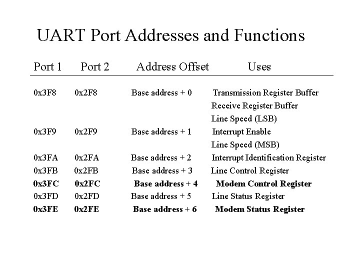
UART Port Addresses and Functions Port 1 Port 2 Address Offset 0 x 3 F 8 0 x 2 F 8 Base address + 0 0 x 3 F 9 0 x 2 F 9 Base address + 1 0 x 3 FA 0 x 3 FB 0 x 3 FC 0 x 3 FD 0 x 3 FE 0 x 2 FA 0 x 2 FB 0 x 2 FC 0 x 2 FD 0 x 2 FE Base address + 2 Base address + 3 Base address + 4 Base address + 5 Base address + 6 Uses Transmission Register Buffer Receive Register Buffer Line Speed (LSB) Interrupt Enable Line Speed (MSB) Interrupt Identification Register Line Control Register Modem Control Register Line Status Register Modem Status Register
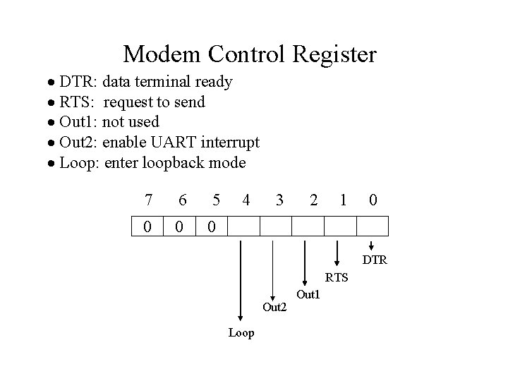
Modem Control Register · DTR: data terminal ready · RTS: request to send · Out 1: not used · Out 2: enable UART interrupt · Loop: enter loopback mode 7 6 0 0 5 4 3 2 1 0 0 DTR RTS Out 2 Loop Out 1
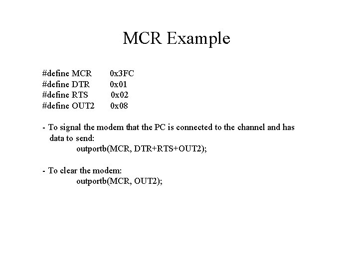
MCR Example #define MCR #define DTR #define RTS #define OUT 2 0 x 3 FC 0 x 01 0 x 02 0 x 08 - To signal the modem that the PC is connected to the channel and has data to send: outportb(MCR, DTR+RTS+OUT 2); - To clear the modem: outportb(MCR, OUT 2);
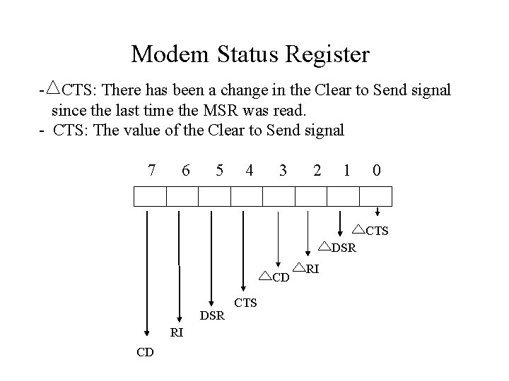
Modem Status Register - CTS: There has been a change in the Clear to Send signal since the last time the MSR was read. - CTS: The value of the Clear to Send signal 7 6 5 4 3 2 1 0 CTS DSR CD DSR RI CD CTS RI
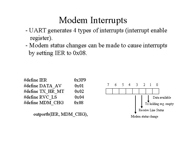
Modem Interrupts - UART generates 4 types of interrupts (interrupt enable register). - Modem status changes can be made to cause interrupts by setting IER to 0 x 08. #define IER #define DATA_AV #define TX_HR_MT #define RVC_LS #define MDM_CHG 0 x 3 F 9 0 x 01 0 x 02 0 x 04 0 x 08 outportb(IER, MDM_CHG), 7 6 5 4 3 2 1 0 Data available Tx holding reg. empty Receive Line Status Modem status change
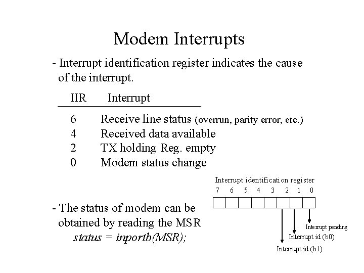
Modem Interrupts - Interrupt identification register indicates the cause of the interrupt. IIR 6 4 2 0 Interrupt Receive line status (overrun, parity error, etc. ) Received data available TX holding Reg. empty Modem status change Interrupt identification register 7 - The status of modem can be obtained by reading the MSR status = inportb(MSR); 6 5 4 3 2 1 0 Interrupt pending Interrupt id (b 0) Interrupt id (b 1)
Example: Commkit External Modem - Extends the point-to-point utility to handle modems. - The following modem status changes are recognized: CTS, DSR, RI, RLSD (CD) - Once carrier is detected, the modem enters the DSR state and signals both DSR and RLSD to the UART. - Upon detection of DSR and DLSD, the DTE responds with DTR and RTS. - At this point, DTE is connected DCE and communications can commence.
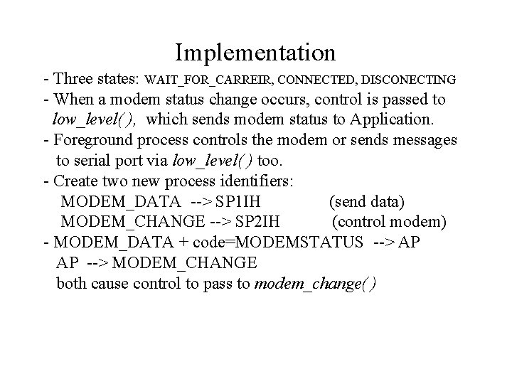
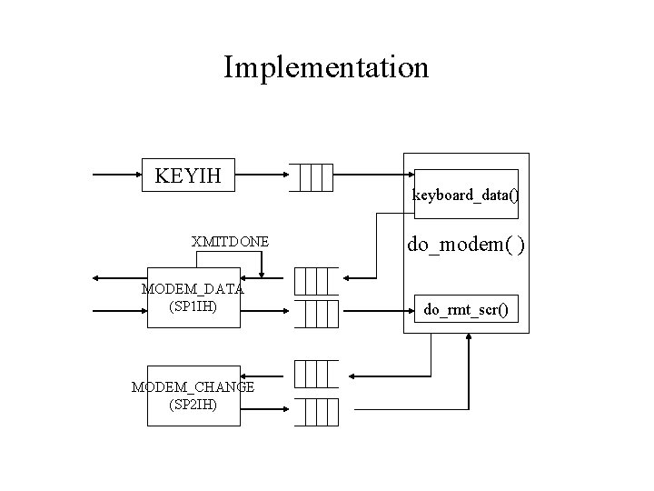
Implementation - Three states: WAIT_FOR_CARREIR, CONNECTED, DISCONECTING - When a modem status change occurs, control is passed to low_level( ), which sends modem status to Application. - Foreground process controls the modem or sends messages to serial port via low_level( ) too. - Create two new process identifiers: MODEM_DATA --> SP 1 IH (send data) MODEM_CHANGE --> SP 2 IH (control modem) - MODEM_DATA + code=MODEMSTATUS --> AP AP --> MODEM_CHANGE both cause control to pass to modem_change( )
Implementation KEYIH XMITDONE MODEM_DATA (SP 1 IH) MODEM_CHANGE (SP 2 IH) keyboard_data() do_modem( ) do_rmt_scr()
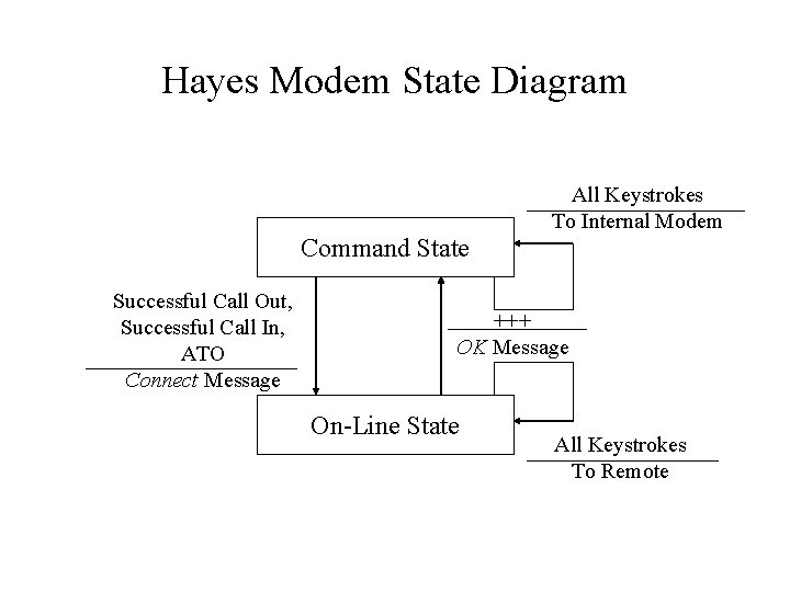
Hayes’ Commands - Not all UART Manufacturers conform to RS-232 -C signals. - Programs may not be portable across different modems. - Many modems support Hayes’ commands, a set of textual strings that are recognized and interpreted by the modem. - Hayes modem has a front-end that interprets the modem commands issued by the application software, converting them into the signals required by the modem. - When first initialized, the front-end is in “command” state, interpreting any data supplied to it. - Once a connection is established with another modem, the front-end enters the “on-line” state, passing data directly to modem.
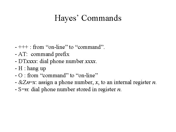
Hayes’ Commands - +++ : from “on-line” to “command”. - AT: command prefix - DTxxxx: dial phone number xxxx. - H : hang up - O : from “command” to “on-line” - &Zn=x: assign a phone number, x, to an internal register n. - S=n: dial phone number stored in register n.
Hayes Modem State Diagram All Keystrokes To Internal Modem Command State Successful Call Out, Successful Call In, ATO Connect Message +++ OK Message On-Line State All Keystrokes To Remote
Example: Commkit Internal Modem - Internal Modem is installed as a card in PC. - Most internal modems support Hayes’ AT commands. - For a Hayes modem, - The control software is not in direct communication with UART; rather, all modem control signals are via the AT Commands. - All modem status changes are interpreted by the internal modem and returned to the control software as text via the UART’s data-available interrupt.