OPUS Online Positioning User Service NATIONAL OCEANIC AND

- Slides: 39
OPUS Online Positioning User Service NATIONAL OCEANIC AND ATMOSPHERIC ADMINISTRATION http: //www. ngs. noaa. gov/OPUS/ National Geodetic Survey opus@ngs. noaa. gov Positioning America for the Future National Ocean Service
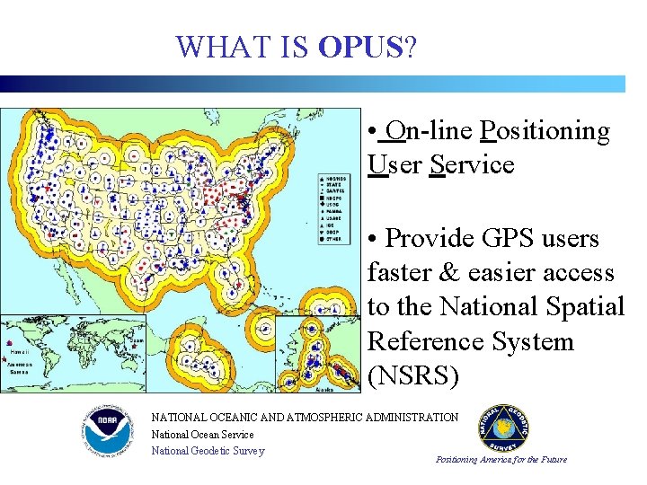
WHAT IS OPUS? • On-line Positioning User Service • Provide GPS users faster & easier access to the National Spatial Reference System (NSRS) NATIONAL OCEANIC AND ATMOSPHERIC ADMINISTRATION National Ocean Service National Geodetic Survey Positioning America for the Future
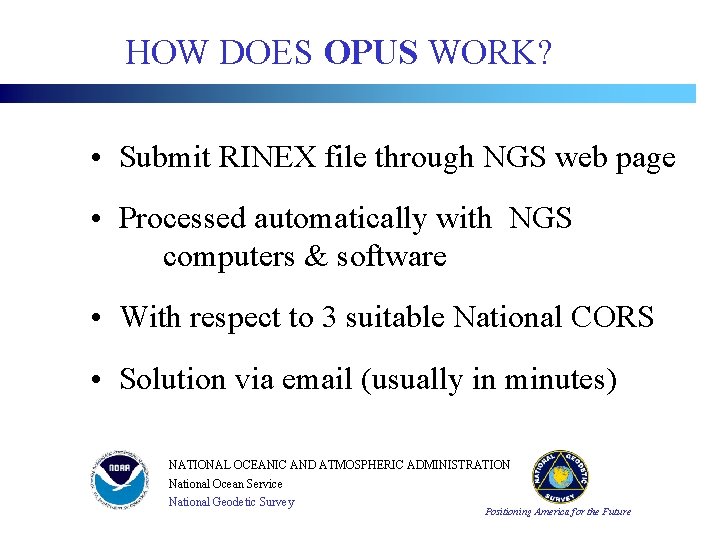
HOW DOES OPUS WORK? • Submit RINEX file through NGS web page • Processed automatically with NGS computers & software • With respect to 3 suitable National CORS • Solution via email (usually in minutes) NATIONAL OCEANIC AND ATMOSPHERIC ADMINISTRATION National Ocean Service National Geodetic Survey Positioning America for the Future
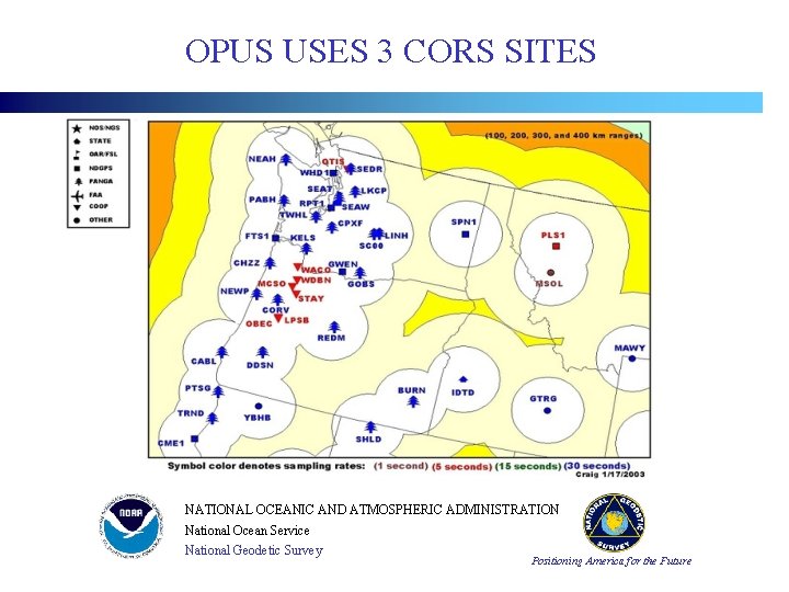
OPUS USES 3 CORS SITES NATIONAL OCEANIC AND ATMOSPHERIC ADMINISTRATION National Ocean Service National Geodetic Survey Positioning America for the Future
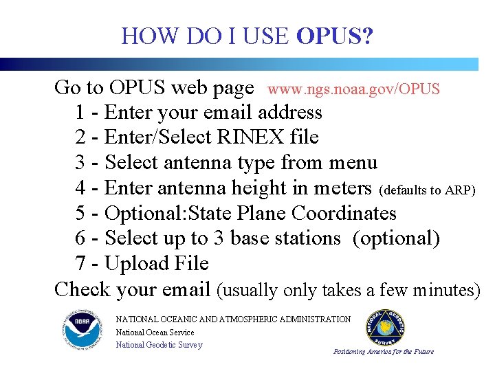
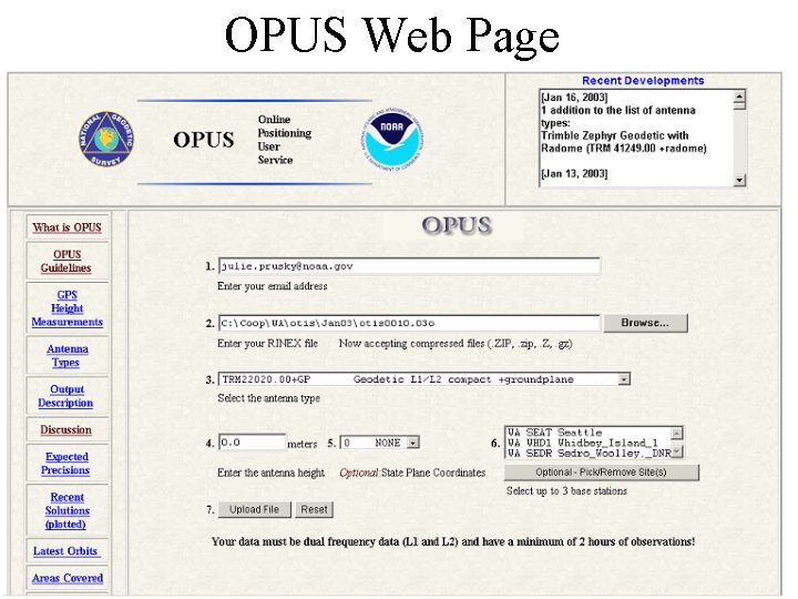
HOW DO I USE OPUS? Go to OPUS web page www. ngs. noaa. gov/OPUS 1 - Enter your email address 2 - Enter/Select RINEX file 3 - Select antenna type from menu 4 - Enter antenna height in meters (defaults to ARP) 5 - Optional: State Plane Coordinates 6 - Select up to 3 base stations (optional) 7 - Upload File Check your email (usually only takes a few minutes) NATIONAL OCEANIC AND ATMOSPHERIC ADMINISTRATION National Ocean Service National Geodetic Survey Positioning America for the Future
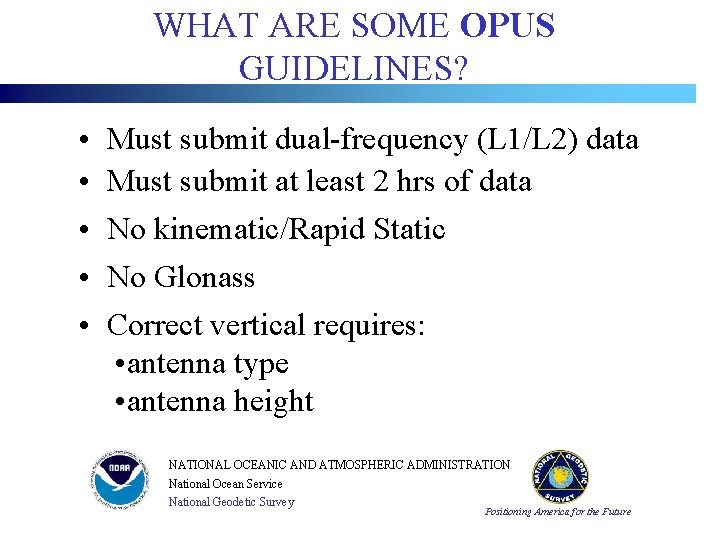
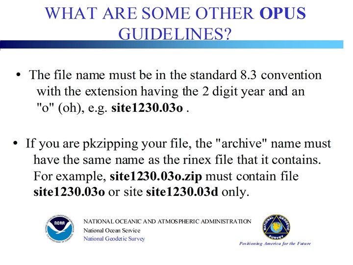
WHAT ARE SOME OPUS GUIDELINES? • • • Must submit dual-frequency (L 1/L 2) data Must submit at least 2 hrs of data No kinematic/Rapid Static No Glonass Correct vertical requires: • antenna type • antenna height NATIONAL OCEANIC AND ATMOSPHERIC ADMINISTRATION National Ocean Service National Geodetic Survey Positioning America for the Future
NATIONAL OCEANIC AND ATMOSPHERIC ADMINISTRATION National Ocean Service National Geodetic Survey Positioning America for the Future
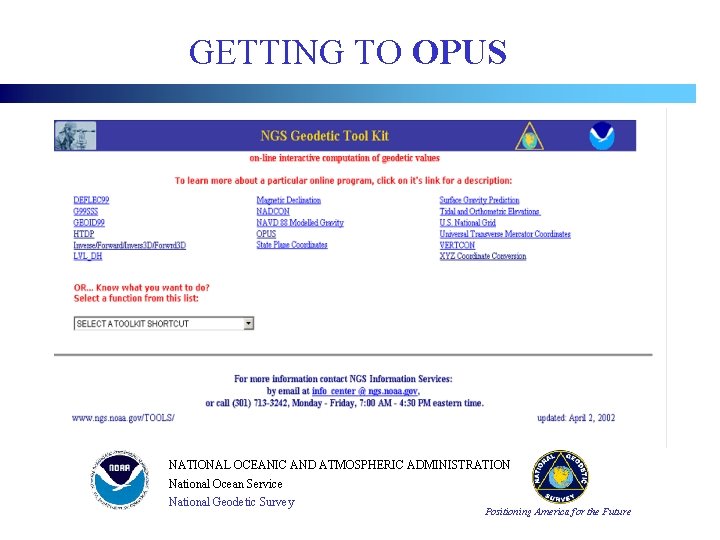
GETTING TO OPUS NATIONAL OCEANIC AND ATMOSPHERIC ADMINISTRATION National Ocean Service National Geodetic Survey Positioning America for the Future
OPUS Web Page NATIONAL OCEANIC AND ATMOSPHERIC ADMINISTRATION National Ocean Service National Geodetic Survey Positioning America for the Future
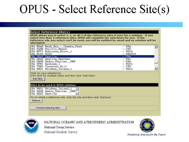
OPUS - Select Reference Site(s) NATIONAL OCEANIC AND ATMOSPHERIC ADMINISTRATION National Ocean Service National Geodetic Survey Positioning America for the Future
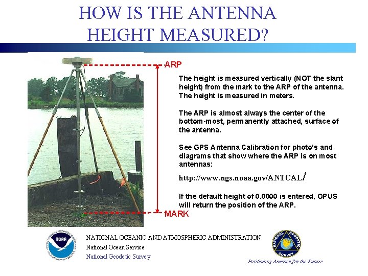
HOW IS THE ANTENNA HEIGHT MEASURED? ARP The height is measured vertically (NOT the slant height) from the mark to the ARP of the antenna. The height is measured in meters. The ARP is almost always the center of the bottom-most, permanently attached, surface of the antenna. See GPS Antenna Calibration for photo’s and diagrams that show where the ARP is on most antennas: http: //www. ngs. noaa. gov/ANTCAL/ If the default height of 0. 0000 is entered, OPUS will return the position of the ARP. MARK NATIONAL OCEANIC AND ATMOSPHERIC ADMINISTRATION National Ocean Service National Geodetic Survey Positioning America for the Future
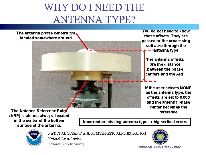
WHY DO I NEED THE ANTENNA TYPE? You do not need to know these offsets. They are passed to the processing software through the antenna type The antenna phase centers are located somewhere around here. The antenna offsets are the distance between the phase centers and the ARP The Antenna Reference Point (ARP) is almost always located in the center of the bottom surface of the antenna. If the user selects NONE as the antenna type, the offsets are set to 0. 000 and the antenna phase center becomes the reference Incorrect or missing antenna type big vertical errors NATIONAL OCEANIC AND ATMOSPHERIC ADMINISTRATION National Ocean Service National Geodetic Survey Positioning America for the Future
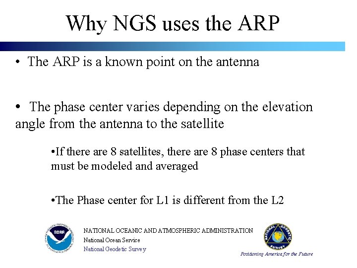
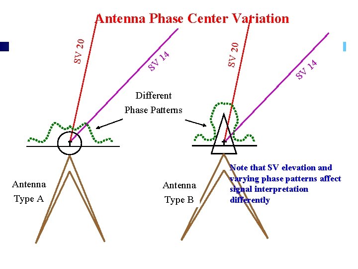
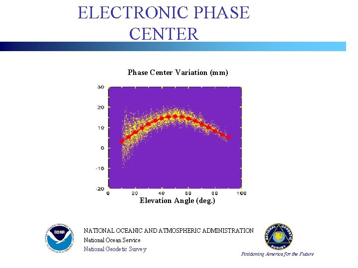
Why NGS uses the ARP • The ARP is a known point on the antenna • The phase center varies depending on the elevation angle from the antenna to the satellite • If there are 8 satellites, there are 8 phase centers that must be modeled and averaged • The Phase center for L 1 is different from the L 2 NATIONAL OCEANIC AND ATMOSPHERIC ADMINISTRATION National Ocean Service National Geodetic Survey Positioning America for the Future
Antenna Type A . 14. SV. Different. Phase Patterns. . Antenna. Type B. . . SV 20 Antenna Phase Center Variation SV 14 Note that SV elevation and varying phase patterns affect signal interpretation differently NATIONAL OCEANIC AND ATMOSPHERIC ADMINISTRATION National Ocean Service National Geodetic Survey Positioning America for the Future
ELECTRONIC PHASE CENTER Phase Center Variation (mm) Elevation Angle (deg. ) NATIONAL OCEANIC AND ATMOSPHERIC ADMINISTRATION National Ocean Service National Geodetic Survey Positioning America for the Future
GPS Antenna Phase Pattern Calibrations http: //www. grdl. noaa. gov/GRD/GPS/Projects/ANTCAL Each antenna type has a unique phase pattern GPS antennas must be calibrated Mixing uncorrected antenna types can produce errors of up to 10 cm in the vertical component NGS is at the forefront in relative field calibration of GPS antennas NGS maintains a calibration database with parameters for 88 antenna types (03 -26 -01) NATIONAL OCEANIC AND ATMOSPHERIC ADMINISTRATION National Ocean Service National Geodetic Survey Positioning America for the Future
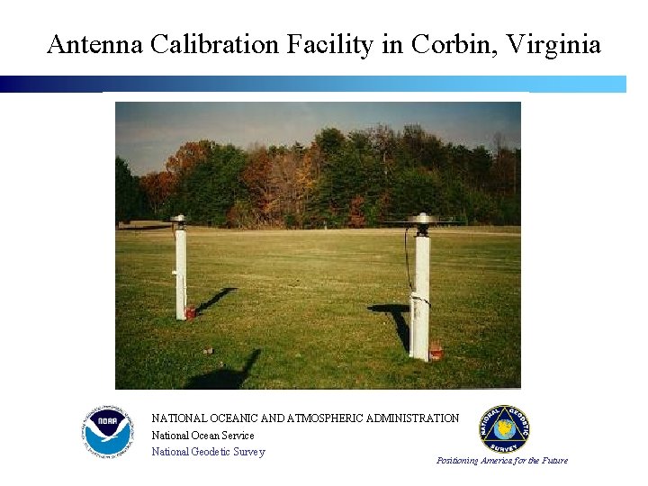
Antenna Calibration Facility in Corbin, Virginia NATIONAL OCEANIC AND ATMOSPHERIC ADMINISTRATION National Ocean Service National Geodetic Survey Positioning America for the Future
HOW ARE OPUS POSITIONS COMPUTED? • NGS PAGES software • Ionosphere free • Tropospheric scale height adjusted • Fixed ambiguities • Average solution to 3 suitable CORS • ITRF and NAD 83 positions returned NATIONAL OCEANIC AND ATMOSPHERIC ADMINISTRATION National Ocean Service National Geodetic Survey Positioning America for the Future
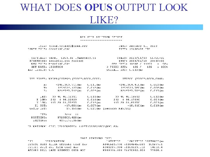
WHAT DOES OPUS OUTPUT LOOK LIKE? NATIONAL OCEANIC AND ATMOSPHERIC ADMINISTRATION National Ocean Service National Geodetic Survey Positioning America for the Future
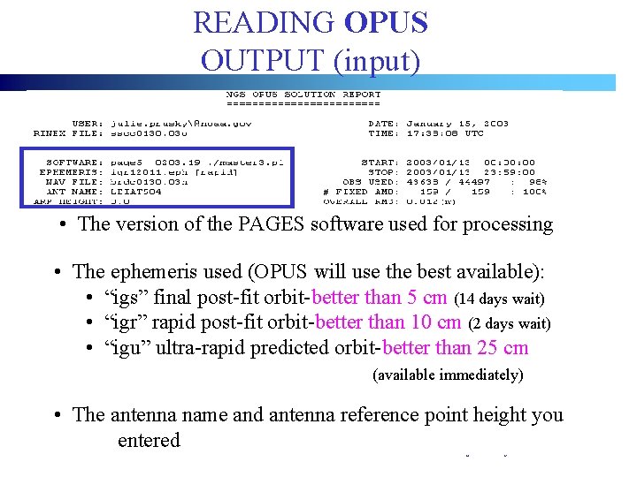
READING OPUS OUTPUT (input) • The version of the PAGES software used for processing • The ephemeris used (OPUS will use the best available): • “igs” final post-fit orbit-better than 5 cm (14 days wait) • “igr” rapid post-fit orbit-better than 10 cm (2 days wait) • “igu” ultra-rapid predicted orbit-better than 25 cm (available immediately) NATIONAL OCEANIC AND ATMOSPHERIC ADMINISTRATION • The antenna name and antenna reference point height you National Ocean Service entered National Geodetic Survey Positioning America for the Future
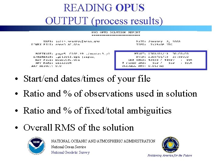
READING OPUS OUTPUT (process results) • Start/end dates/times of your file • Ratio and % of observations used in solution • Ratio and % of fixed/total ambiguities • Overall RMS of the solution NATIONAL OCEANIC AND ATMOSPHERIC ADMINISTRATION National Ocean Service National Geodetic Survey Positioning America for the Future
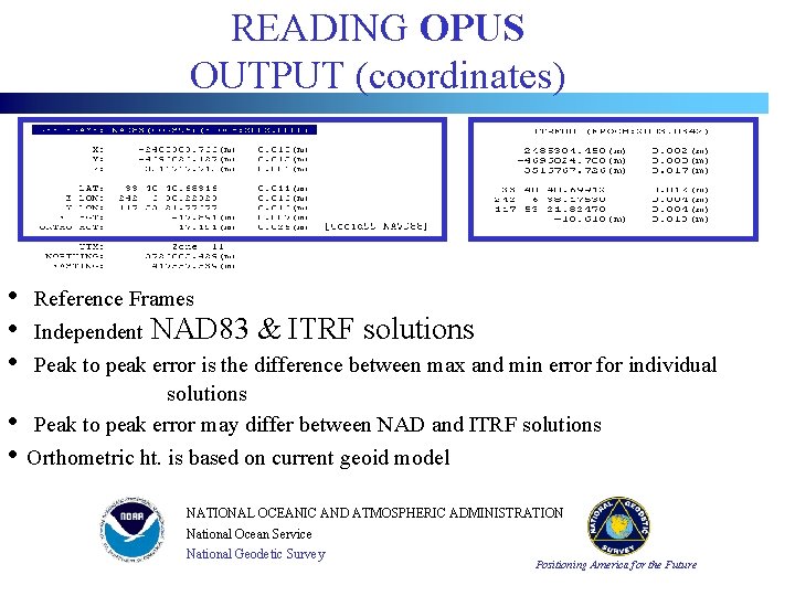
READING OPUS OUTPUT (coordinates) • • • Reference Frames Independent NAD 83 & ITRF solutions Peak to peak error is the difference between max and min error for individual solutions Peak to peak error may differ between NAD and ITRF solutions • • Orthometric ht. is based on current geoid model NATIONAL OCEANIC AND ATMOSPHERIC ADMINISTRATION National Ocean Service National Geodetic Survey Positioning America for the Future
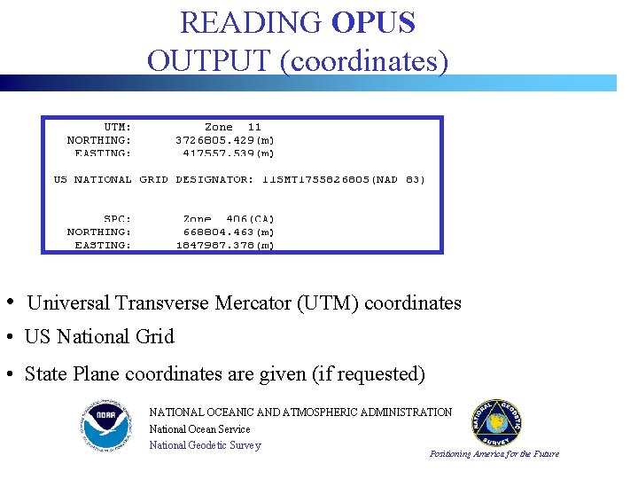
READING OPUS OUTPUT (coordinates) • Universal Transverse Mercator (UTM) coordinates • US National Grid • State Plane coordinates are given (if requested) NATIONAL OCEANIC AND ATMOSPHERIC ADMINISTRATION National Ocean Service National Geodetic Survey Positioning America for the Future
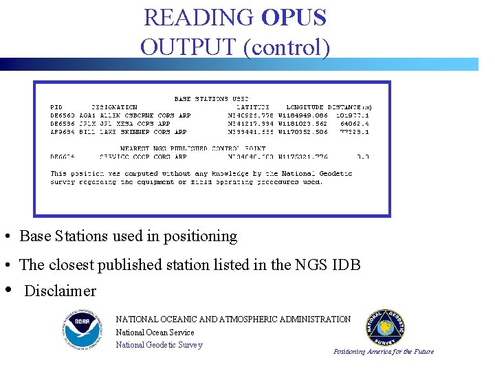
READING OPUS OUTPUT (control) • Base Stations used in positioning • The closest published station listed in the NGS IDB • Disclaimer NATIONAL OCEANIC AND ATMOSPHERIC ADMINISTRATION National Ocean Service National Geodetic Survey Positioning America for the Future
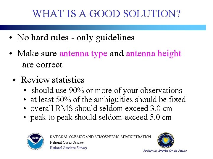
WHAT IS A GOOD SOLUTION? • No hard rules - only guidelines • Make sure antenna type and antenna height are correct • Review statistics • should use 90% or more of your observations • at least 50% of the ambiguities should be fixed • overall RMS should seldom exceed 3. 0 cm • peak to peak should seldom exceed 5. 0 cm NATIONAL OCEANIC AND ATMOSPHERIC ADMINISTRATION National Ocean Service National Geodetic Survey Positioning America for the Future
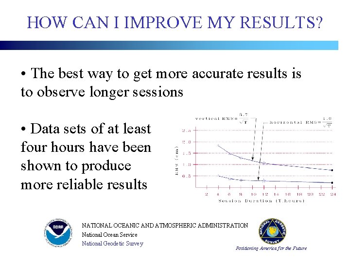
HOW CAN I IMPROVE MY RESULTS? • The best way to get more accurate results is to observe longer sessions • Data sets of at least four hours have been shown to produce more reliable results NATIONAL OCEANIC AND ATMOSPHERIC ADMINISTRATION National Ocean Service National Geodetic Survey Positioning America for the Future
HOW DO I GET HELP? • First use the Links on the OPUS page • detailed discussions of guidelines • description of processing techniques • description of output • guidelines for successful use • Submit specific questions at OPUS web page • http: //www. ngs. noaa. gov/OPUS/ NATIONAL OCEANIC AND ATMOSPHERIC ADMINISTRATION National Ocean Service National Geodetic Survey Positioning America for the Future
WHAT CHANGES ARE PLANNED IN THE FUTURE? • Inclusion of Cooperative CORS in the base station selection process • Better treatment of RINEX-2 header errors is being implemented. Some translators are not compliant with the RINEX-2 standard • Single frequency data processing is being considered NATIONAL OCEANIC AND ATMOSPHERIC ADMINISTRATION National Ocean Service National Geodetic Survey Positioning America for the Future
QUESTIONS? NATIONAL OCEANIC AND ATMOSPHERIC ADMINISTRATION http: //www. ngs. noaa. gov/OPUS/ National Geodetic Survey opus@ngs. noaa. gov Positioning America for the Future National Ocean Service
Demonstration Application II NATIONAL OCEANIC AND ATMOSPHERIC ADMINISTRATION National Ocean Service National Geodetic Survey Positioning America for the Future
CONTROLLING A BRIDGE SURVEY The accompanying slides were presented at the 2002 CORS Forum by Gary Thompson of the North Carolina Department of Transportation. NATIONAL OCEANIC AND ATMOSPHERIC ADMINISTRATION National Ocean Service National Geodetic Survey Positioning America for the Future
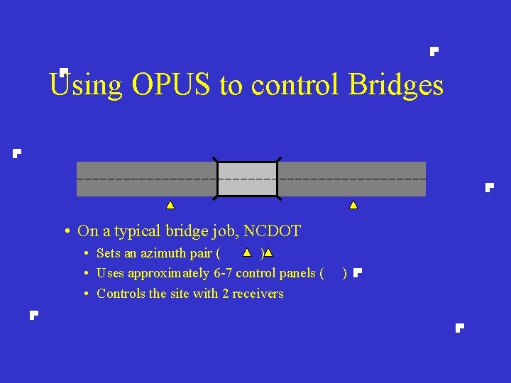
Using OPUS to control Bridges • On a typical bridge job, NCDOT • Sets an azimuth pair ( ) • Uses approximately 6 -7 control panels ( • Controls the site with 2 receivers )
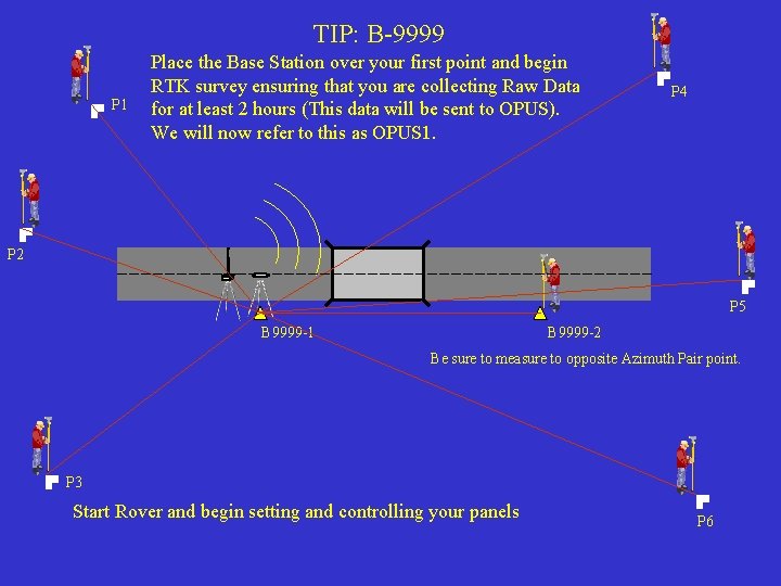
TIP: B-9999 P 1 Place the Base Station over your first point and begin RTK survey ensuring that you are collecting Raw Data for at least 2 hours (This data will be sent to OPUS). We will now refer to this as OPUS 1. P 4 P 2 P 5 B 9999 -1 B 9999 -2 Be sure to measure to opposite Azimuth Pair point. P 3 Start Rover and begin setting and controlling your panels P 6
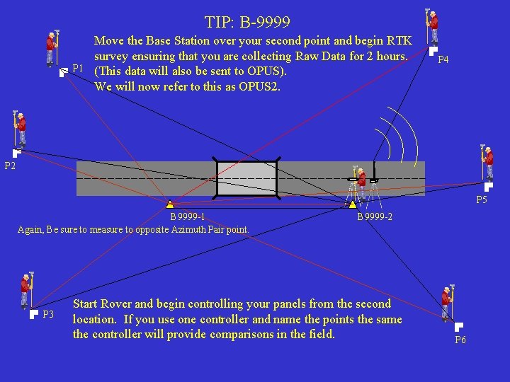
TIP: B-9999 P 1 Move the Base Station over your second point and begin RTK survey ensuring that you are collecting Raw Data for 2 hours. (This data will also be sent to OPUS). We will now refer to this as OPUS 2. P 4 P 2 P 5 B 9999 -1 Again, Be sure to measure to opposite Azimuth Pair point. P 3 B 9999 -2 Start Rover and begin controlling your panels from the second location. If you use one controller and name the points the same the controller will provide comparisons in the field. P 6
Field Work is now complete. The following steps need to be taken to finish the process:
Office Process • Download the Raw Data and RTK dc files • Convert both blocks of raw data to RINEX format using Trimble’s utility • Upload the files to: http: //www. ngs. noaa. gov/OPUS/ • Receive the results from OPUS via email in minutes
Continued. . . • Import the dc file into Trimble Geomatics Office • Update the initial base position for the first base to the coordinates provided by OPUS 1 • After a recompute, everything in the dc file should be corrected relative to the first base location (OPUS 1)
Continued. . . • The position for OPUS 2 is only used for comparison to what was derived from OPUS 1 • Coordinates can now be utilized as needed
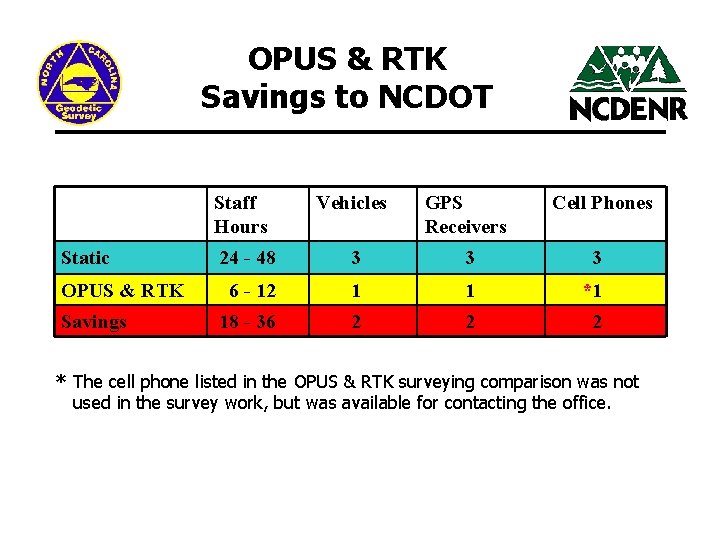
OPUS & RTK Savings to NCDOT Staff Hours Static OPUS & RTK Savings Vehicles GPS Receivers Cell Phones 24 - 48 3 3 3 6 - 12 1 1 *1 18 - 36 2 2 2 * The cell phone listed in the OPUS & RTK surveying comparison was not used in the survey work, but was available for contacting the office.