NESS Network of Environmental and Seismic Stations NASA


: Delta 2925 H Flight schedule: liftoff Mars arrival Ls")


 ~855 g http: //mars. jpl. nasa. gov/MPF/mpf/sci_desc.")

")
 22 -5 mm, 10 mm × 3 10**-4 -10 Hz, 10**-2")


 – Failure to establish seismometer contact with the")


 Science Team Principal Investigator - Algorithm Development -")


- Slides: 55
NESS Network of Environmental and Seismic Stations
NASA Solar System Roadmap Objective 6 Understand the current state and evolution of the ATMOSPHERE, surface, and INTERIOR of Mars
Mars Exploration Program Goals • • Goal 1: Determine if Life ever arose Goal 2: Characterize the Climate Goal 3: Characterize the Geology Goal 4: Prepare for Human Exploration
Mission Objective • Determine the state and structure of the Martian interior and atmosphere using a network of stationary landers. • Assess geologic hazards and long-term variations in climate/radiation environment in preparation for human exploration
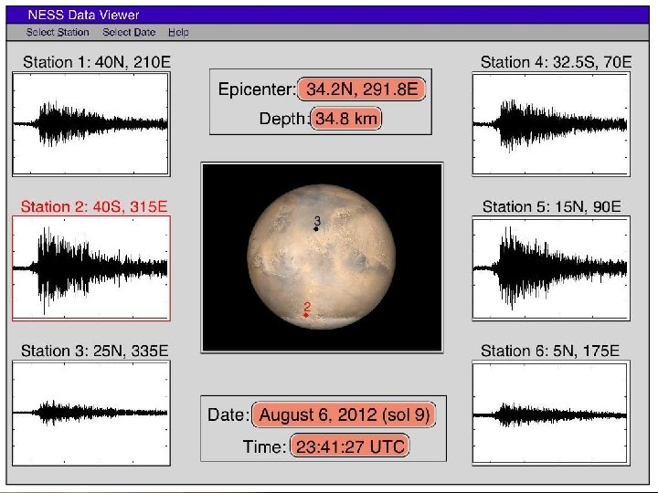
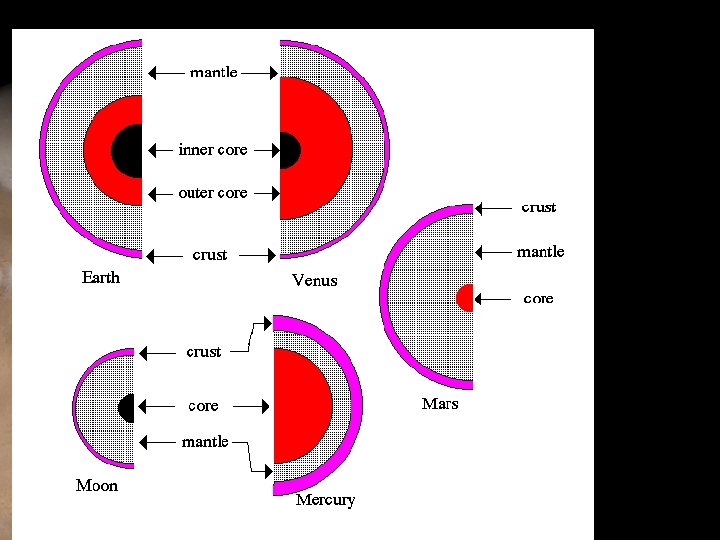
NESS Science Goals • Current seismic activity – How active is Mars? – Temporal and spatial distribution of Mars-quakes • Planet interior – Composition and properties of layers – Size and state of core • Global climate data – Global coverage from several meteorological stations – Concurrent data from 4 locations – Radiation & habitability for humans • Geology of landing site – Panoramic camera for context – Change in environment with the weather over the year
Science Objectives Measurement Objectives Instrumentation Requirement s Data Products Geophysics & Seismicity 1. Size and frequency of Mars -Quakes 2. Thickness and state of core, mantle, and crust 3. Variations of interior with latitude and longitude Ideally, seismic measurements from 0. 1 m. Hz-100 Hz and 0. 11 x 10 -8 m/s 2 peak ground acceleration 1 (3 -axis) Very Broad Band Seismometer (0. 1 m. Hz 10 Hz), 1 (3 -axis) short period, high frequency microseismometer (10 Hz 100 Hz). 4 Landers, good ground-coupling, 1 Earth year primary mission to maximize probability of Marsquake detection Continuous daytime collection and limited nightime collection of 3 component (X, Y, Z) seismograms from 2 seismometers on each lander Atmospheric pressure: 1 mbar-14 mbars, temperature: 125 -300 K, Wind speed and direction: 0. 1 -100 m/s, UV: 200 -400 nm wavelength (1) Phoenix or Mars Polar Lander-Type Meteorology Package including: thermocouple, barometer, anemometer and UV radiation sensor 1 Earth year to track seasonal climatic variation at multiple locations Continuous daytime collection and limited nightime collection of atmospheric measurements 3 -color (RGB) stereo images at IFOV: 0. 28 mrad at 1. 5 m to infinity. Subframed opacity measurements with 4 th neutral density sun filter. (1) MER-Type Panoramic camera Gimballed mast: 360 o azimuth range, +/- 90 o elevation range Image data 4. Correlation of seismic activity with major geologic and tectonic features Climate & Meteorology 1. Air pressure, temperature 2. Wind speed and direction 3. UV Radiation Geologic & Geomorphic Context 1. Images of landing site 2. Changes in landscape and atmospheric opacity with seasons
Mission Context • Viking landed seismometers on Mars – Data noisy due to poor ground coupling – Determined upper limit on Mars seismicity • Meteorological data available from Viking and Pathfinder – Limited concurrent measurements, no global coverage • These missions have characterized surface
60 degree latitude, 360 degree longitude distribution Lander elevations are below -0. 2 km
Instrumentation • Each lander will have: – Seismometers • Two Very Broad Band Seismometers • One Broad Band Seismometer • One Microseismometer – – – Barometer Thermometer Anemometer Radiation sensor Panoramic Camera Microphone
Mission Design • Trades and alternative designs – 6 landers versus 4 – Level of redundancy – Alternative landing sites – Entry of carrier
Mission Design Launch vehicle (type): Delta 2925 H Flight schedule: liftoff Mars arrival Ls 25 Oct - 14 Nov 2011 12 Sep 2012 170 Flight performance: trajectory C 3 max payloadactual Type 2 10. 7 1217. 5 kg 983 kg
Launch Vehicle Configuration
Cruise Configuration
Carrier Only • Bus total = 314. 5 • Spacecraft total = 982. 9 • Payload total = 612. 3 • Launch vehicle mass margin = 234. 6
EDL Only • • • Bus total = 69. 4 Spacecraft total = 152. 6 30%+ contingency Entry system diameter = 1. 2 m Drag coefficient = 1. 55 Ballistic coefficient = 87. 9 kg/m 2
EDL Configuration
Lander Configuration
Lander Only • • • Instrument mass + contingency = 5. 5 Total bus + contingency = 75. 5 Spacecraft total = 81. 1 30%+ contingency More time=better defined mass, ex drill/instruments
Meteorological Package (from Mars Polar Lander/MPF ) ~855 g http: //mars. jpl. nasa. gov/MPF/mpf/sci_desc. html#ATMO
360 deg. Panorama Camera sharing the mast with Met package ~300 g http: //mars. jpl. nasa. gov/MPF/mpf/sci_desc. html#IMP Microphone(50 g, 5. 2 cm× 1. 3 cm)
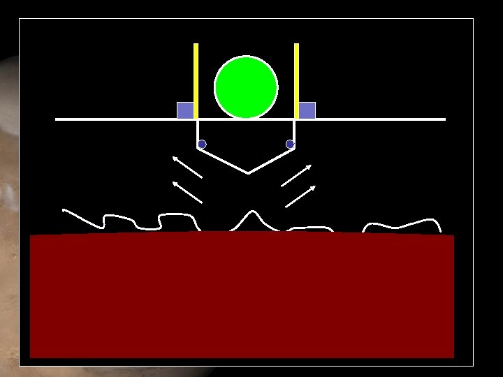
http: //www. lpi. usra. edu/meetings/sixthmars 2003/pdf/3078. pdf Seismological Package (from NETLANDER mission by ESA/NASA) 1. 75 kg
VBB Axis (+BRB) 22 -5 mm, 10 mm × 3 10**-4 -10 Hz, 10**-2 -10 Hz JPL Axis Evacuated Sphere Very Broad Band Seismometer (VBB) ~800 g Micro. Seismometer(SP/NB) 22 -5 mm, 10 mm × 3 10 -100 Hz Resol: ~10**-9 m/(s**2)/HZ**-1/2 ~100 g http: //ganymede. ipgp. jussieu. fr/GB/projects/netlander/sismo/
Data Return Strategy
TELECOM Hardware A. Earth to Mars Transit • • Redundant X-band Trans/Rec 1 medium gain and 2 low gain antennae B. Entry, Decent, and Landing • • • Electralite Trans/Rec UHF, non-directional monopole Comms with MTO C. Landers • • • Electralite Trans/Rec UHF, non-directional monopole Comms with MTO
SDST NESS CARRIER X-Band Downconverter command data to S/C CDS Processor TWTA telemetry data from S/C CDS X-band MGA Horn HYB Diplexer X-band 35 W, RF X-Band Exciter HYB CXS WGTS TWTA Ka-Band Exciter X-band 35 W, RF X-band LGA SDST X-band LGA X-Band Exciter Processor command data to S/C CDS telemetry data from S/C CDS WGTS NESS EDL Ka-Band Exciter UHF Monopole X-Band Downconverter NESS LANDER Electra Lite D I P L cxs
TELECOM Systems • Optimal 128 kbps – Decrease transmit window, maximize data volume transfer – Average ~23 minute link per lander/SOL for 180 Mbits/SOL (avg. transfer capacity 315 Mbits/SOL) – Potential increase to 256 kbps with loss of total data volume received, but decrease in power consumption 11% 14% 58% 38% 17% 18% SOL 1 28% 16% SOL 2 24% 25% 26% 25% Avg 10 SOLS
Ground Systems: DSN Deep Space Network: • • • Launch, track TCMs, cruise Lander deployments (biggest cost) • • 24 -hour coverage for 6 weeks Science operations (relay through MTO) • • Daily (1 -hour) coverage in first month Weekly (1 -hour) coverage for duration
Cruise-Phase Power • A 2 m 2 fixed array powers the carrier – Supplies power to last lander for telecom, TCM’s, etc. – Charges lithium-ion lander batteries prior to separation • During 32 -day separation phase, landers sleep – Timer circuit wakes controller just prior to EDL – EDL is powered by short-term thermal battery – Li-ion battery powers array deployment once landed
Lander Array • Supplies instruments and controller day and night with 23 -minute daily telecom – Daily energy usage ~330 Wh • Landers are identical, so must design for worst-case latitude • Array is non-articulating because diffuse light limits benefit of orienting toward sun
Lander Array Power Estimation daily solar incidence per m 2 during landed mission Orbital state (LS) Minimum solar flux day Latitude • Driving power constraint is minimum solar energy for lander at 30 N at Ls = 270 (approx. 6 months after landing) – 1900 Wh/m 2/sol, 30% power reduction from dust, 27% efficient cells – A 1. 2 m 2 solar array (4 petals) gives a 30% contingency factor
Thermal Design Overview RHU Temp Sensors Mylar Blankets Heaters Thermostat Lander 9 30 7 5 5 EDL 0 30 15 10 20 Carrier 0 60 35 8 16 Need to keep instruments, parachutes, and propulsion tanks heated
Command Data Handling • • Requirements for CDS: • Data volume storage of 180 Mbits per sol for up to 8 days • Data transfer rate to MTO (Mars Telecom Orbiter) at 128 kbps • Data transfer rate between instruments and data storage average of 1 kbps (camera burst rate of 10 Mbps) • Modified I/O card • interface between computer and I/O card • Interface to instruments, power, propulsion, ACS (Attitude and Control Subsystem) elements, telecom, carrier separation interface & state of health to carrier Design assumptions of CDS is rad-tolerant • • • Total dose: 20 -50 krad SEU (Single Event Upset) threshold LET: 20 Me. V/mg/cm 2 SEU error rate: 10 -7 – 10 -8 bits per day Data storage capability (per lander): • 8 Gbits (includes data storage for missed pass) • capable of storing up to 40 sols of data 2 landers will be capable of controlling cruise and EDL (Entry, Descent, and Landing) stages of mission
Attitude Control -- Carrier • Cruise stage – Three-axis attitude control, with control electronics on landers. One lander is used, others are for redundancy. – Eight sun sensors (coarse), for safe mode. – Two star trackers (6 arcsec accuracy) – Two IMUs (inertial measuring unit), drift corrected by star trackers • Lander deployment – Attitude adjustments for lander deployment accurate to within 0. 1°. Each lander is spun up to 2 RPM with a spin table, and popped out using springs.
Attitude Control -- Landers • Three accelerometers to determine: – When to deploy parachute – When the lander impacts Martian surface – Orientation after touchdown ACS Costs • Carrier: – $10, 087, 000 • Lander: – $477, 000 • Total: – $10, 564, 000
Public Engagement
Public Engagement “Today, America has a serious shortage of young people entering the fields of mathematics and science. This critical part of NASA’s Mission is to inspire the next generation of explorers so that our work can go on. This educational mandate is an imperative. ” -- NASA Administrator Sean O’Keefe Making Mars Real - Constructing a virtual experience as “psychologically real as someone’s backyard” Sharing the Adventure - N. E. S. S. - An opportunity for us all to explore.
Public Engagement Education • Formal-Learning experience inside classroom – Nationwide workshops for educators (Teaching Teachers) – Focus on Seismometry and Meteorology mission and science analogs. (K-12, college) – Provide mission related materials to educators for the generation of curriculums that follow national guidelines. (Supporting Teachers) • Informal-Learning experiences outside the classroom – – – Imagine Workshops Science Seminars Museum Partnerships Youth Groups/Community Groups Guest Observer Programs Visualization/Imaging/Audio An opportunity for us all to explore
Public Engagement Outreach • Public Outreach – Name the landers/sites participation – The Mars Insider Program: Daily Updates from N. E. S. S. (climate, weather, and sound) partnership with weather channels and programs – Public presentations (mission scientist and engineers) – Dynamic educational Website – Make-a-seismometer project (Mars vs. My Backyard) An opportunity for us all to explore
Overall Mission Risk Matrix 5 L i k e l i h o o d 4 3 Sys: 1 Tel: 1 Sys: 2 Cos: 1, Ins: 1, Pow: 1, Sci: 1, Sys: 1 Ins: 2, Mis: 1, Pow: 1, Str: 1, Sys: 2 Gro: 1, Pow: 1, Ris: 1, Sys: 3 Ins: 2, Mis: 1, Pow: 1, Sys: 1 EDL: 2, Ins: 3, Mis: 3, Sof: 1, Str: 1, Sys: 2 ACS: 1, Sci: 1, Sys: 3, Tel: 1 2 Ins: 1, Sci: 1 Pow: 1, Sys: 1, The: 2 1 ACS: 1, CDS: 1, Ins: 2, Pro: 2, The: 2 ACS: 1, Pro: 1 ACS: 1, Mis: 1, Sci: 1, Sys: 1, Tel: 1 Mis: 1, Sci: 2, Str: 1, Sys: 3, Tel: 2 ACS: 3, Sci: 2, Sof: 1, Str: 2, Sys: 1 1 2 3 4 5 Impact
Major Risks to Mission Activities • 26 risks have been identified. • 6 of the risks have been determined by many of the systems/disciplines to be critical to the mission. – If don’t land on crushable material because of uncertain landing terrain, then severe damage to lander and loss of data (Impact – 4, Likelihood – 3) • Mitigation: Land in locations where terrain is most understood and fewest elevation changes (Impact - 4, Likelihood - 2) – Single string redundancy on the lander (Impact - 5, Likelihood – 2) • Mitigation: Determine which systems have the lowest reliability and either increase this reliability or add a redundant component (Impact 4, Likelihood - 1) – Seismometer can not take the large g-loads on landing (Impact – 5, Likelihood – 3) • Mitigation: Perform adequate testing to insure that instrument will withstand landing (Impact - 5, Likelihood - 1)
Major Risks to Mission Activities (continued) – Failure to establish seismometer contact with the ground (Impact – 5, Likelihood - 3) • Mitigation: Increase reliability of ground contact mechanism (Impact - 5, Likelihood - 1) – Failure to handover CDS control of cruiser (with landers still attached) if primary control system fails (Impact - 5, Likelihood - 3) • Mitigation: Build into CDS an automatic handover of control to another landers processor if the primary CDS fails (Impact - 4, Likelihood - 2) – Loss of power because of dust build up on the landers systems, such as solar arrays (Impact - 4, Likelihood – 3) • Mitigation: More analysis needed to determine how much this will really effect the instruments
Project Schedule
Project Life Cycle Phase Start Date Pre Phase A Advanced Studies Duration Notes 12+ month instrument tech development Phase A Mission & System Definition 11/14/08 5 months Phase B Preliminary Design 4/16/09 5 months Phase C Design & Build 9/15/10 15 months Descope saved 1 month Phase D Assembly Test & Launch Operations 12/14/10 12 months Descope Saved 1 month Phase E Operations 1/5/12 21 months
Organization Chart NASA Program Office (NPO) Science Team Principal Investigator - Algorithm Development - Science Data Reduction SW - Science Data System - Science Data Processing - Education & Outreach Project Manager JPL Safety & Mission Assurance JPL Mission Design Reqmts. Doc. Flight Sys I/Fs L/V I/Fs - Mission Design Manager JPL -Trajectory and Maneuver Design - Mission Activity Coordination - Mission and Navigation Plans Advisory Board PI, Chair Dean, PI's U. Dir For PFP, JPL VP, S/C IP Business Manager JPL Project Systems Engineer JPL Instrument Manager JPL - Instrument Design - Instrument Fabrication - Instrument I&T Flight System Manager JPL - Spacecraft Subcontracting & Fabrication & Integration - Flight System I&T - Operations Support - Planning - Resource Analysis - Schedule Analysis - Earned Value Mgmt - Procurements Mission Operations Manager JPL - Ground System Development - Flight Operations - NASA Ground Station I/F
Work Breakdown Structure MARS Lander S. S. 2004 -2008 1 WBS Levels 2 Proj Mgmt 01 3 4 NESS Proj Sys Eng 02 Mission Assurance 03 Science 04 Payload Sys 05 Flight Sys 06 Mission Ops Sys 07 Proj Mgmt 01. 01 Proj Sys Eng 02. 01 MA Mgmt 03. 01 Sci Mgmt 04. 01 PS Mgmt 05. 01 FS Mgmt 06. 01 Reserved FS Modules 06. 07 - 06. 10 MOS Mgmt 07. 01 Business Mgmt 01. 02 Mission & Nav Dsgn 02. 02 Sys Safety 03. 02 Sci Implementation 04. 02 PS Sys Eng 05. 02 FS Sys Eng 06. 02 FS Sys Testbeds 06. 11 MOS Sys Eng 07. 02 Risk Mgmt 01. 03 Proj SW Eng 02. 03 Environ Eng 03. 03 Sci Support 04. 03 PS Prod Assur 05. 03 FS Prod Assur 06. 03 FS I&T 06. 12 Gnd Data Sys 07. 03 Review Support 01. 04 eeis 02. 04 Reliability Eng 03. 04 Educ & Pub Outreach 04. 06 PS CC and M&P 05. 04 FS CC and M&P 06. 04 Inst MOS & GDS 07. 04 Facilities 01. 05 Info Sys Eng & Comm 02. 05 Parts Eng 03. 05 Inst 1 05. 05 VBB Seismometer NEtlander FS Module 2 06. 06 (Sys Contract) Operations 07. 05 Reserves 01. RE Config Mgmt 02. 06 QA Eng 03. 06 Inst 2 05. 06 (Contract) Micro Seismometer JPL Planetary Protection 02. 07 SW IV&V 03. 07 Inst 3 05. 07 GEO Phone Commercial Launch Approval Eng 02. 08 Mission Ops Assur 03. 08 Inst 4 05. 08 - 05. 19 MET Pack JPL Launch Syst 08 Launch Services 08. 01 MOS V & V 07. 06 NOTES 01. RE: Includes all Project reserves as a non-WBS item. Launch System Eng 02. 09 Inst 5 05. 20 Pan Cam ASU? Project V&V 02. 10 Common PS HW 05. 31 PS I&T 05. 32 05: Use reserved elements 05. 08 - 05. 19 as needed for additional instruments and 05. 21 - 05. 29 as needed for additional technology payloads. 05. 03 and 06. 03: Top level product assurance elements are used for system contracts providing more than one instrument or flight module 06. 05: Use the WBS elements in 06. 05 as the template for Flight System Modules that are implemented in-house at JPL. 06 Use the WBS elements in 06. 06 as the minimum template for Flight System Modules that are implemented as System Contracts. Add selected WBS elements from 06. 05 as needed for activities performed by JPL. 06. 07 - 06. 10 : Use reserved elements 06. 07 - 06. 10 as needed for addional Flight System Modules including Orbiters, Rovers, etc.
Cost Estimation Process • Cost Chair requests data from all subsystems • The data are the parameters for equations in a cost model developed by Team X specialists using historical data • These data are run through the cost model and tabulated • The process is iterated until all subsystems are satisfied
Cost Assumptions • • Class B mission Cost Dollars are FY 2004 Inflation rate = 3. 1% We assumed a 97% learning curve for the landers and the EDL (Iearning curve equations incorporated into Team X models).
Expected Cost • $572 M Expected Cost • There is no single huge cost driver. The cost is spread roughly evenly among the different subsystems. • The upper estimated bound of the cost is $686 and the lower estimated bound is $515.
Cost Breakdown
Mission Summary • First global network of landers on Mars • Addresses NASA’s exploration goals • Lay foundation forecasting hazards and weather change for human exploration
Thank You • Team X • Co. Co Karpinski and Anita Sohus • JPL employees and facility managers • PSSS