Microgoniophotometer By Team 11541 Sadaf Mackertich Jeffrey Herbert

Microgoniophotometer By: Team 11541 Sadaf Mackertich Jeffrey Herbert Peter Bowlin Lemuel Lebron

Functional Decomposition

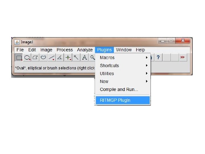
Initialization Process

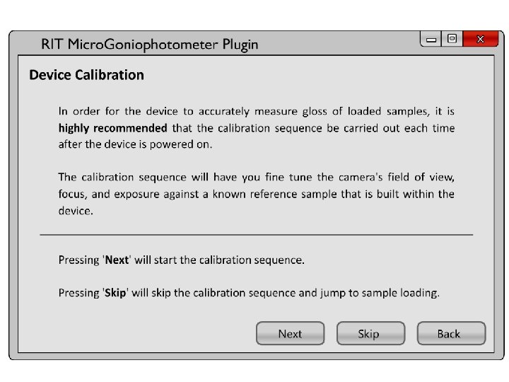
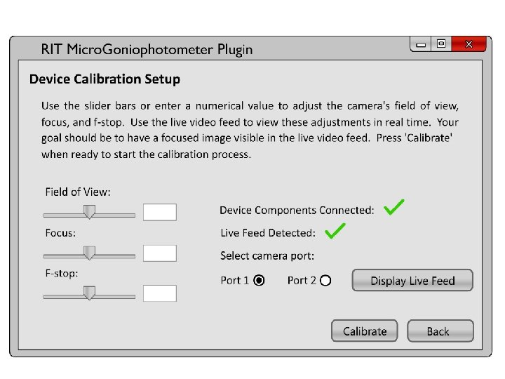
Calibration Process

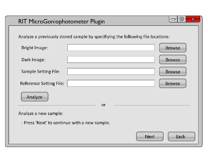
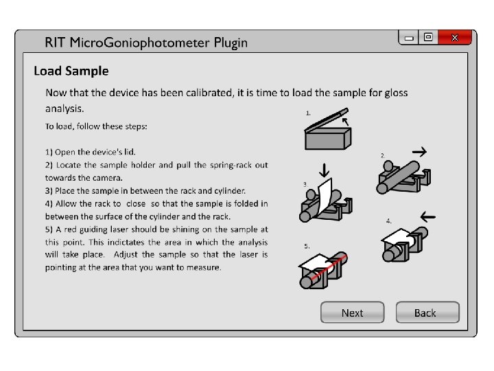
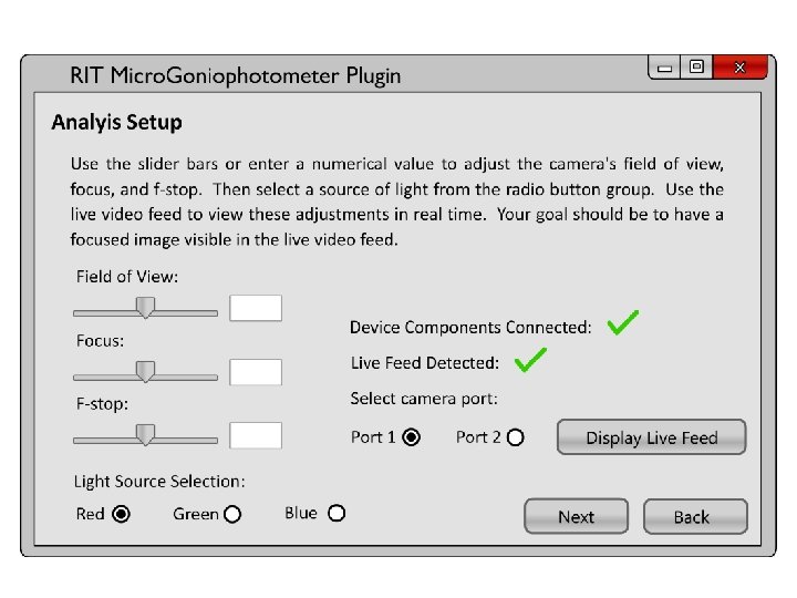
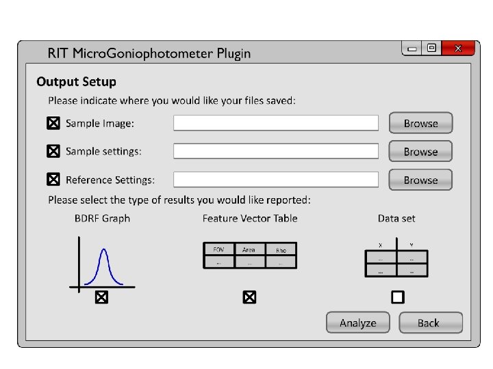
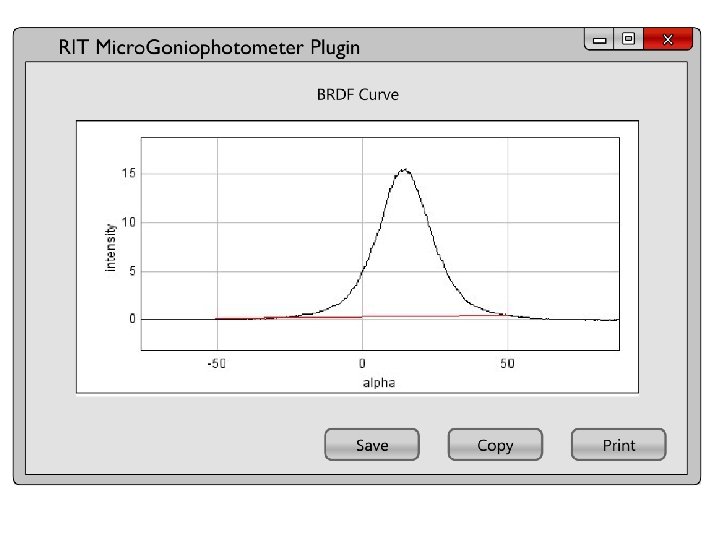
Measurement Process

Customer Needs

Specifications

Complete System

System Components Sample Holder RGB Light Holder Camera Zoom, F-Stop and Focus Polarizing Lens Holder

Sample Holder Balloon View

Feasibility

Sample Holder Exploded Video

Camera Zoom, F-stop and Focus Balloon View
tanΦ Δc=difference between pitch circles Δc = rΘ/2 tanΦ Δc(1 degree) =")
Feasibility S=rΘ S=2(Δc)tanΦ Δc=difference between pitch circles Δc = rΘ/2 tanΦ Δc(1 degree) = 0. 0759 in Max Stress: 6*10^5 Pa FOS: 450

Camera Zoom, F-stop and Focus Exploded Video

Camera Zoom, F-stop and Focus Video

LED Holder Balloon View

LED Holder Exploded Video

Feasibility

Automated Polarizing Lens Balloon View

Automated Polarizing Lens Video

Light Bar Polarizer Holder Balloon View

Original UML Diagram

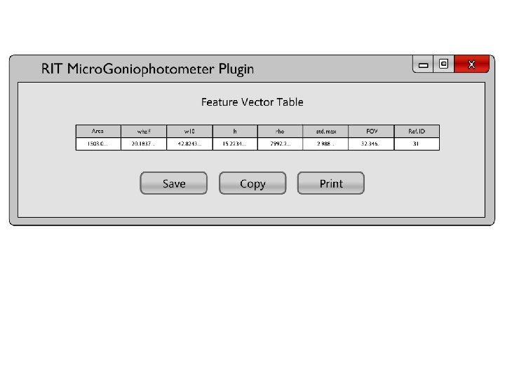
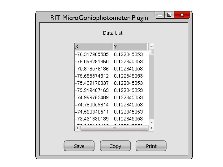
Arney’s Algorithm Previously in Java Math. CAD Results h matc not Does Java Results

Proposed UML Diagram

State Pattern - Increases extendibility of the program by encapsulating different behaviors that a single class will exhibit into external “state” classes - Reduces large clumps of “if…else” blocks and case statements, thus making the code easier to read and understand

Phidget Controller and Listeners - The Phidgets controller already comes with a library of functions to plug into the program - The program will make use of these various Listener interfaces to implement complete User control of the motors, needed in adjusting zoom, focus, and f-stop

Strategy Pattern - The Strategy pattern will again improve the program’s modularity and extendibility by encapsulating the gloss measurement algorithm as a separate. - Future revisions to the program will allow more than one algorithm to be used and selected amongst others

Builder Pattern - The Builder pattern separates data representation from manipulation so as to de-couple as many class dependencies as possible. - It will be used in the program to efficiently implement a means of providing multiple forms of output using the same resulting data


Importance Action to Minimize Risk Owner 2 4 Create precise CAD model Jeff, Sadaf, Pete 2 6 Meet with software professionals Lemuel 1 2 2 Prioritize tasks to limit time loss Sadaf, Pete Flawed design 1 2 2 Test on thinner paper and create a factor of safety. Manually controlled. Jeff Flawed design 2 1 2 Check prototype and modify as necessary Jeff Project will be set back until new camera is purchased Incorrect choice of motors 1 3 3 Create limits Sadaf, Jeff, Pete 1 3 3 Create cover for circuitry Lemuel ID Risk Item Effect Cause Likelihood Severity Risks 1 Interference with motors and housing Fail to automate device Imprecise measurements 2 2 Fail to incorporate all software aspects Cannot deliver one Extremely difficult to simple to use executable program within time file frame 3 3 Parts fail to meet criteria Fail to automate device Incorrect part was ordered or delivered 4 Sample loader destroys samples Function of the device is lost Sample holder fails to keep Cannot acquire a proper sample tight to cylinder measurement surface 5 6 Motors fail to operate under normal conditions 7 Damage to Circuitry Cannot operate device Improper program of circuitry or water damage 8 LED’s burn out Limits test spectrum range Overuse 1 1 1 Create easy to change LED holders and purchase extra. Lemuel 9 Seepage of light from LED holder Improper measurements Flawed design 1 3 3 Place rubber over exposed areas. Jeff, Sadaf, Lemuel, Pete 10 Camera optics break Project cannot continue Improper installation 1 3 3 Purchase a new camera with known F-Stop Jeff, Sadaf, Lemuel, Pete 11 Fail to machine parts correctly Fail to automate machine Incorrect measurements 2 2 4 Purchase cheap, replaceable parts Jeff, Sadaf, Pete

Risk Item Effect 1 RGB Light Holder LED Intensity is too low Low measurement resolution Weak LEDS 1 2 2 2 Gear Ring Countersink breaks through side of ring Ring will not secure onto camera Broken Countersink 2 3 6 3 Polarizing Light Bar Horizontal Position angled Polarized light is not correctly filtered Angled Holder 1 1 1 4 Polarizing Lens Existing polarizing lens creates disturbance in the image due to Artifacts are generated in the measured images Dirty Polarizing Lens 3 1 3 5 Sample Holder Spring is too strong to be comfortably used Uncomfortable use Too high spring constant 1 1 1 6 Software Math calculations do not produce correct results Outputs incorrect Incorrect programming 3 3 9 Gear Ring Backlash due to offset centers creates error in movement of camera components Movement of camera components is inaccurate Offset centers 2 3 6 7 Cause Importance Sub Function Severity ID Likelihood Updated Risks Action to Minimize Risk Research stronger LEDs that can be ordered with low lead time Order enough stock to increase ring thickness Use adjustable bolts to level horizontal surface in the device Order new polarizing lens and install on existing housing Research springs with lower spring constants with low lead times Rectify the existing Java program with Mathcad code with Jon Arney Create assembly fixture to epoxy pinion gears to motors – research helical gear vendors with low lead times Owner Sadaf Jeff Pete Jeff Lem Jeff

Gantt Chart
- Slides: 44