Microcontroller basics Starting with Arduino Exercise 1 Working

Microcontroller basics Starting with Arduino

Exercise 1 Working with Arduino IDE • Basic electric components • Your first program • Digital input and output • Analog input and output • Interrupts •

Arduino IDE • Download from: http: //arduino. cc/en/Main/Software
 USB port 12")
About Arduino Uno Reset button 14 Digital I/O pins (6 PWM) USB port 12 V input 3. 3 V and 5 V outputs 6 Analog Input pins

Setting up Arduino IDE
")
Structure of an Arduino code int pin = 1; 1. Define Variables void setup() {} 2. Setting up functions void loop() {} 3. Eternal loop Before going to the setup function constant variables should be defined Setup function is run once, when the microcontroller boots up or resets. After setup function the processor moves to run code inside the loop function. Code inside loop function will be run over and over until the microcontroller is shut down. • It’s required to have both setup() and loop() functions in the code
 pin. Mode functions sets")
Arduino C – Basic functions pin. Mode(var 1, var 2) pin. Mode functions sets the mode of given pin. Var 1 is the number of the pin and var 2 is the mode (INPUT, INPUT_PULLUP, OUTPUT) digital. Write(var 1, var 2) digital. Write changes the status of the pin. Var 1 is the number of the pin and var 2 is the status (LOW, HIGH). IMPORTANT TO NOTICE: Depending whether the pin is set as an OUTPUT or INPUT the actual effect of digital. Write() is different • digital. Read(var 1) digital. Read returns the current status (LOW, HIGH) of the pin. Var 1 is the number of the pin.
 Analog. Read returns a 10 -bit")
Arduino C – Basic functions analog. Read(var 1) Analog. Read returns a 10 -bit (by default) value equal to the voltage of the pin relative to the analog reference voltage. analog. Write(var 1, var 2) Analog. Write sets a pin (var 1) to a voltage relative to the analog reference voltage equal to an 8 -bit (by default) value. Changes the resolution of the corresponding function to var 1. analog. Read. Resolution(var 1)/ analog. Write. Resolution(var 1) map(var 1, var 2, var 3, var 4, var 5) Maps the value of var 1 linearly form the range var 2, var 3 to the range of var 4, var 5. Works with negative numbers as well.
 Attaches an")
Arduino C – Basic functions attach. Interrupt(var 1, var 2, var 3) Attaches an interrupt to a pin. Var 1 is determined by digital. Pin. To. Interrupt(pin). Var 2 is the function to be ran. Var 3 is the trigger mode of the interrupt. detach. Interrupt(var 1) Detaches an interrupt. Var 1 is again determined by digital. Pin. To. Interrupt(pin). no. Interrupts() Disables interrupts. Used when you are running time sensitive code for example interrupts() Enables interrupts disabled by no. Interrupts().

Writing your first program Basic blinking LED int led. Pin = 13; //Variable to store the pin number void setup() { pin. Mode(led. Pin, OUTPUT); //set led. Pin as output } void loop() { digital. Write(led. Pin, HIGH); //LED ON delay(1000); //Wait 1000 ms (=0, 1 s) digital. Write(led. Pin, LOW); //LED OFF delay(1000); //Wait 1000 ms (=1 s) }

Uploading the program 1. Click Verify The program is checked 1. 2. Click Upload The program is uploaded to the Arduino m. Cu board 2.

Breadboard Terminals with blue and red lines are called power busses and are connected together horizontally. Terminals in the middle are connected together vertically. The gap in the middle separates the two sides.

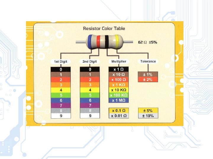
Basic Components Passive components Active components Resistor LED Capacitor Transistor Push button Integrated circuit (IC) Inductor

Example 1 – Push Button Reading digital input
 byte led. Pin =")
Example 1 - Polling Reading digital input (Using push button) byte led. Pin = 13; byte button. Pin = 2; void setup() { pin. Mode(led. Pin, OUTPUT); digital. Write(led. Pin, LOW); //set led. Pin off as default pin. Mode(button. Pin, INPUT); //set button. Pin as input digital. Write(button. Pin, HIGH); //set the default state of the pin to HIGH (+5 V) } void loop() { if(digital. Read(button. Pin) == LOW) { digital. Write(led. Pin, HIGH); //LED ON } else { digital. Write(led. Pin, LOW); //LED OFF } }

Example 1 - Interrupt Using an interrupt for the same job byte led. Pin = 13; byte button. Pin = 2; bool led. State = 0; void switch. LED() { led. State = !led. State; digital. Write(led. Pin, led. State); } void setup() { pin. Mode(led. Pin, OUTPUT); digital. Write(led. Pin, LOW); //set led. Pin off as default pin. Mode(button. Pin, INPUT_PULLUP); //turn on the internal pullup attach. Interrupt(digital. Pin. To. Interrupt(button. Pin), switch. LED, CHANGE); //creates the interrupt } void loop() { //waiting for interrupt }
. Even so you")
• Microcontrollers typically operate on low voltages (0 -5 V). Even so you must be careful when connecting devices. • Know the electrical limits of the microcontroller: Uno can handle max 5 V/40 m. A per I/O pin • Always double check the wiring! If you see smoke it’s already too late!

P=U*I M U=R*I •
 • Basic terms • Duty cycle = Pulse Width /")
PWM (Pulse Width Modulation) • Basic terms • Duty cycle = Pulse Width / Wave Period

Duty cycle • 100 % • 75 % • 50 % • 25 % • 0 % ←Ideal Square Wave

PWM Applications • • • Servomotor angle control DC motor speed control LED Dimming Audio generation Digitally generating analog voltages (requires filtering)
 •")
PWM with Uno • Total of 6 pins with PWM capability (~ symbol) • PWM frequency – Pins 5 & 6: default: 980 Hz ~1 k. Hz (62. 5 k. Hz base with 64 as prescaler) – Pins 3, 9, 10, 11: default 490 Hz ~0. 5 k. Hz (31. 25 k. Hz base with 64 as prescaler) • Can be adjusted (30 Hz-62. 5 k. Hz) with set. Pwm. Frequency(); http: //playground. arduino. cc/Code/Pwm. Frequency CAUTION: Affects the delay() millis() and Servo functions

Example 2 – Control PWM LED Using an analog input to control a PWM LED Longer pin

Example 2 Analog I/O Potentiometer controlled PWM LED int led. Pin = 3; //Variable to store the pin number int pot. Pin = A 0; //Variable to store the pin number void setup() { pin. Mode(led. Pin, OUTPUT); //set led. Pin as output pin. Mode(pot. Pin, INPUT); //set pot. Pin as input } void loop() { int pot. Value = analog. Read(pot. Pin); //Read the value of the potentiometer int led. Value = map(pot. Value, 0, 1023, 0, 255); //map to correct range analog. Write(led. Pin, led. Value); //Read the value of the potentiometer delay(10); //To run the loop ~100 times a second }

In the next exercise • USB communication • Sensors
- Slides: 26