Measuring Pavement Thickness Nondestructively using Pulse Induction Technology

- Slides: 32
Measuring Pavement Thickness Nondestructively using Pulse Induction Technology Current Agency Practices TRB 2019 - Session 1400 Quality Assurance in Construction and Smart Technology Jagan Gudimettla, P. E. ATI Inc (Consultant to FHWA) Office of Preconstruction, Construction, and Pavements
Acknowledgments Ø Todd Hanson (Iowa DOT) Ø Kevin Jones (Iowa DOT) Ø Chad Hayes (Wisconsin DOT) Ø Robert Golish (Minnesota DOT) Ø Gregory Johnson (Minnesota DOT) Ø Richard Howell (Minnesota DOT)
Outline Ø Pavement Thickness Ø Pulse Induction Method Ø State DOTs Experiences Ø Concrete Pavement Thickness Ø Asphalt Pavement Thickness Ø Current State of Practice Ø Summary
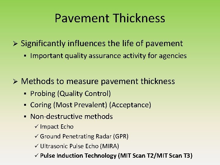
Pavement Thickness Ø Significantly influences the life of pavement § Ø Important quality assurance activity for agencies Methods to measure pavement thickness Probing (Quality Control) § Coring (Most Prevalent) (Acceptance) § Non-destructive methods § ü Impact Echo ü Ground Penetrating Radar (GPR) ü Ultrasonic Pulse Echo (MIRA) ü Pulse Induction Technology (MIT Scan T 2/MIT Scan T 3)
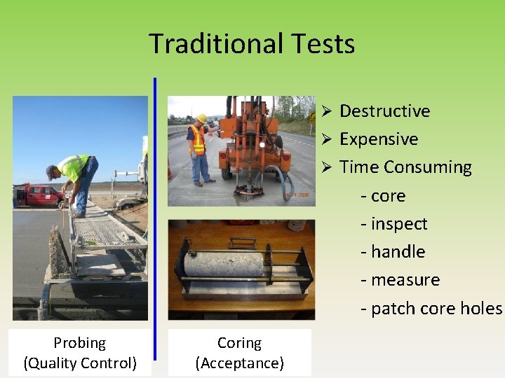
Traditional Tests Destructive Ø Expensive Ø Time Consuming - core - inspect - handle - measure - patch core holes Ø Probing (Quality Control) Coring (Acceptance)
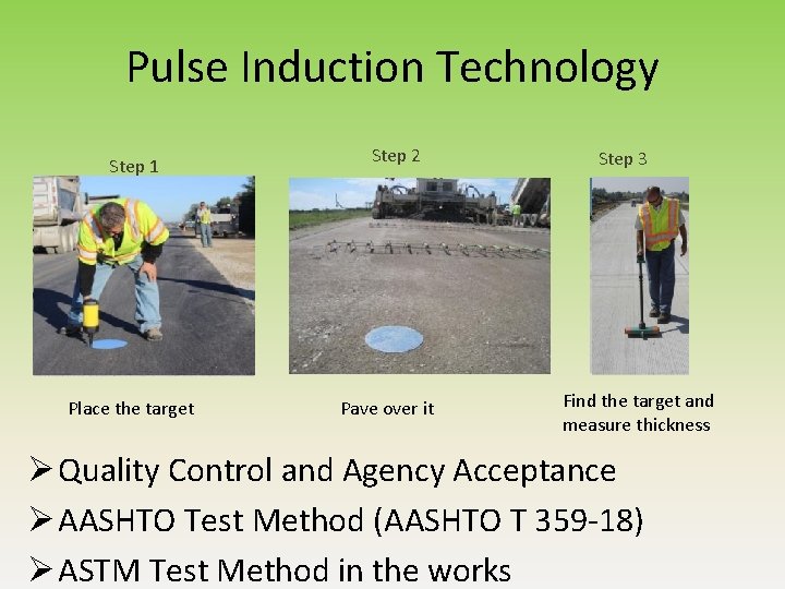
Pulse Induction Technology Step 1 Place the target Step 2 Pave over it Step 3 Find the target and measure thickness Ø Quality Control and Agency Acceptance Ø AASHTO Test Method (AASHTO T 359 -18) Ø ASTM Test Method in the works
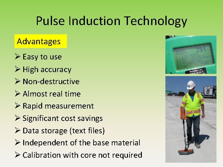
Pulse Induction Technology Advantages Ø Easy to use Ø High accuracy Ø Non-destructive Ø Almost real time Ø Rapid measurement Ø Significant cost savings Ø Data storage (text files) Ø Independent of the base material Ø Calibration with core not required
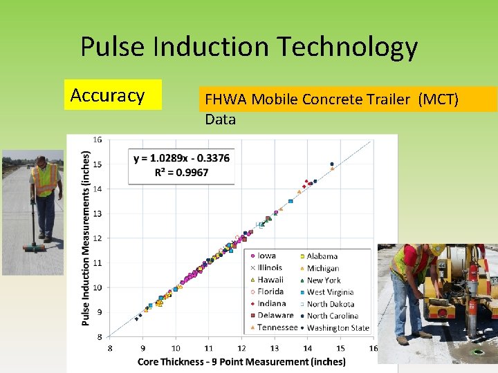
Pulse Induction Technology Accuracy FHWA Mobile Concrete Trailer (MCT) Data 8
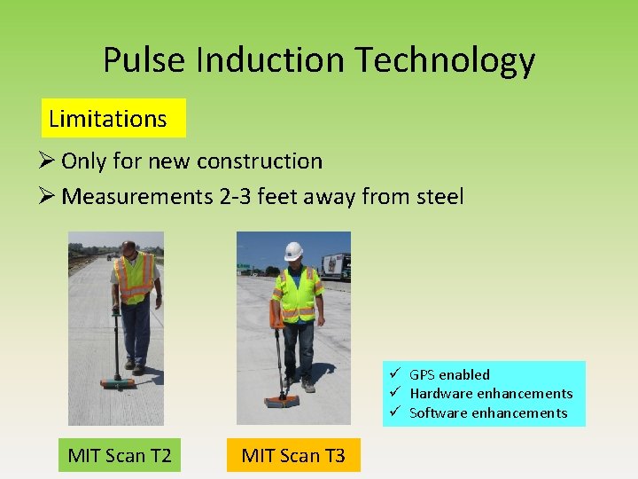
Pulse Induction Technology Limitations Ø Only for new construction Ø Measurements 2 -3 feet away from steel ü GPS enabled ü Hardware enhancements ü Software enhancements MIT Scan T 2 MIT Scan T 3
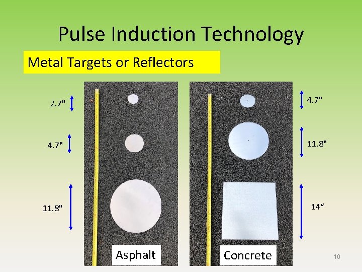
Pulse Induction Technology Metal Targets or Reflectors 2. 7" 4. 7" 11. 8" 14“ Asphalt Concrete 10
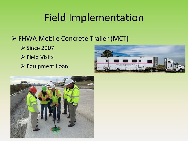
Field Implementation Ø FHWA Mobile Concrete Trailer (MCT) Ø Since 2007 Ø Field Visits Ø Equipment Loan
Iowa DOT Timeline Ø Technology introduced (Spring 2008) Ø Equipment Loan (Fall 2008) Ø Evaluated the technology on two projects (2009) Ø Trial Specification – four projects (2010) Ø Full Specification (2011) Ø Purchased several devices for each of their 6 districts Ø Worked with MCT staff to develop an AASHTO Test Method (2014 -2015)
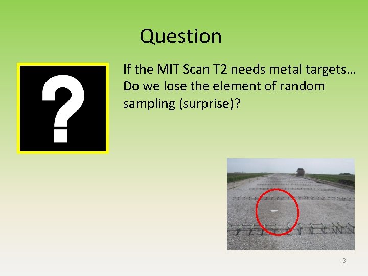
Question If the MIT Scan T 2 needs metal targets… Do we lose the element of random sampling (surprise)? 13
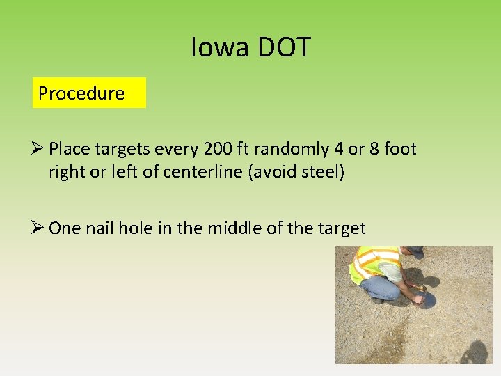
Iowa DOT Procedure Ø Place targets every 200 ft randomly 4 or 8 foot right or left of centerline (avoid steel) Ø One nail hole in the middle of the target
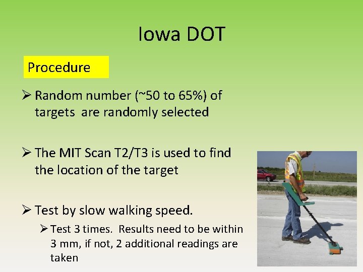
Iowa DOT Procedure Ø Random number (~50 to 65%) of targets are randomly selected Ø The MIT Scan T 2/T 3 is used to find the location of the target Ø Test by slow walking speed. Ø Test 3 times. Results need to be within 3 mm, if not, 2 additional readings are taken
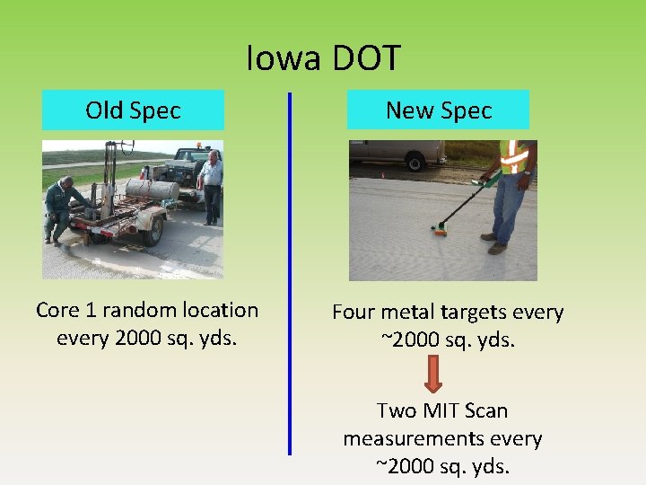
Iowa DOT Old Spec Core 1 random location every 2000 sq. yds. New Spec Four metal targets every ~2000 sq. yds. Two MIT Scan measurements every ~2000 sq. yds.
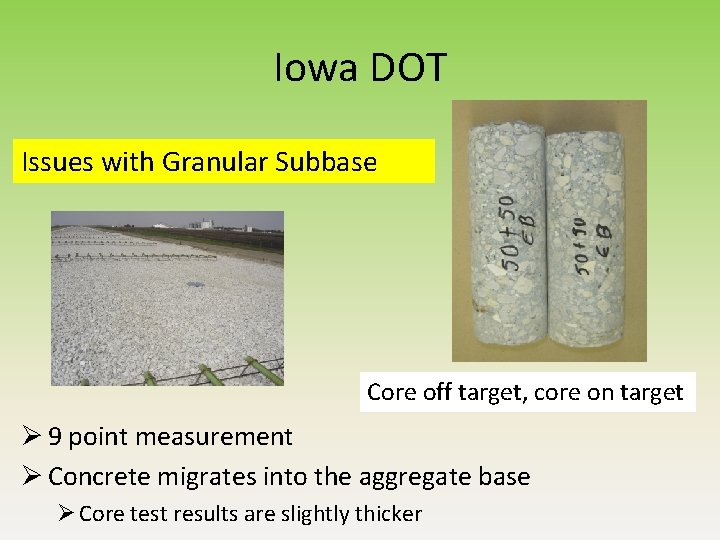
Iowa DOT Issues with Granular Subbase Core off target, core on target Ø 9 point measurement Ø Concrete migrates into the aggregate base Ø Core test results are slightly thicker
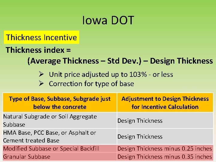
Iowa DOT Thickness Incentive Thickness index = (Average Thickness – Std Dev. ) – Design Thickness Ø Unit price adjusted up to 103% - or less Ø Correction for type of base Type of Base, Subbase, Subgrade just below the concrete Natural Subgrade or Soil Aggregate Subbase HMA Base, PCC Base, or Asphalt or Cement treated Base Modified Subbase or Special Backfill Granular Subbase Adjustment to Design Thickness for Incentive Calculation Design Thickness minus 0. 25 inches Design Thickness minus 0. 35 inches
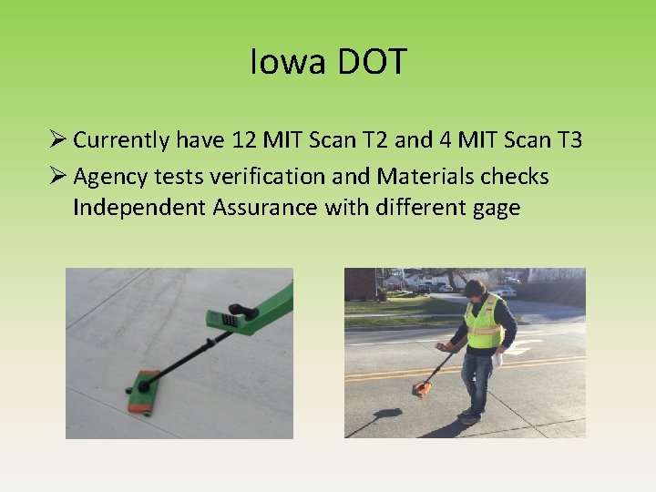
Iowa DOT Ø Currently have 12 MIT Scan T 2 and 4 MIT Scan T 3 Ø Agency tests verification and Materials checks Independent Assurance with different gage
Minnesota DOT Timeline Ø Since 2013 Ø Dowel baskets and tie steel Ø Evaluated for thickness in 2015 and 2016: 9 pilot projects Ø Select projects in 2017 and 2018 Ø Contractor request for using the T 2, no cost supplemental Ø Starting in 2019 (Special Provision) all projects Ø Concrete overlay of an existing asphalt pavement Ø Concrete placed directly on the grade Ø Not used on UBOL Ø Due to steel in the existing concrete
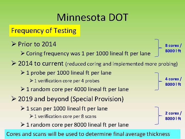
Minnesota DOT Frequency of Testing Ø Prior to 2014 Ø Coring frequency was 1 per 1000 lineal ft per lane 8 cores / 8000 l ft Ø 2014 to current (reduced coring and implemented more probing) Ø 1 probe per 1000 lineal ft per lane Ø 1 verification core per 4 probes Ø 1 random core per 4000 lineal ft per lane 4 cores / 8000 l ft Ø 2019 and beyond (Special Provision) Ø 1 scan per 1000 lineal ft per lane Ø 1 verification core per 8 scans 2 cores / 8000 l ft Ø 1 random core per 8000 lineal ft per lane Cores and scans will be used to determine final average thickness
Wisconsin DOT Timeline Ø Started using Thickness for Acceptance Ø 2017 Ø Ownership Ø Paving Contractors 22
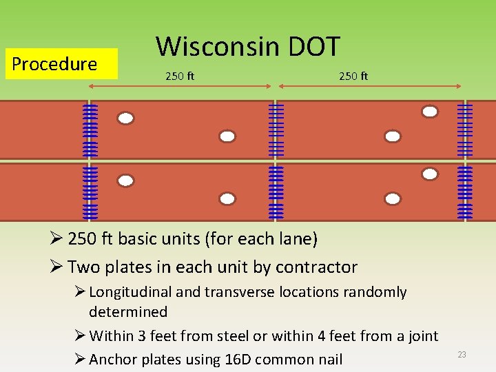
Procedure Wisconsin DOT 250 ft Ø 250 ft basic units (for each lane) Ø Two plates in each unit by contractor Ø Longitudinal and transverse locations randomly determined Ø Within 3 feet from steel or within 4 feet from a joint Ø Anchor plates using 16 D common nail 23
Wisconsin DOT Procedure Ø The department will measure thickness at one random location in each unit Ø If the initial measurement falls within the 80 to 50 percent pay range, the department will measure at the second plate in that unit and average the results to determine pay adjustments 24
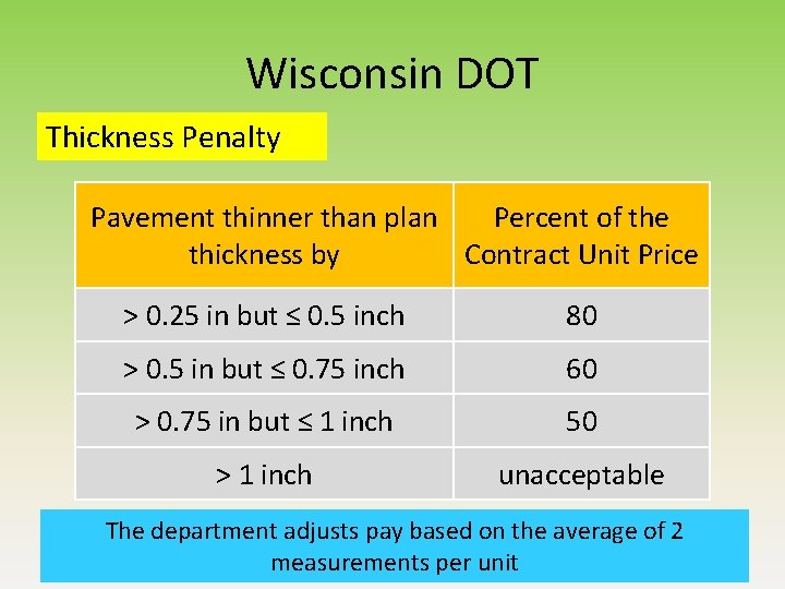
Wisconsin DOT Thickness Penalty Pavement thinner than plan Percent of the thickness by Contract Unit Price > 0. 25 in but ≤ 0. 5 inch 80 > 0. 5 in but ≤ 0. 75 inch 60 > 0. 75 in but ≤ 1 inch 50 > 1 inch unacceptable The department adjusts pay based on the average of 2 measurements per unit 25
What about Asphalt Pavements? Ø Tonnage (asphalt) versus Sq. Yards (concrete) Ø Cores for density purposes (asphalt) Minnesota DOT Experience Ø West Central district uses a pay item of square yard inch (SYI) for asphalt Ø Personnel Issue Ø Weight tickets - Fewer agency folks in the field Ø Additional cores are taken (above the normal density cores) to verify pavement thickness
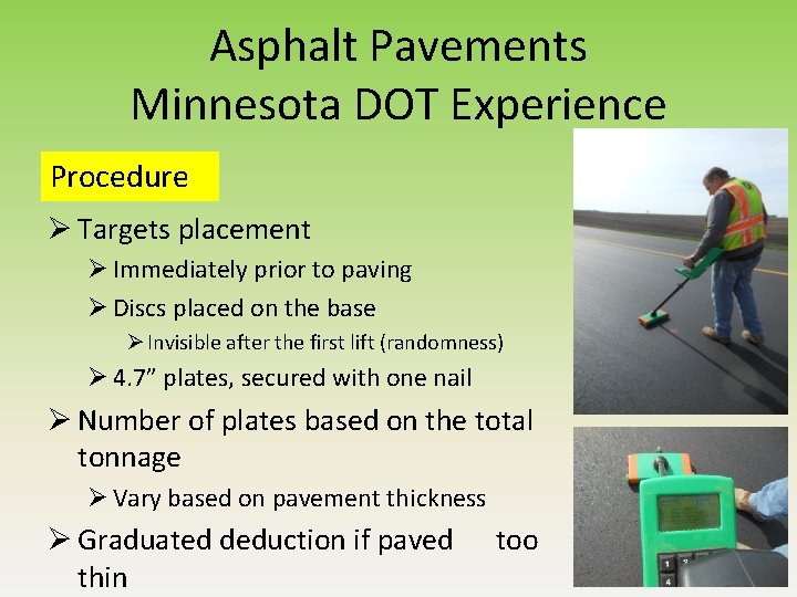
Asphalt Pavements Minnesota DOT Experience Procedure Ø Targets placement Ø Immediately prior to paving Ø Discs placed on the base Ø Invisible after the first lift (randomness) Ø 4. 7” plates, secured with one nail Ø Number of plates based on the total tonnage Ø Vary based on pavement thickness Ø Graduated deduction if paved thin too
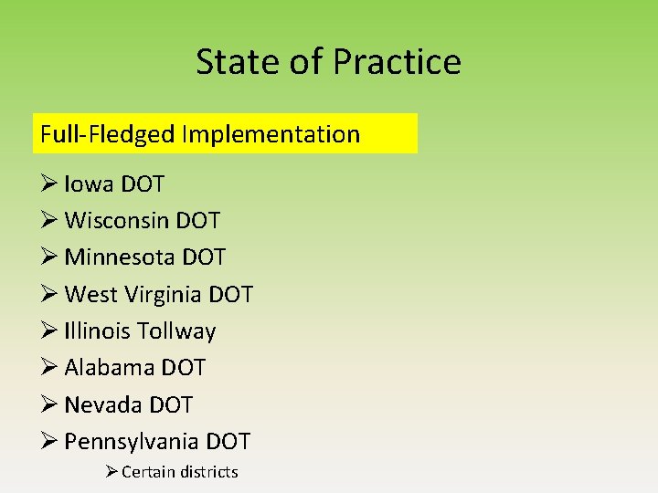
State of Practice Full-Fledged Implementation Ø Iowa DOT Ø Wisconsin DOT Ø Minnesota DOT Ø West Virginia DOT Ø Illinois Tollway Ø Alabama DOT Ø Nevada DOT Ø Pennsylvania DOT Ø Certain districts
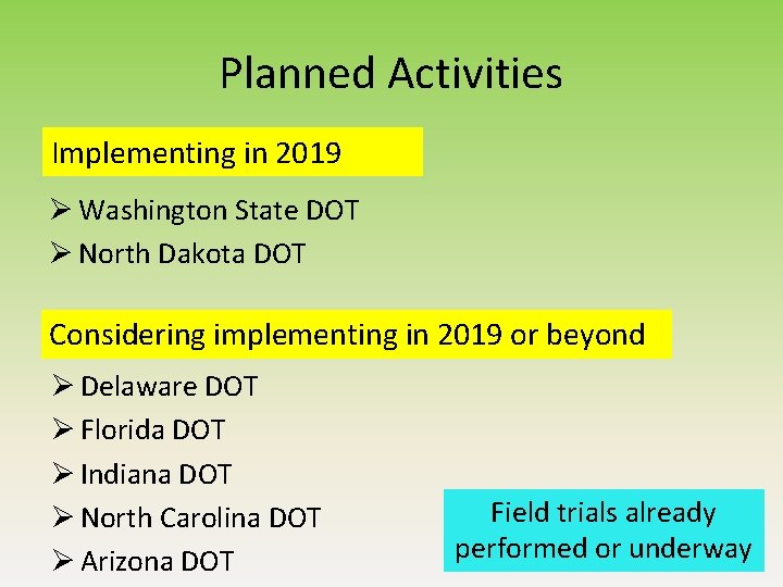
Planned Activities Implementing in 2019 Ø Washington State DOT Ø North Dakota DOT Considering implementing in 2019 or beyond Ø Delaware DOT Ø Florida DOT Ø Indiana DOT Ø North Carolina DOT Ø Arizona DOT Field trials already performed or underway
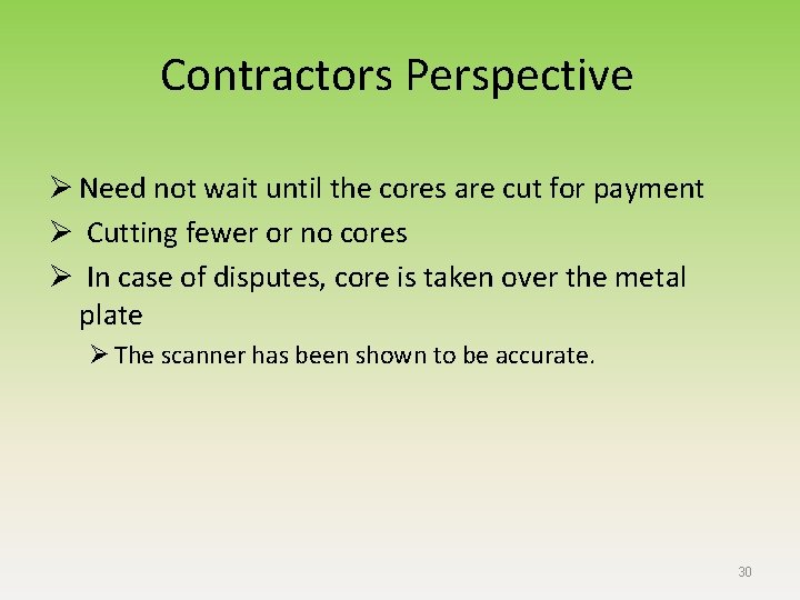
Contractors Perspective Ø Need not wait until the cores are cut for payment Ø Cutting fewer or no cores Ø In case of disputes, core is taken over the metal plate Ø The scanner has been shown to be accurate. 30
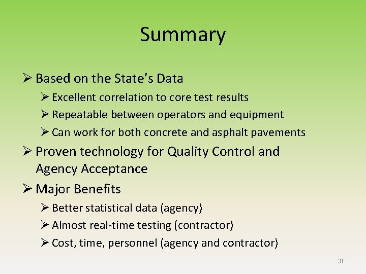
Summary Ø Based on the State’s Data Ø Excellent correlation to core test results Ø Repeatable between operators and equipment Ø Can work for both concrete and asphalt pavements Ø Proven technology for Quality Control and Agency Acceptance Ø Major Benefits Ø Better statistical data (agency) Ø Almost real-time testing (contractor) Ø Cost, time, personnel (agency and contractor) 31
Questions ? ? ? Contact info: Jagan. m. Gudimettla. ctr@dot. gov 202 -366 -1335