Floor Plans l l l Floor plans are


- Slides: 28
Floor Plans l l l Floor plans are the central or core drawings of any set of CD’s. They not only contain a tremendous amount of information for consultants and trades people, they also contain many cross-references to other parts of the documents. Because they play a critical role within the CD set, floor plans are generally the first drawing to be prepared. The floor plan is actually a horizontal section at about 3 feet above the floor.
Floor Plans – General Information Floor plans are usually drawn at 1/16”, 1/8” or ¼” scale. Typically ¼” is used for enlarged floor plans, but is sometimes used for small buildings, thereby eliminating the enlarged drawing. l Locate above right/center of the sheet with NORTH pointing up or to the right. l When drafting the first floor plan you should include major site elements adjacent to the building. This helps tie the site and floor plan together. l Also when drafting an upper level with a roof below you should indicate it with a solid line. l
Dimensioning-review
Dimensioning-rev
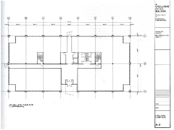
Phase 1 – Getting Started The first phase of drawing the floor plan requires a tremendous amount of work. The goal during this phase is to get as much of the general construction information as possible drawn onto the sheet. This will enable other sheets in the set of construction documents to be started. It will also provide a basis for beginning more detailed conversations with the project consultants. l Structural consultants will be particularly interested in the spans of major structural members as well as the locations of columns. l Mechanical consultants will be interested in such items as glass locations, plumbing stacks, and final building orientation. l
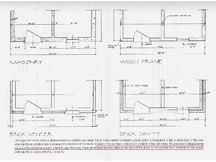
Phase 1 – Getting Started The Phase I drawing shows the earliest stage of this information. The drawing requires that certain assumptions be made. l Although you would not start the partition types or wall sections for the document set during Phase I, assumptions are often made about the construction techniques that will be used for interior partitions and for exterior walls. l This example assumes that the exterior wall is constructed with 3 -5/8” brick, a lair space, 1/2”sheathing, a 6” structural steel stud, and 5/8” gypsum board. l
Phase 1 - Assumptions have also been made about the location of the exterior wall with relation to the column centerlines. A small amount of contingency space has been left that will allow the columns to change size during structural calculations. l It is not uncommon in documentation to have to revise column sizes to reflect the addition of items that were not previously located on the drawings, such as a rooftop mechanical unit. l In these cases, if the exterior of the wall has been located too tight to the column, a substantial amount of redrawing would have to occur to accommodate the new sizes of the structure. Thus, providing a contingency space may save time in later redrawing. l
Phase 1 - Assumptions l In assumptions about the size of interior partitions, an inch or two is not critical, at this scale, to the graphic quality of the document. l In order to have some starting point, however, toilet room partitions have been drawn here with 6” metal studs, toilet chases as being 1 -6” wide, and all other interior partitions with 3 -5/8” metal studs.
First things First… From a sequencing perspective, it is best first to draw the column centerlines and label the column bubbles when drafting these plans. In so doing, you will establish a reference system that can be used on all other drawings within the set. l Next draft all major dimensions and reference them to the column centerlines, and then draft the preliminary structure. Sizes for structural members can be obtained from the structural consultant or from estimates that you can prepare based on guideline information available from the appropriate trades. l Though these initial sizes may change, any revisions will probably be minor and not require any redrafting because of the small scale of the drawings. l
Completion of Phase 1 l The next items you should draft are the exterior walls and the interior partitions. Information on the location of these walls should be available from the design phase of the project. l Finally, you should give the drawing its title and scale and properly fill in the title block information.
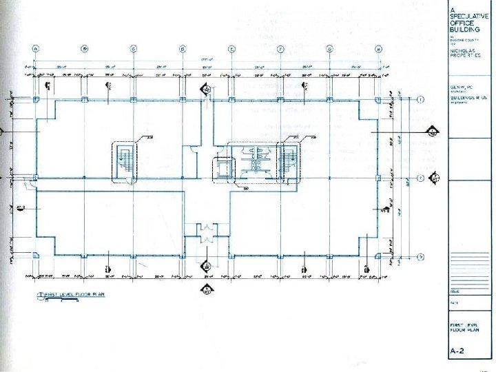
Phase 2 l l l The second phase of the floor plans documentation reflects the addition of cross-referencing. Building elevations, building sections, wall sections, and enlarged plans are all indicated and referenced. It is important to begin cross-referencing the set of construction documents as early as possible. This helps to tie the set together and thus avoid confusion. Strategies for locating where sections should be cut and which elevations should be drawn are discussed later in the class. More detailed dimensions are added to the drawings at this stage. Note that there will now be three dimension strings on the perimeter of the building. The outermost string gives the overall building dimensions, the middle string the structural bay spaces and the inner string the dimensions of surface articulation.
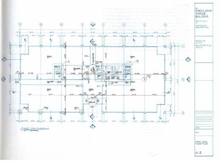
Phase 3 During the third phase room names and numbers are added to the document and doors are given their reference numbers. This allows the schedules to be developed. l During phase three you should also be developing many of the details for the detail sheet or book. l Partitions types, which you should be developing at this point in the process, should have their references added to the plan during this phase along with other miscellaneous details l
Phase 3 continued Phase Ill is also an appropriate time to refine building features that might have been altered or added due to more detailed engineering work. Locations of transformers, telephone boards, electric panels, and so forth should be added and cross referenced. l When you draw a feature such as a telephone board, it is appropriate to reference the proper engineering discipline with a note such as. ‘Telephone Board Reference Electrical. ” l
Phase 3 finished Finally, detailed dimensions are added to the drawings. These dimensions should locate all interior features. l Note that areas that will be drafted as enlarged plans are dimensioned only on their perimeters. More detailed dimensions for these areas will be included on the enlarged plans. l Also note that dimension strings consistently tie into column centerlines. l
Phase 4 The final phase of the floor plan documentation reflects the addition of material indications. Although material indications are not essential in a set of construction documents, their inclusion is helpful and makes the drawings easier for others to understand. l More important during this phase is the addition of miscellaneous notes. Frequently you will have wanted to include an item in the documents, but will not have had time to draw the item. In these cases it is important to at least note the item. In so doing you will have better assurance that the item will not be overlooked during the bid process of the project. l It is also important to check your work at this phase of the documentation. Verify all cross references, detail references, and dimension strings. It is far better to catch mistakes at this point in a project than after a set of documents has gone to bid. l
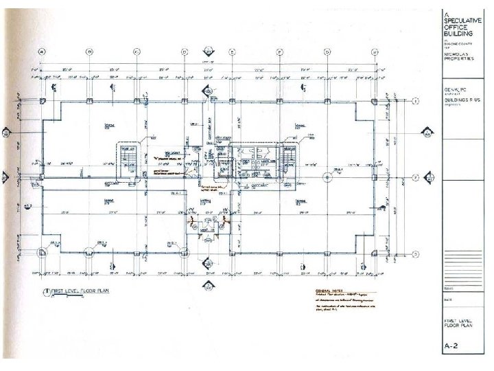
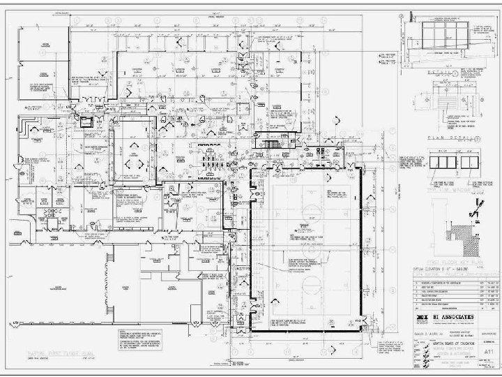
l Completed Floor Plan
l l Block out shape of structure; exterior walls Interior walls positioned with center-lines
l l l Add wall thickness to exterior walls Offset centerline for interior wall thickness Verify door opening widths; leave room for window & door jambs and frames
l Clean-up Stage ll drawing
l l l Add appliances, plumbing fixtures, fireplace Add windows and level changes Check and verify ALL dimensions!!!!
l l l Add all dimensions; note interior walls become thicker at exterior locations Add reference symbols, door, window tags Add electrical information and symbols; CHECK PRINT
l Complete floor plan with labels and notes and references