ME 110 Introduction to CAD Craig R Ronald

- Slides: 37
ME 110 - Introduction to CAD Craig R. Ronald Gavett 208 Harkness 114
Course Format l PTC Creo » Industry recognized leader in mechanical design software. l Focus on solid modeling, detailing and assemblies.
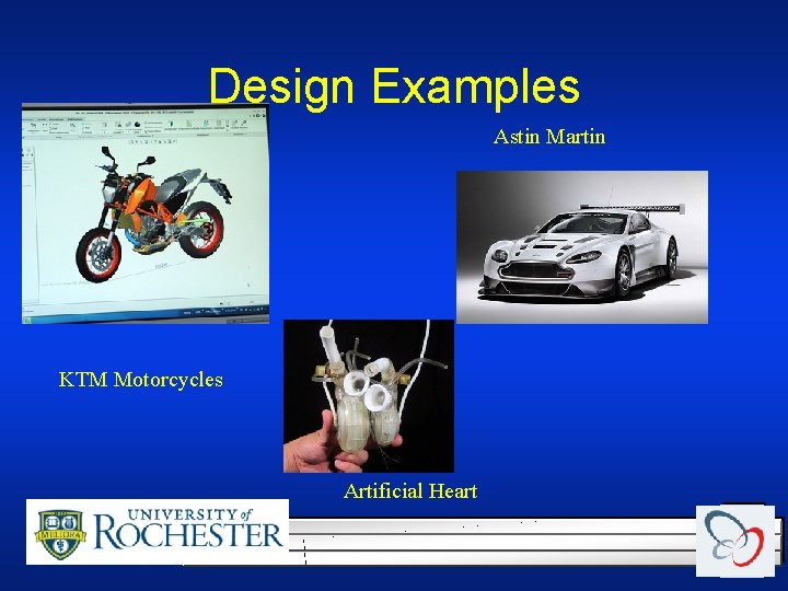
Design Examples Astin Martin KTM Motorcycles Artificial Heart
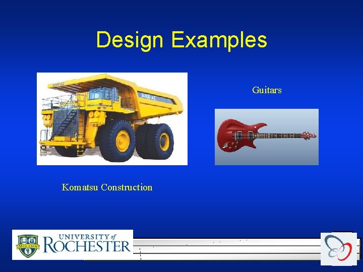
Design Examples Guitars Komatsu Construction
About the Instructor MS Mechanical Engineering U of R 1990 l Taught ME 110 since 1987 l Used PTC Creo since 1997 l
Importance of Course Only a 2 credit course but. . . l Teaches the language of engineering l Skill that is most likely to help job search l
Web Site l http: //www. me. rochester. edu/courses/ME 110 Link is on Blackboard l The web site will be kept up to date l Check frequently! You are responsible for knowing the information on the site. l
Blackboard Log on at: learn. rochester. edu l Assignments l Grades l
Course Outline Phone numbers 259 -6119 Cell(‘til 10 PM) l E-mail: c. ronald@rochester. edu l
Software Access l l l Uof. R Computers in labs Remote access to Uof. R Computers Load Creo on student computers through blackboard. Need to use a three button mouse. DO NOT load software from PTC web site.
Saving Work for Course l Flash Drive – you will need to have a USB flash drive by next lecture. – All HW and test files must be saved – Must be able to show the original files in case of grading disputes. l All course work must be done using school software.
Academic Honesty l l All assignments and activities associated with this course must be performed in accordance with the University of Rochester's Academic Honesty Policy. Suspected violations will be pursued vigorously following the College’s procedures for suspected cases of academic dishonesty. – Collaboration on homework is encouraged – Each student must create and submit their own file while logged onto Windows with their own Net. ID – Sharing files, data, or accounts on homework or tests is prohibited.
Conclusion l. SAVE YOUR WORK l. DON’T CHEAT
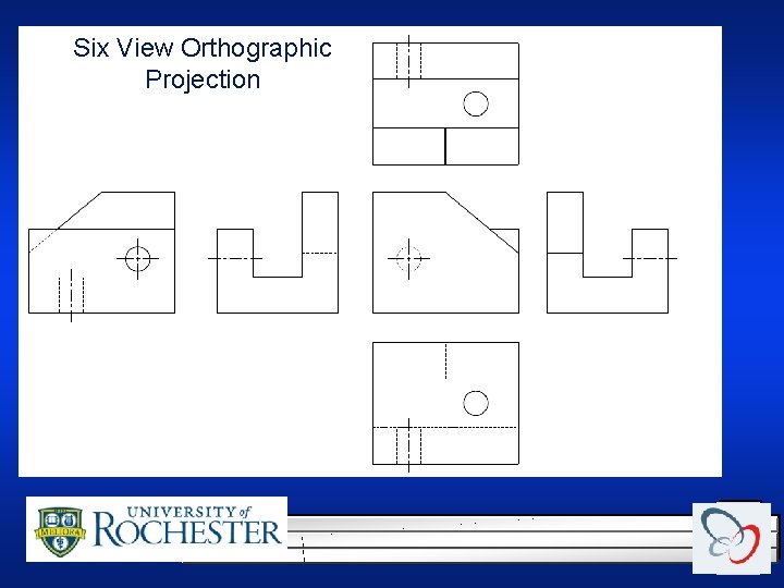
Six View Orthographic Projection
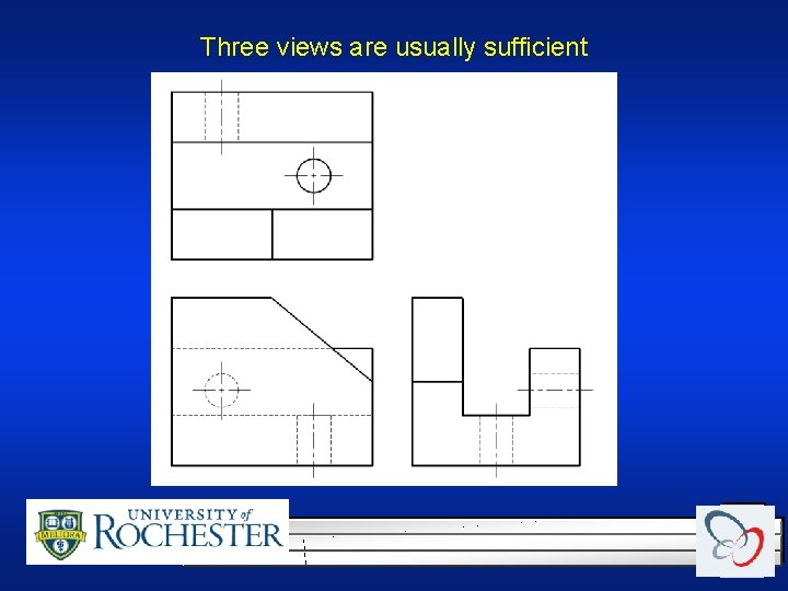
Three views are usually sufficient
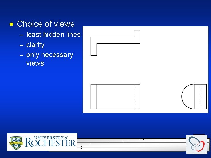
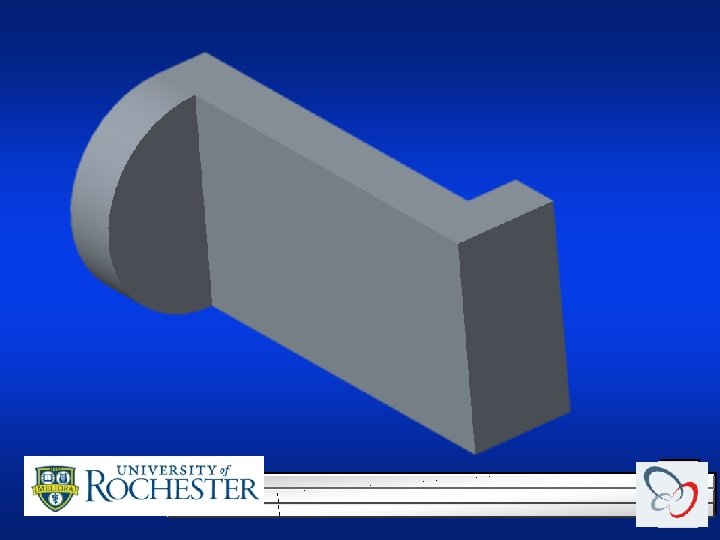
l Choice of views – least hidden lines – clarity – only necessary views
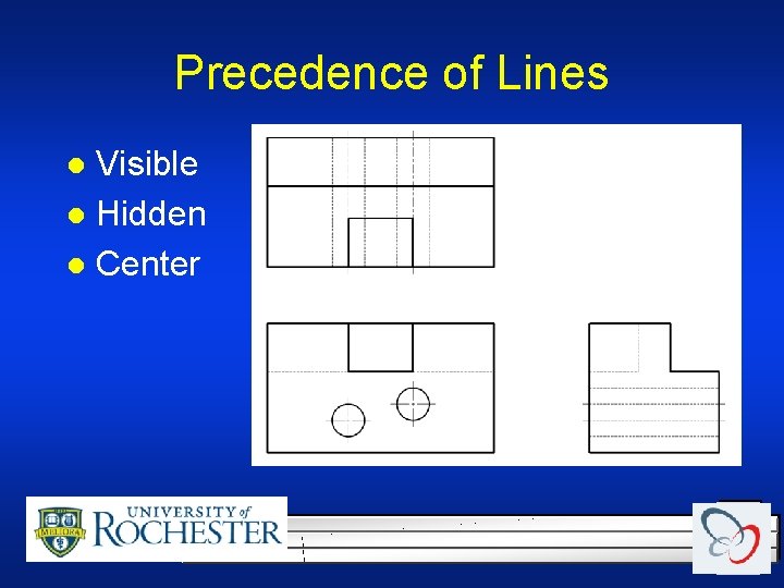
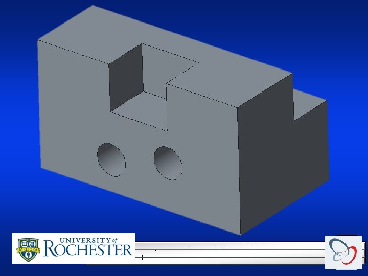
Precedence of Lines Visible l Hidden l Center l
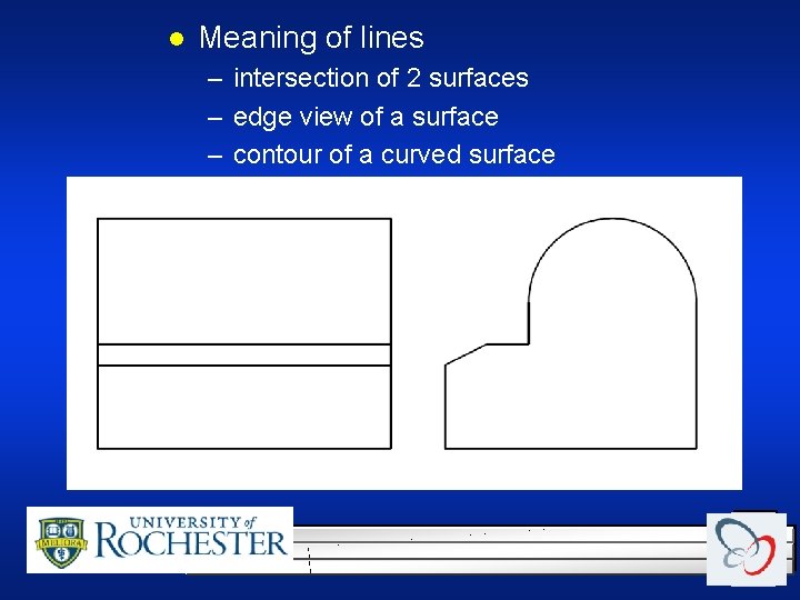
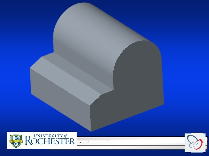
l Meaning of lines – intersection of 2 surfaces – edge view of a surface – contour of a curved surface
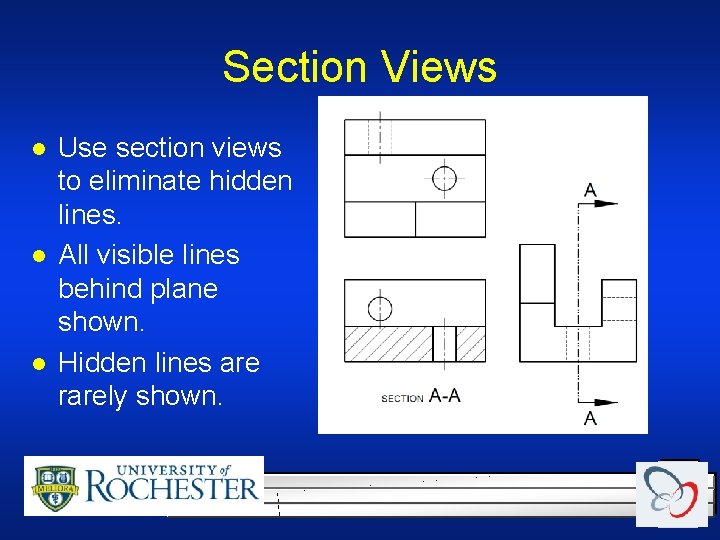
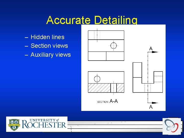
Section Views l l l Use section views to eliminate hidden lines. All visible lines behind plane shown. Hidden lines are rarely shown.
Types of CAD systems l l Wireframe- modeling the curves of the part Surface modeling- Model the surfaces of the part, but without knowledge of material. Solid modeling- full solid representation Parametric Modeling- dimension driven solid modeling.
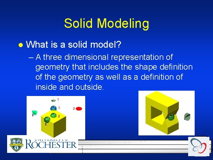
Solid Modeling l What is a solid model? – A three dimensional representation of geometry that includes the shape definition of the geometry as well as a definition of inside and outside.
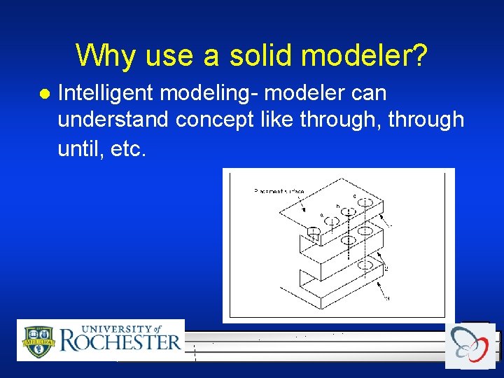
Why use a solid modeler? l Intelligent modeling- modeler can understand concept like through, through until, etc.
Accurate Detailing – Hidden lines – Section views – Auxiliary views
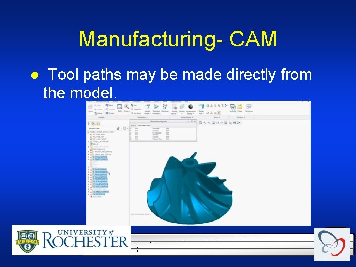
Manufacturing- CAM l Tool paths may be made directly from the model.
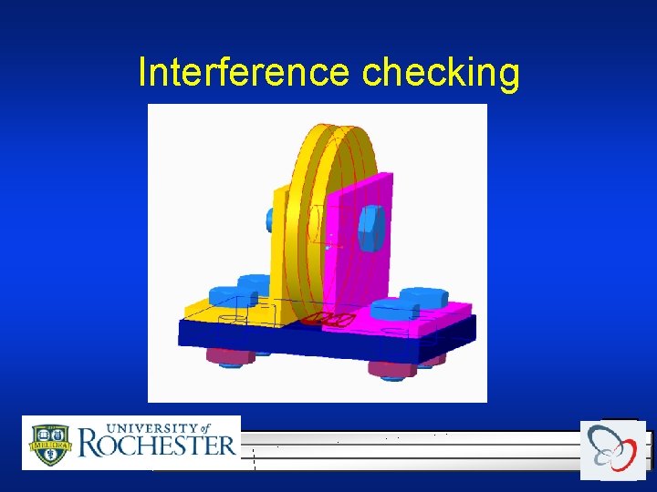
Interference checking
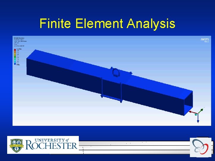
Finite Element Analysis Ability to do Deflection and stress analysis on complex parts/assemblies. l Complex problems are discritized into simple shapes. l
Finite Element Analysis
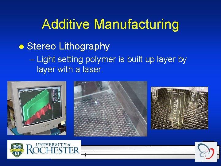
Additive Manufacturing l Stereo Lithography – Light setting polymer is built up layer by layer with a laser.
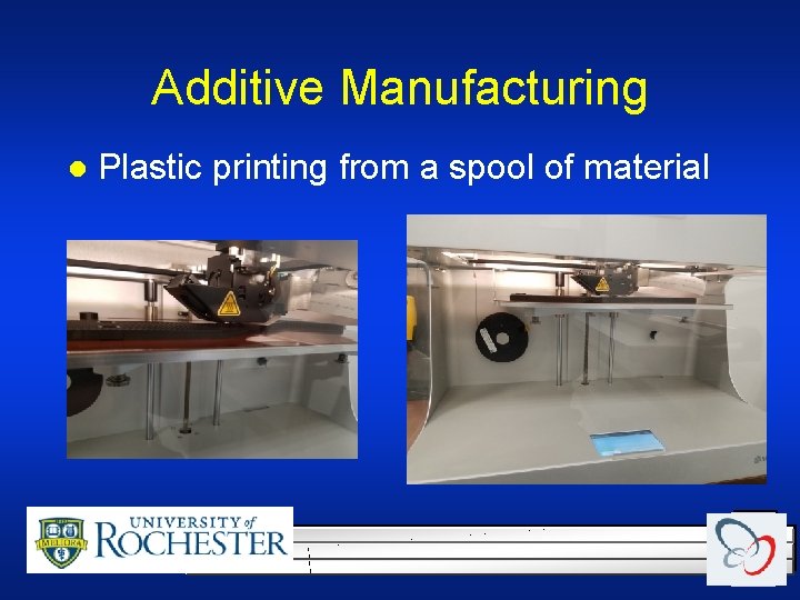
Additive Manufacturing l Plastic printing from a spool of material
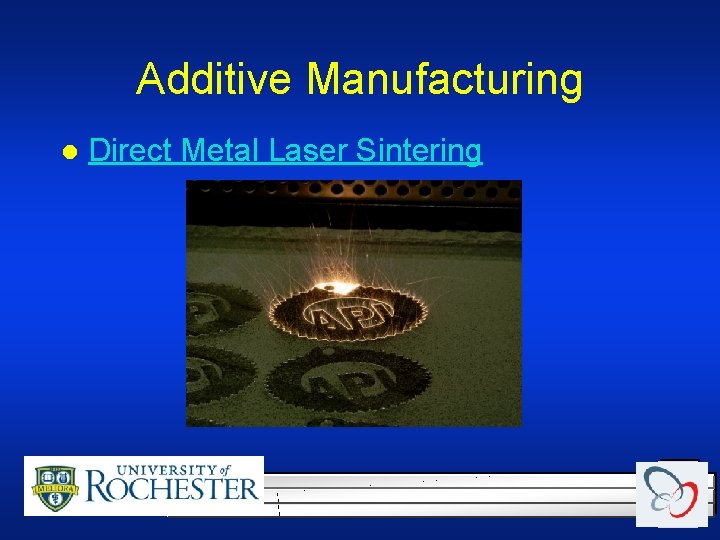
Additive Manufacturing l Direct Metal Laser Sintering
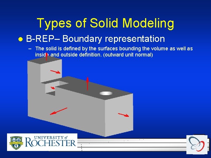
Types of Solid Modeling l B-REP– Boundary representation – The solid is defined by the surfaces bounding the volume as well as inside and outside definition. (outward unit normal)
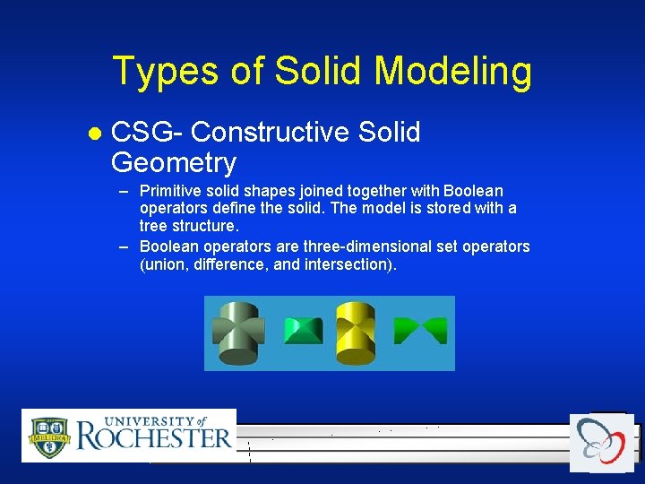
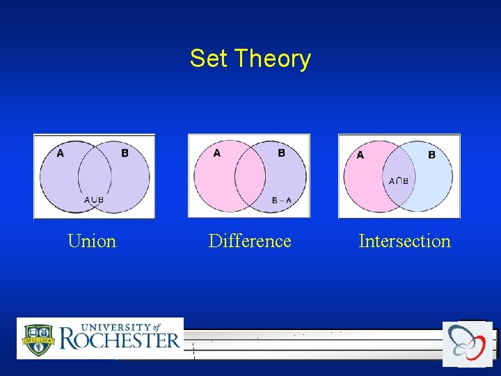
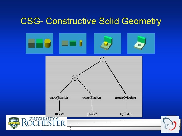
Types of Solid Modeling l CSG- Constructive Solid Geometry – Primitive solid shapes joined together with Boolean operators define the solid. The model is stored with a tree structure. – Boolean operators are three-dimensional set operators (union, difference, and intersection).
Set Theory Union Difference Intersection
CSG- Constructive Solid Geometry