Light and Optics Mirrors and Reflection It wasnt


- Slides: 64
Light and Optics Mirrors and Reflection
• It wasn’t until the early 19 th century that light was theorized to behave as something other than a stream of particles. § Isaac Newton proposed the particle theory of light. ØNewton’s theory was used to explain the reflection and refraction of light. • Christian Huygens proposed the wave theory of light. § His theory could also explain the behavior of light. ØWave theory was not readily accepted – chiefly because it did not jive with other known waves at the time (sound, water, etc. ).
• Thomas Young, Maxwell, and Einstein would later prove the behavior of light as an electromagnetic wave. • The ability of light to behave as both a stream of particles (photons) and as an oscillating electric & magnetic field is known as wave-particle duality.
• When light traveling through one medium encounters a boundary leading into a second medium, some of the light may be reflected. § The light essentially bounces away from the medium. • To study the reflection (and refraction) of light, we will consider the ray approximation: § § Light travels in a straight line path. The path of light is altered upon changing media. Some of the light is reflected from the media. Some of the light passes through the media, and is refracted.
• Light will be represented as straight-line rays in order to study its behavior.
• Specular reflection occurs when light strikes a smooth surface. The reflected rays are parallel to each other. • Diffuse reflection occurs when light strikes a rough surface. The light rays are scattered in many directions.
• The incoming ray of light is the incident ray. • The outgoing ray is the reflected ray. • These two rays make identical angles with a line drawn perpendicular to the reflecting surface – the normal. • In other words: • θi = θr
• We see images when reflected light rays converge in our eyes. • Both mirrors and lenses are able to create images.
• A “real” image is one made from actual light rays converging at a point in the real world. • The image of the candle that appears on the screen is a real image. • Actual rays of light are converging at the screen in order to produce the image. • Real images are always inverted.
• A virtual image is not created from the actual convergence of light rays. • Virtual images are the result of the APPARENT convergence of light rays BEHIND the reflective medium. • The image in the mirror appears to be behind the plane of the mirror. • Virtual Images are always upright, and cannot be projected onto a screen.
• Curved Mirrors have several important features: • The Principal Axis is a line passing through the center of the sphere and attaching to the exact center of the mirror.
• Curved Mirrors have several important features: • The point in the center of the sphere from which the mirror was sliced is known as the center of curvature
• Curved Mirrors have several important features: • The point on the mirror's surface where the principal axis meets the mirror is known as the vertex. • The vertex is the geometric center of the mirror.
• Curved Mirrors have several important features: • The distance from the vertex to the center of curvature is known as the radius of curvature.
• Curved Mirrors have several important features: • At the focal point, light incident towards the mirror and traveling parallel to the principal axis will meet after reflection. • This allows convex mirrors to literally focus many rays of light onto a single point.
• Curved Mirrors have several important features: • Midway between the vertex and the center of curvature lies the focal point. • The distance from the mirror to the focal point is known as the focal length.
• Ray diagrams are used to determine the path of light rays striking a surface. For a concave mirror, there are two rules of reflection: • 1) Any incident ray traveling parallel to the principal axis on the way to the mirror will pass through the focal point upon reflection. • 2) Any incident ray passing through the focal point on the way to the mirror will travel parallel to the principal axis upon reflection.
• The point where the rays meet is the location of the image formed by the reflection. • Only 2 rays are needed to determine image location.
• Pick a point at the top of the image (represented by the arrow). • Draw two incident rays emanating from this point. § One ray should be parallel to the principal axis. § The other should go through the focal point. • Reflect the rays according to the rules for concave mirrors.
• The top of the image appears where the reflected rays cross. Mark this location. • Repeat the process for the bottom of the object. In our example, since the bottom of the object lies on the principal axis, it’s image will also lie on the principal axis.
• L. O. S. T. – Determining Image Characteristics for Concave Mirrors • L: Location of Image § Where is it, in reference to points on the principal axis? • O: Orientation of Image § Inverted or Upright • S: Size of Image § Same, Reduced, or Enlarged • T: Type of Image § Real or Virtual
• Possible Image Locations: • Case 1: the object is located beyond the center of curvature (C) • Case 2: the object is located at the center of curvature (C) • Case 3: the object is located between the center of curvature (C) and the focal point (F) • Case 4: the object is located at the focal point (F) • Case 5: the object is located in front of the focal point (F)
• Case 1: • L: • O: • S: • T: Between C and F Inverted Reduced Real
• Case 2: • L: • O: • S: • T: At C Inverted Same Real
• Case 3: • L: • O: • S: • T: Beyond C Inverted Enlarged Real
• Case 4: • L: • O: • S: • T: No Image X X X
• Case 5: • L: • O: • S: • T: In Front of F Upright Enlarged Virtual
• The Mirror Equation: If I Do, I Di. • The mirror equation gives a quantitative representation of images. • The Magnification Equation gives the change of image size relative to the original image.
Light and Optics Lenses & Refraction
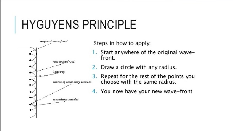
• Refraction is the bending of light as it moves into a new medium. • Dutch Scientist Christian Huygens crafted a way to visualize what happens when a wave reflects or refracts:
• Huygen’s principle helps visualize WHY a light ray changes direction as it passes into a new medium. • From Huygen’s principle, we see that the refraction of a wave as it moves to a new medium causes it to change direction and slow down. • This occurs for all waves, not just light.
• Snell’s Law expresses the relationship between a light wave and the different media through which it passes. n 1 sinθ 1 = n 2 sinθ 2 OR n 1 sinθi = n 2 sinθr • “n” represents the index of refraction for the media. § For air or a vacuum, n = 1. • The angles θi and θr are measured from the normal.
The Normal
• If the angle of incidence reaches the critical angle, the light ray will move parallel to the boundary. § Applying Snell’s Law: n 1 sinθc = n 2 sinθ 2 n 1 sinθc = n 2 sin 90
• If the angle of incidence exceeds the critical angle, Total Internal reflection occurs, and ALL of the light is contained within the medium.
• … Fiber Optic Transmission of Light Fiber Optic Cable
• A lens is a transparent, curved material that refracts light. § A lens is essentially an assembly of prisms. • Lenses are classified based on what happens to the light that passes through.
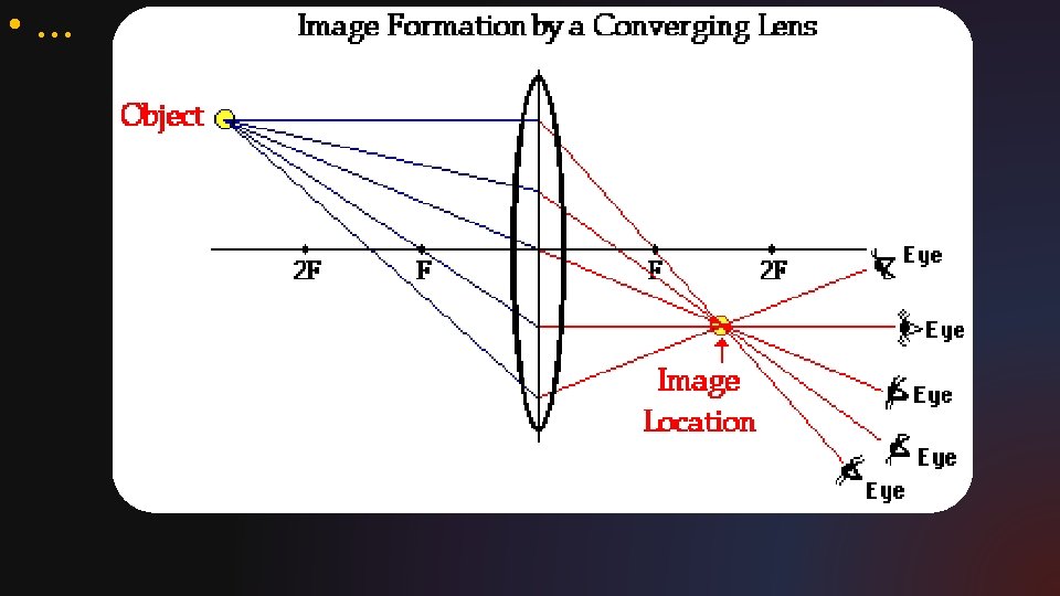
• A convex, or converging lens, causes parallel light rays to converge at a focal point that exists in front of the lens.
• A concave, or diverging lens, causes parallel light rays to diverge in front of the lens. The focal point exists behind the lens.
• The “Thin Lens” Equation:
Rules for Ray Diagrams • Any incident ray traveling parallel to the principal axis of a converging lens will refract through the lens and travel through the focal point on the opposite side of the lens. • Any incident ray traveling through the focal point on the way to the lens will refract through the lens and travel parallel to the principal axis. • An incident ray that passes through the center of the lens will continue in the same direction that it had when it entered the
Rules for Ray Diagrams Diverging Lens • Pick a point on the top of the object and draw three incident rays traveling towards the lens: § Draw one ray so that it travels toward thefocal point on the opposite side. It will strike the lens before reaching the focal point, so stop the ray at the lens. § Draw the second ray parallel to the principal axis. § Draw the third ray through the center of the lens. • Now refract them according to the rules for refraction. See the diagram on the following slide.
Rules for Ray Diagrams Diverging Lens
• di is negative for an inverted image. • hi is negative for an inverted image.
The Properties of Light
• Light can be described in one of two ways: § A beam or stream of “energy packets” called photons. § An “electromagnetic” wave composed of oscillating electric and magnetic fields. § Light exists as both a wave and a beam of photons. This is known as “wave-particle duality”.
• A wave is an “energy transport phenomenon”. § Mechanical waves use a medium to transport energy from one location to another. § Electromagnetic waves do not require a medium to transport energy.
• The crest of the wave is the area of maximum displacement above equilibrium. • The trough is the area of max displacement below equilibrium. § The measure of this displacement is the wave’s amplitude. • The wavelength, λ, is the measure from crest to crest, or trough to trough. § Or any two such points on the wave.
• As a wave travels: § The time it takes for one complete wave (crest and trough) to pass a point is its period, T (s). § The number of waves (or oscillations) that pass a point in ONE SECOND is its frequency, f (1/s, or Hz). § So, the wave period and frequency must be related: Wave Period
• Frequency, period, and wavelength can be used to determine the speed of the wave in its medium. § Recall that v = d/t. § For a wave, the distance is equal to its wavelength. § So, v = λ/T (distance over time) • Because frequency is 1/T, we can say that: Wave Speed • The unit is m/s. • Note that amplitude is not affected by any of these variables.
• Light exhibits s many wave-like properties that are not supported by a “particle only” definition. § Light reflects in the same manner as mechanical waves. § Light refracts (changes velocity) when passing into a new medium. § Light diffracts* around edges and at openings/slits. § Light can cause constructive and destructing interference patterns.
• Wave diffraction occurs when a wave moves around barrier or passes through an opening.
• Thomas Young’s double slit experiment introduced critical evidence to show that light behaves as a wave. § Young set up an experiment in which monochromatic light (light of one color) would shine through two small slits. § If the light behaved as a beam, the light would appear as two slits on the other side.
• If the light behaved as a wave, then it would undergo the process of diffraction. § Diffraction occurs when a wave alters its path when encountering a barrier. • Diffracted light would show a pattern of “spreading beams” that would superimpose & interfere:
• The result of his experiment showed a diffracting pattern of superposition: § Patterns of bright and dim “fringes” appeared on the viewing screen.
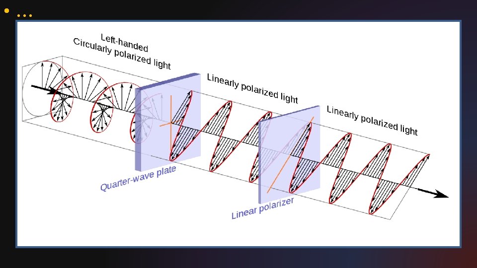
• When the light wave oscillates in multiple planes, it is said to be unpolarized. • Polarization of light occurs when light waves travel in only one plane.
• Polarized light is the result of a filter or material that blocks all but one plane of vibration. • By using two filters, the light can be totally blocked.
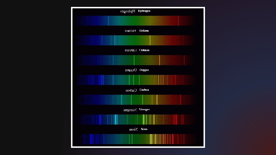
• Electromagnetic waves consist of different forms of “light” that all travel at the same speed through a vacuum. § The speed of EM Radiation is c = 3 x 10⁸ m/s. • EM Waves are categorized by their frequency and wavelength.
• The visible spectrum consists of six colors: ROY G BV • Red light has the longest wavelength, violet the shortest. • Indigo was traditionally listed as a color by Newton, but the widely accepted light spectrum only has six colors.
• Note to self: DON’T LEAVE THIS SLIDE BLANK!