Instructors Power Point for Optoelectronics and Photonics Principles


 Ex = Electric field along x")

 at")


![Exponential Notation Recall that cos = Re[exp(j )] where Re refers to the real](https://slidetodoc.com/presentation_image/28d684090e96ea10d862461b8624c325/image-17.jpg "Exponential Notation Recall that cos = Re[exp(j )] where Re refers to the real")

 = Eocos( t k r + ) A")


,")


 relative permittivity er(LF) and refractive index n.")
 ko 2π/ o")


 The simplest electronic")
 n = n-2(hu)-2")


- Slides: 51
Instructor’s Power Point for Optoelectronics and Photonics: Principles and Practices Second Edition A Complete Course in Power Point Chapter 1 ISBN-10: 0133081753 Second Edition Version 1. 0337 [6 February 2015]
Updates and Corrected Slides Class Demonstrations Class Problems Check author’s website http: //optoelectronics. usask. ca Email errors and corrections to safa. kasap@yahoo. com
Slides on Selected Topics on Optoelectronics may be available at the author website http: //optoelectronics. usask. ca Email errors and corrections to safa. kasap@yahoo. com
PEARSON Copyright Information and Permission: Part II This Power Point presentation is a copyrighted supplemental material to the textbook Optoelectronics and Photonics: Principles & Practices, Second Edition, S. O. Kasap, Pearson Education (USA), ISBN-10: 0132151499, ISBN-13: 9780132151498. © 2013 Pearson Education. The slides cannot be distributed in any form whatsoever, electronically or in print form, without the written permission of Pearson Education. It is unlawful to post these slides, or part of a slide or slides, on the internet. Copyright © 2013, 2001 by Pearson Education, Inc. , Upper Saddle River, New Jersey, 07458. All rights reserved. Printed in the United States of America. This publication is protected by Copyright and permission should be obtained from the publisher prior to any prohibited reproduction, storage in a retrieval system, or transmission in any form or by any means, electronic, mechanical, photocopying, recording, or likewise. For information regarding permission(s), write to: Rights and Permissions Department.
Copyright Information and Permission: Part I This Power Point presentation is a copyrighted supplemental material to the textbook Optoelectronics and Photonics: Principles & Practices, Second Edition, S. O. Kasap, Pearson Education (USA), ISBN-10: 0132151499, ISBN-13: 9780132151498. © 2013 Pearson Education. Permission is given to instructors to use these Power Point slides in their lectures provided that the above book has been adopted as a primary required textbook for the course. Slides may be used in research seminars at research meetings, symposia and conferences provided that the author, book title, and copyright information are clearly displayed under each figure. It is unlawful to use the slides for teaching if the textbook is not a required primary book for the course. The slides cannot be distributed in any form whatsoever, especially on the internet, without the written permission of Pearson Education. Please report typos and errors directly to the author: safa. kasap@yahoo. com
Important Note You may use color illustrations from this Power Point in your researchrelated seminars or research-related presentations at scientific or technical meetings, symposia or conferences provided that you fully cite the following reference under each figure From: S. O. Kasap, Optoelectronics and Photonics: Principles and Practices, Second Edition, © 2013 Pearson Education, USA
Chapter 1 Wave Nature of Light
WAVELENGTH DIVISION MULTIPLEXING: WDM
EDFA Configurations
Erbium Doped Fiber Amplifier
Light is an electromagnetic wave An electromagnetic wave is a traveling wave that has time-varying electric and magnetic fields that are perpendicular to each other and the direction of propagation z.
Ex = Eo cos( t kz + ) Ex = Electric field along x at position z at time t k = Propagation constant = 2 / = Wavelength = Angular frequency = 2 u (u = frequency) Eo = Amplitude of the wave = Phase constant; at t = 0 and z = 0, Ex may or may not necessarily be zero depending on the choice of origin. ( t kz + ) = = Phase of the wave This is a monochromatic plane wave of infinite extent traveling in the positive z direction.
Wavefront A surface over which the phase of a wave is constant is referred to as a wavefront A wavefront of a plane wave is a plane perpendicular to the direction of propagation The interaction of a light wave with a nonconducting medium (conductivity = 0) uses the electric field component Ex rather than By. Optical field refers to the electric field Ex.
A plane EM wave traveling along z, has the same Ex (or By) at any point in a given xy plane. All electric field vectors in a given xy plane are therefore in phase. The xy planes are of infinite extent in the x and y directions.
Phase Velocity The time and space evolution of a given phase , for example that corresponding to a maximum field is described by = t kz + = constant During a time interval t, this constant phase (and hence the maximum field) moves a distance z. The phase velocity of this wave is therefore z/ t. The phase velocity v is
Phase change over a distance Dz = t kz + D = k. Dz The phase difference between two points separated by z is simply k z since t is the same for each point If this phase difference is 0 or multiples of 2 then the two points are in phase. Thus, the phase difference can be expressed as k z or 2 z/
Exponential Notation Recall that cos = Re[exp(j )] where Re refers to the real part. We then need to take the real part of any complex result at the end of calculations. Thus, or Ex(z, t) = Re[Eoexp(j )expj( t kz)] Ex(z, t) = Re[Ecexpj( t kz)] where Ec = Eoexp(j o) is a complex number that represents the amplitude of the wave and includes the constant phase information o.
Wave Vector or Propagation Vector Direction of propagation is indicated with a vector k, called the wave vector, whose magnitude is the propagation constant, k = 2 /. k is perpendicular to constant phase planes. When the electromagnetic (EM) wave is propagating along some arbitrary direction k, then the electric field E(r, t) at a point r on a plane perpendicular to k is E (r, t) = Eocos( t k r + ) If propagation is along z, k r becomes kz. In general, if k has components kx, ky and kz along x, y and z, then from the definition of the dot product, k r = kxx + kyy + kzz.
Wave Vector k E (r, t) = Eocos( t k r + ) A traveling plane EM wave along a direction k
Maxwell’s Wave Equation A plane wave is a solution of Maxwell’s wave equation Ex = Eo cos( t kz + ) Substitute into Maxwell’s Equation to show that this is a solution.
Spherical Wave
Examples of possible EM waves Optical divergence refers to the angular separation of wave vectors on a given wavefront.
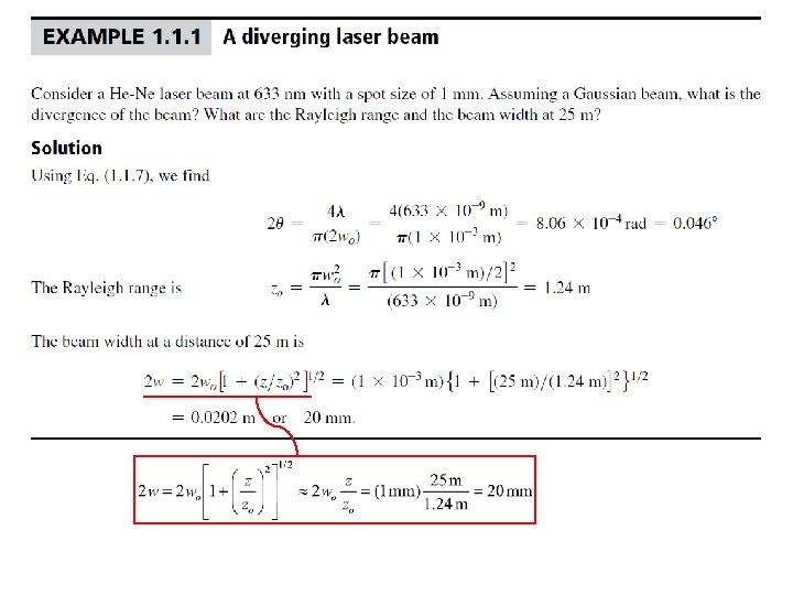
Gaussian Beam The radiation emitted from a laser can be approximated by a Gaussian beam approximations are widely used in photonics. Wavefronts of a Gaussian light beam
Gaussian Beam The intensity across the beam follows a Gaussian distribution Beam axis Intensity = I(r, z) = [2 P/(pw 2)]exp( 2 r 2/w 2) q = w/z = /(pwo) 2 q = Far field divergence
The Gaussian Intensity Distribution is Not Unusual The Gaussian intensity distribution is also used in fiber optics The fundamental mode in single mode fibers can be approximated with a Gaussian intensity distribution across the fiber core I(r) = I(0)exp( 2 r 2/w 2)
Gaussian Beam 2 q = Far field divergence zo = wo /l 2
Gaussian Beam Rayleigh range
Real and Ideal Gaussian Beams Definition of M 2
Real Gaussian Beam Real beam Correction note: Page 10 in textbook, Equation (1. 1), w should be wr as above and wor should be squared in the parantheses.
Gaussian Beam in an Optical Cavity Two spherical mirrors reflect waves to and from each other. The optical cavity contains a Gaussian beam. This particular optical cavity is symmetric and confocal; the two focal points coincide at F.
Refractive Index When an EM wave is traveling in a dielectric medium, the oscillating electric field polarizes the molecules of the medium at the frequency of the wave The stronger is the interaction between the field and the dipoles, the slower is the propagation of the wave
Refractive Index
Maxwell’s Wave Equation in an isotropic medium A plane wave is a solution of Maxwell’s wave equation Ex = Eo cos( t kz + ) The phase velocity of this plane wave in the medium is given by The phase velocity in vacuum is
Phase Velocity and er The relative permittivity r measures the ease with which the medium becomes polarized and hence it indicates the extent of interaction between the field and the induced dipoles. For an EM wave traveling in a nonmagnetic dielectric medium of relative permittivity r, the phase velocity v is given by
Refractive Index n Phase Velocity and er Refractive index n definition
Optical frequencies Typical frequencies that are involved in optoelectronic devices are in the infrared (including far infrared), visible, and UV, and we generically refer to these frequencies as optical frequencies Somewhat arbitrary range: Roughly 1012 Hz to 1016 Hz
Low frequency (LF) relative permittivity er(LF) and refractive index n.
Refractive Index and Propagation Constant ko Free-space propagation constant (wave vector) ko 2π/ o Free-space wavelength k Propagation constant (vave vector) in the medium Wavelength in the medium In noncrystalline materials such as glasses and liquids, the material structure is the same in all directions and n does not depend on the direction. The refractive index is then isotropic
Refractive Index and Wavelength It is customary to drop the subscript o on k and kmedium = nk In free space medium = /n
Refractive Index and Isotropy Crystals, in general, have nonisotropic, or anisotropic, properties Typically noncrystalline solids such as glasses and liquids, and cubic crystals are optically isotropic; they possess only one refractive index for all directions
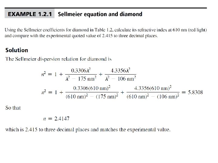
n depends on the wavelength Dispersion relation: n = n( ) The simplest electronic polarization gives Nat =Number of atoms per unit volume Z = Number of electrons in the atom (atomic number) o = A “resonant frequency” Sellmeier Equation
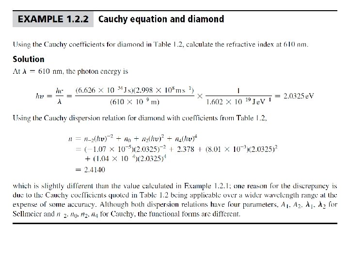
n depends on the wavelength Cauchy dispersion relation n = n(u) n = n-2(hu)-2 + n 0 + n 2(hu)2 + n 4(hu)4
n depends on the wavelength
Group Velocity and Group Index There are no perfect monochromatic waves We have to consider the way in which a group of waves differing slightly in wavelength travel along the z-direction
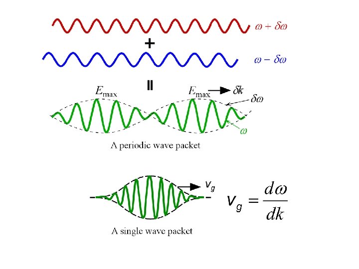
Group Velocity and Group Index When two perfectly harmonic waves of frequencies and + and wavevectors k k and k + k interfere, they generate a wave packet which contains an oscillating field at the mean frequency that is amplitude modulated by a slowly varying field of frequency . The maximum amplitude moves with a wavevector k and thus with a group velocity that is given by
Group Velocity Two slightly different wavelength waves traveling in the same direction result in a wave packet that has an amplitude variation that travels at the group velocity.
Group Velocity Consider two sinusoidal waves that are close in frequency, that is, they have frequencies and + . Their wavevectors will be k k and k + k. The resultant wave is Ex(z, t) = Eocos[( )t (k k)z] + Eocos[( + )t (k + k)z] By using the trigonometric identity cos. A + cos. B = 2 cos[1/2(A B)]cos[1/2(A + B)] we arrive at Ex(z, t) = 2 Eocos[( )t ( k)z][cos( t kz)]