
Optics Metrology at ALBA Josep Nicolas ALBA synchrotron
Optics Metrology at ALBA Josep Nicolas ALBA synchrotron light Facility josep. nicolas@cells. es www. cells. es
Optics Metrology at ALBA Josep Nicolas ALBA synchrotron light Facility Outline 1. The Optics Lab 2. The NOM instrument 3. Some applications josep. nicolas@cells. es www. cells. es
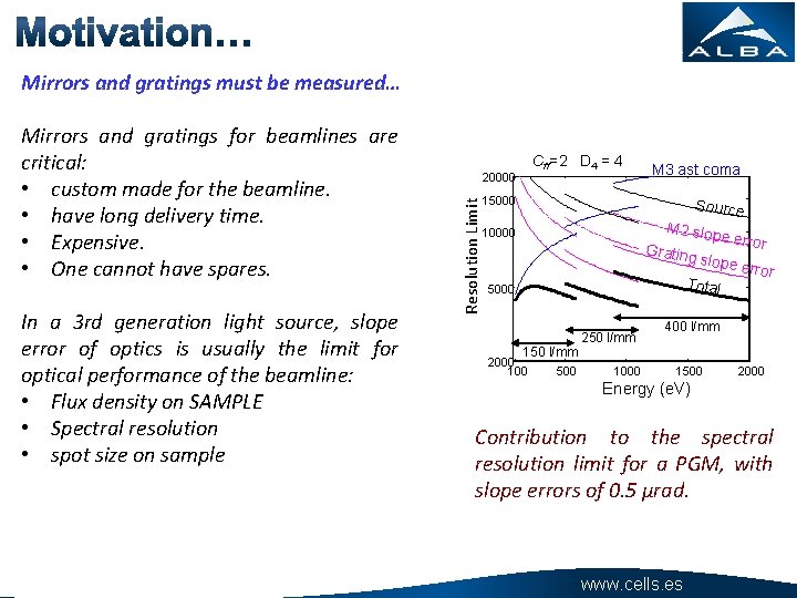
Mirrors and gratings must be measured… In a 3 rd generation light source, slope error of optics is usually the limit for optical performance of the beamline: • Flux density on SAMPLE • Spectral resolution • spot size on sample Cff=2 D 4 = 4 20000 Resolution Limit Mirrors and gratings for beamlines are critical: • custom made for the beamline. • have long delivery time. • Expensive. • One cannot have spares. M 3 ast coma 15000 Source M 2 slo pe 10000 Grating error slope e rror Total 5000 250 l/mm 400 l/mm 150 l/mm 2000 100 500 1000 1500 2000 Energy (e. V) Contribution to the spectral resolution limit for a PGM, with slope errors of 0. 5 μrad. www. cells. es
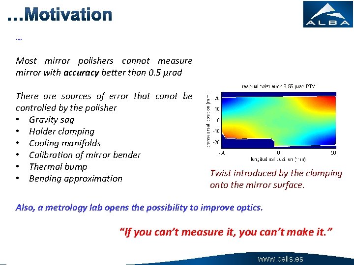
… Most mirror polishers cannot measure mirror with accuracy better than 0. 5 μrad There are sources of error that canot be controlled by the polisher • Gravity sag • Holder clamping • Cooling manifolds • Calibration of mirror bender • Thermal bump • Bending approximation Twist introduced by the clamping onto the mirror surface. Also, a metrology lab opens the possibility to improve optics. “If you can’t measure it, you can’t make it. ” www. cells. es

Mirror 400 mm (toroidal) Mirror 1200 mm (plane elliptic) Diffraction grating (170 mm) 37 mirrors and diffraction gratings 14 bent onto plano elliptic 7 toroidal 7 longer than 600 mm >85% better than 1 μrad >50 % better than 0. 5 μrad Maximum radius specified 22 km Minimum radius (sagittal) 35 mm Best measured error 55 nrad About 30% were initially out of specs www. cells. es
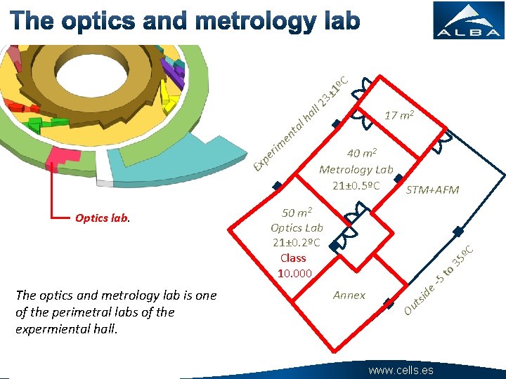
C 1º 3± ha ll 2 The optics and metrology lab is one of the perimetral labs of the expermiental hall. 5 to 3 5 ºC 50 m 2 Optics Lab 21± 0. 2ºC Class 10. 000 STM+AFM Annex e- Optics lab. 40 m 2 Metrology Lab 21± 0. 5ºC Ou ts id Ex pe rim en t al 17 m 2 www. cells. es
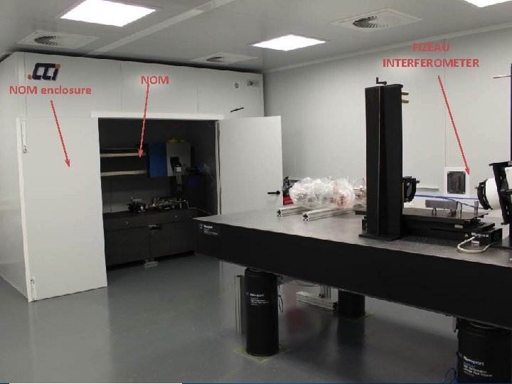
FIZEAU INTERFEROMETER NOM enclosure NOM www. cells. es
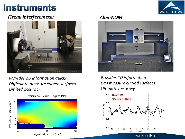
Fizeau interferometer Alba-NOM Provides 2 D information quickly. Difficult to measure curved surfaces. Limited accuracy. Provides 1 D information Can measure curved surfaces Ultimate accuracy R=75 m 36 nrad RMS www. cells. es
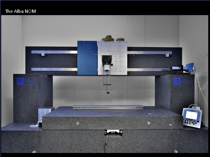
The Alba NOM www. cells. es
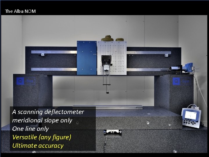
The Alba NOM A scanning deflectometer meridional slope only One line only Versatile (any figure) Ultimate accuracy www. cells. es
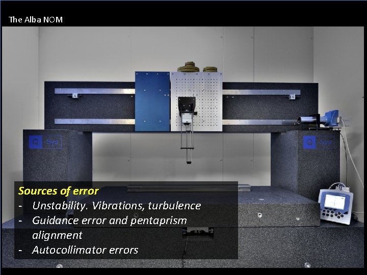
The Alba NOM Sources of error - Unstability. Vibrations, turbulence - Guidance error and pentaprism alignment - Autocollimator errors www. cells. es
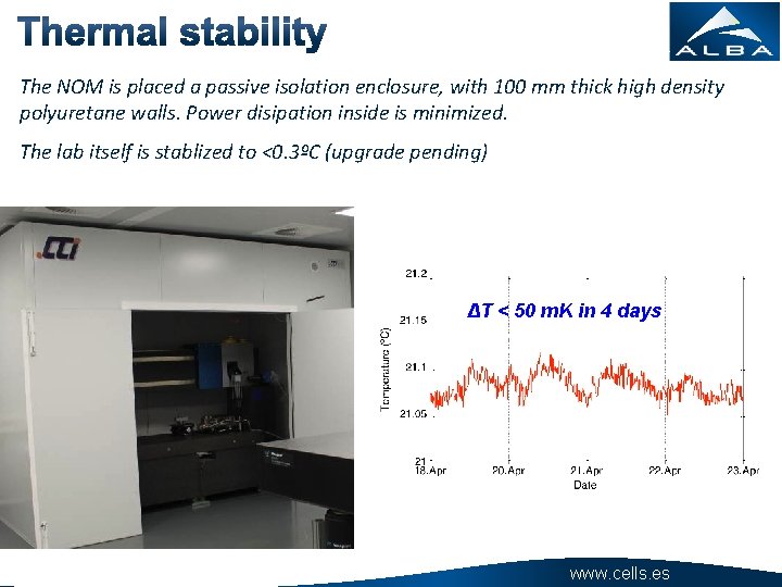
The NOM is placed a passive isolation enclosure, with 100 mm thick high density polyuretane walls. Power disipation inside is minimized. The lab itself is stablized to <0. 3ºC (upgrade pending) ΔT < 50 m. K in 4 days www. cells. es
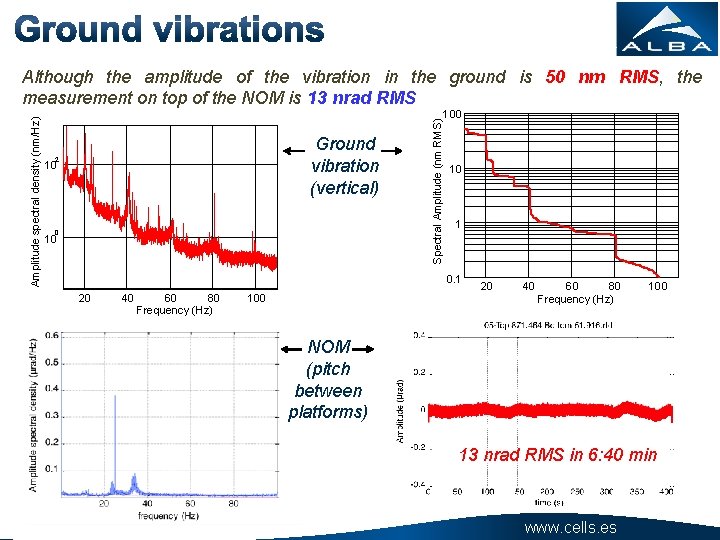
Ground vibration (vertical) 2 10 0 10 Spectral Amplitude (nm RMS) Amplitude spectral density (nm/Hz) Although the amplitude of the vibration in the ground is 50 nm RMS, the measurement on top of the NOM is 13 nrad RMS 100 10 1 0. 1 20 40 60 80 Frequency (Hz) 100 NOM (pitch between platforms) 13 nrad RMS in 6: 40 min www. cells. es
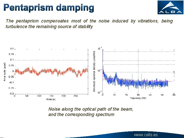
The pentaprism compensates most of the noise induced by vibrations, being turbulence the remaining source of stability Noise along the optical path of the beam, and the corresponding spectrum www. cells. es
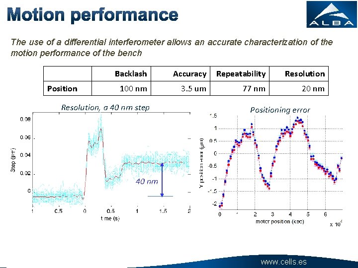
The use of a differential interferometer allows an accurate characterization of the motion performance of the bench Position Backlash Accuracy Repeatability Resolution 100 nm 3. 5 um 77 nm 20 nm Resolution, a 40 nm step Positioning error 40 nm www. cells. es
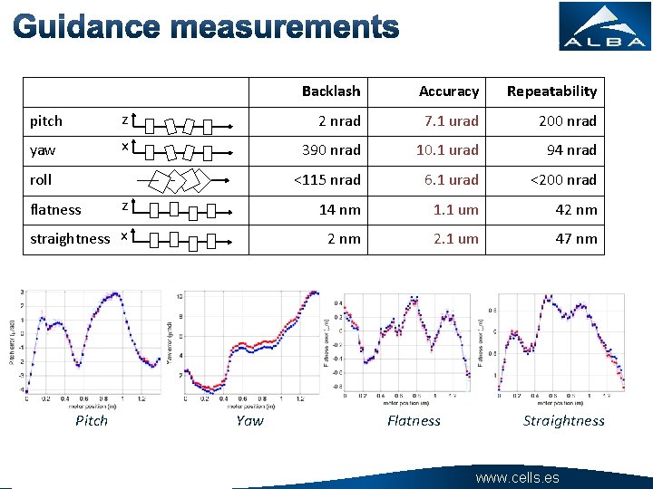
Backlash Accuracy Repeatability pitch z 2 nrad 7. 1 urad 200 nrad yaw x 390 nrad 10. 1 urad 94 nrad <115 nrad 6. 1 urad <200 nrad z 14 nm 1. 1 um 42 nm straightness x 2 nm 2. 1 um 47 nm roll flatness Pitch Yaw Flatness Straightness www. cells. es
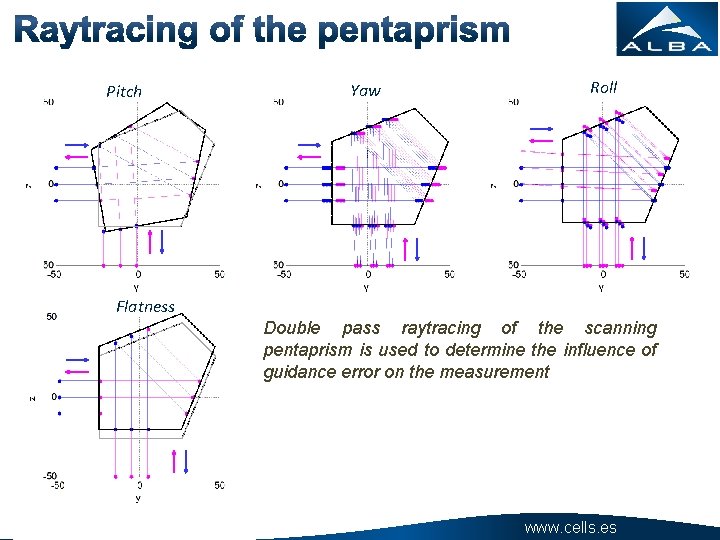
Pitch Yaw Roll Flatness Double pass raytracing of the scanning pentaprism is used to determine the influence of guidance error on the measurement www. cells. es
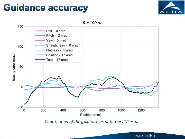
R = 100 m Contribution of the guidance error to the LTP error www. cells. es
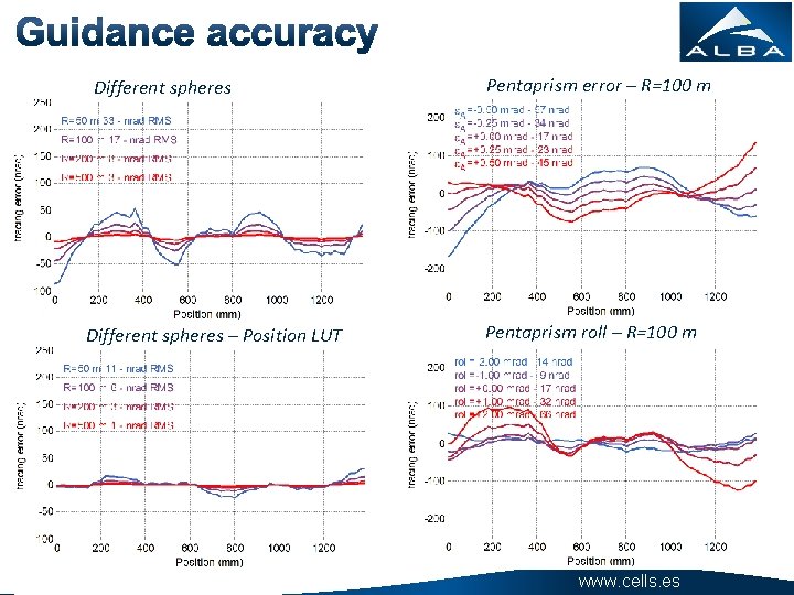
Different spheres – Position LUT Pentaprism error – R=100 m Pentaprism roll – R=100 m www. cells. es
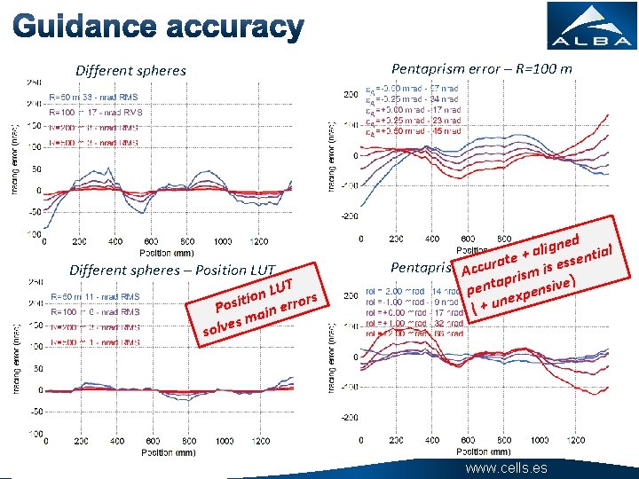
Different spheres – Position LUT UT L n rs tio Posi ain erro es m v l o s Pentaprism error – R=100 m ned al g i l a ti + n e e t s a s r Pentaprism. Aroll isme ccu– R=100 m s i r ) ap pent xpensive e ( + un www. cells. es
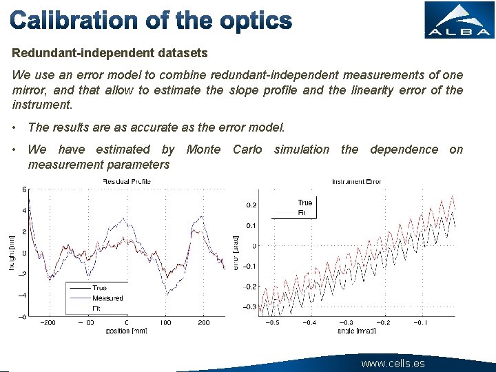
Redundant-independent datasets We use an error model to combine redundant-independent measurements of one mirror, and that allow to estimate the slope profile and the linearity error of the instrument. • The results are as accurate as the error model. • We have estimated by Monte Carlo simulation the dependence on measurement parameters www. cells. es
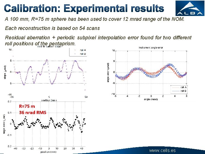
A 100 mm, R=75 m sphere has been used to cover 12 mrad range of the NOM. Each reconstruction is based on 54 scans Residual aberration + periodic subpixel interpolation error found for two different roll positions of the pentaprism. R=75 m 36 nrad RMS www. cells. es
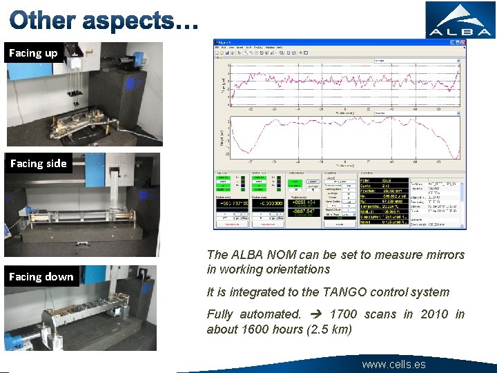
Facing up Facing side Facing down The ALBA NOM can be set to measure mirrors in working orientations It is integrated to the TANGO control system Fully automated. 1700 scans in 2010 in about 1600 hours (2. 5 km) www. cells. es
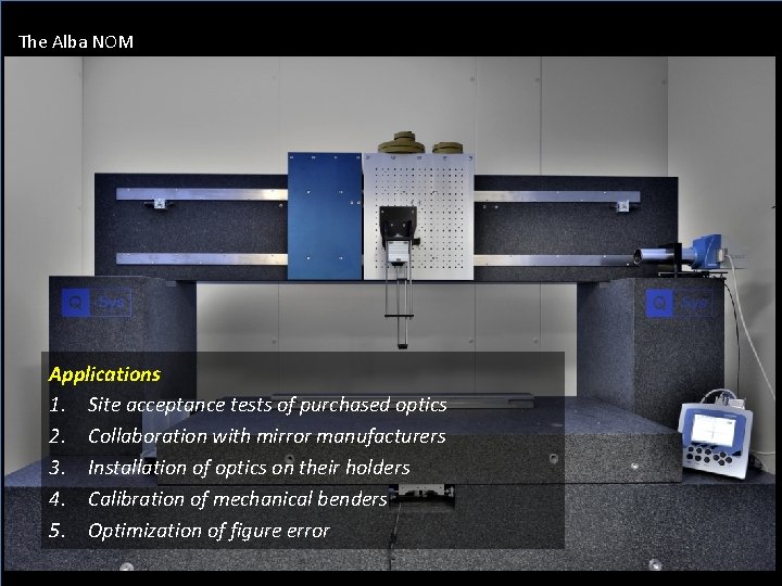
The Alba NOM Applications 1. Site acceptance tests of purchased optics 2. Collaboration with mirror manufacturers 3. Installation of optics on their holders 4. Calibration of mechanical benders 5. Optimization of figure error www. cells. es
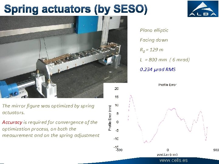
Plano elliptic Facing down R 0 = 129 m L = 800 mm ( 6 mrad) 0. 234 μrad RMS The mirror figure was optimized by spring actuators. Accuracy is required for convergence of the optimization process, on both the measurement and on the spring adjustment www. cells. es
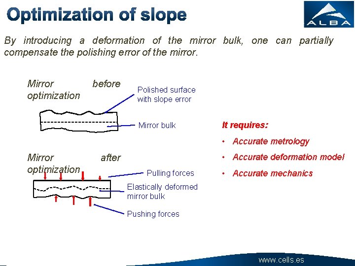
By introducing a deformation of the mirror bulk, one can partially compensate the polishing error of the mirror. Mirror optimization before Polished surface with slope error Mirror bulk It requires: • Accurate metrology Mirror optimization • Accurate deformation model after Pulling forces • Accurate mechanics Elastically deformed mirror bulk Pushing forces www. cells. es
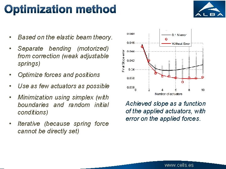
• Based on the elastic beam theory. • Separate bending (motorized) from correction (weak adjustable springs) • Optimize forces and positions • Use as few actuators as possible • Minimization using simplex (with boundaries and random initial conditions) • Iterative (because spring force cannot be directly set) Achieved slope as a function of the applied actuators, with error on the applied forces. www. cells. es
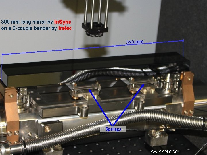
300 mm long mirror by In. Sync on a 2 -couple bender by Irelec. 390 mm Springs www. cells. es
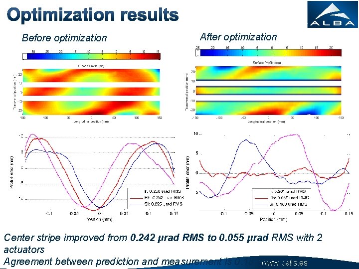
Before optimization After optimization Center stripe improved from 0. 242 μrad RMS to 0. 055 μrad RMS with 2 actuators Agreement between prediction and measurement is 0. 18 nm RMS www. cells. es
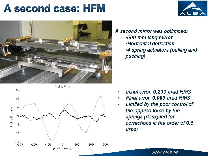
A second mirror was optimized: • 600 mm long mirror • Horizontal deflection • 4 spring actuators (pulling and pushing) • • • Initial error: 0. 211 μrad RMS Final error: 0. 083 μrad RMS Limited by the poor control of the applied force by the springs (designed for corrections in the order of 0. 5 μrad) www. cells. es
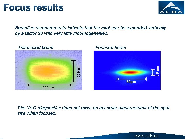
Beamline measurements indicate that the spot can be expanded vertically by a factor 20 with very little inhomogeneities. Defocused beam 10 μm 110 μm Focused beam 50μm 220 μm The YAG diagnostics does not allow an accurate measurement of the spot size when focused. www. cells. es
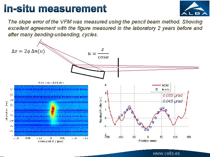
The slope error of the VFM was measured using the pencil beam method. Showing excellent agreement with the figure measured in the laboratory 2 years before and after many bending-unbending, cycles. 0. 055 μrad 0. 045 μrad www. cells. es
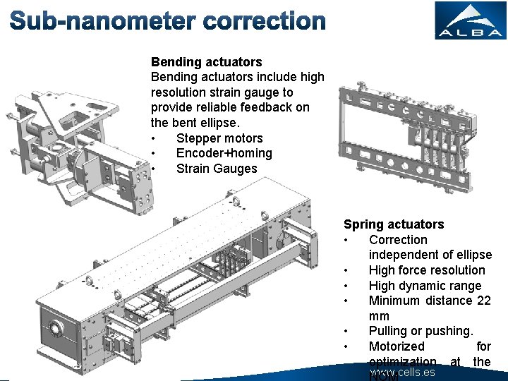
Bending actuators include high resolution strain gauge to provide reliable feedback on the bent ellipse. • Stepper motors • Encoder+homing • Strain Gauges Spring actuators • Correction independent of ellipse • High force resolution • High dynamic range • Minimum distance 22 mm • Pulling or pushing. • Motorized for optimization at the www. cells. es
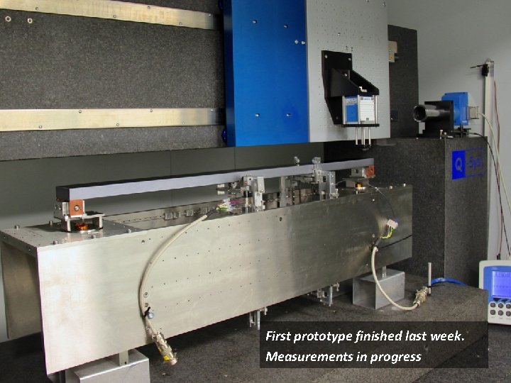
First prototype finished last week. Measurements in progress www. cells. es
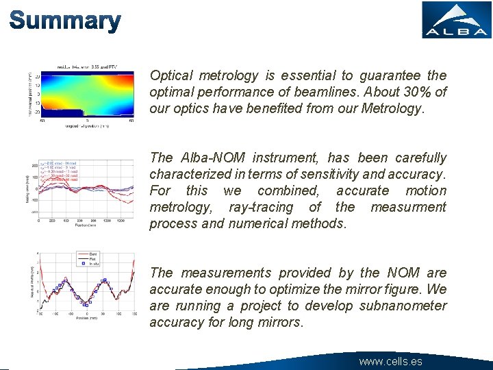
Optical metrology is essential to guarantee the optimal performance of beamlines. About 30% of our optics have benefited from our Metrology. The Alba-NOM instrument, has been carefully characterized in terms of sensitivity and accuracy. For this we combined, accurate motion metrology, ray-tracing of the measurment process and numerical methods. The measurements provided by the NOM are accurate enough to optimize the mirror figure. We are running a project to develop subnanometer accuracy for long mirrors. www. cells. es
Optics Group Juan Carlos Martínez Team Josep Vidal Igors Sics Iulian Preda Juan Campos (UAB) We are a small group but we have strong support from many…. Other facilities… Frank Siewert (HZB) Daniele Cocco (LCLS) Mourad Idir (NSLS II) Muriel Thomasset (Soleil) Amparo Vivo (ESRF) Valeriy Yashchuck (ALS) Ray Barrett (ESRF) … Administration Laura Campos … Computing Zbigniew Reszela and Controls Sergi Blanch Guifré Cuní Sergi Pusó Ramon Escribà … Engineering Carles Colldelram Edmundo Fraga José Ferrer Ricardo Valcárcel … Claude Ruget IRPI (France) Alba All beamline scientists beamlines … www. cells. es
- Slides: 36