IR Mechanics Service Space S Tanaka KEK 12
 12 th B 2 GM")

 12 th B 2 GM")

 design DOCK possibility to add tungsten The latest design file is:")


: width=203 mm,")


. 11 th. B 2 GM PXD requirement")


")
 Mechanics design is")
 • • The first priority of SVD designer is")
 2012 (preparation for VXD mock-up) 13 th B 2 GM(2012 Nov)")


- Slides: 36
IR Mechanics, Service Space S. Tanaka (KEK) 12 th B 2 GM
24 th
Beam Pipe and IR Mechanics Status S. Tanaka (KEK) 12 th B 2 GM
Beam pipe production Ti part has produced last month Production design by Kinzoku giken Cutting test of crotch part • IP chamber outer pipe has ordered, will deliver in Aug. • Inner pipe and crotch part production will be start, when optimization of BG simulation is finished.
QCS R-side (forward) design DOCK possibility to add tungsten The latest design file is: http: //kds. kek. jp/conference. Display. py? conf. Id=10423 Additional iron
PXD/SVD dock design
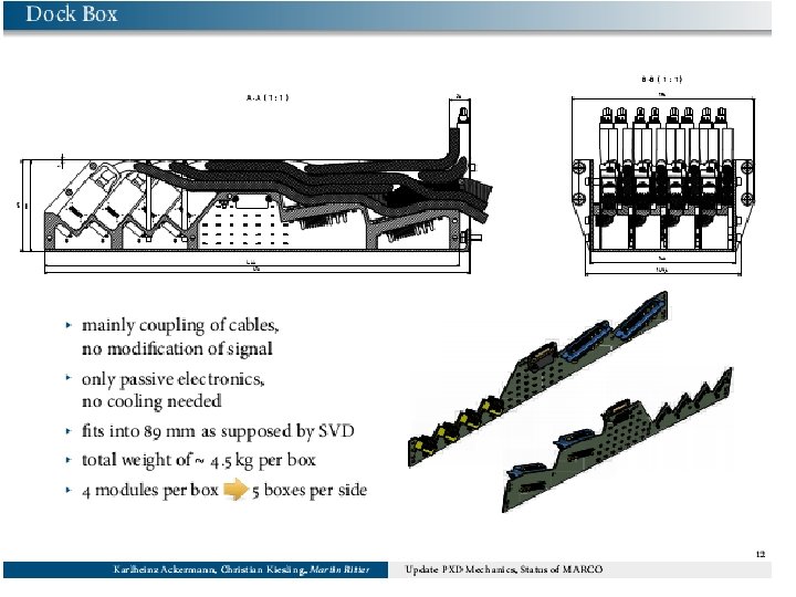
SVD 2 DOCKs Installed DOCK boxes mounted on CDC end wall Contained SVD 2 repeaters Made of copper (heavy) with water cooling on 3 sides A bit tricky to close Belle due to gravitational sag into QCS Future boxes should be lighter and/or a bit smaller (especially height) 3/8/2021 7
DOCK Space for SVD and PXD Box outer dimensions (without lid flanges): width=203 mm, height=89 mm, depth=409 mm Total weight: 3. 9 kg Using this design, we need BW side: 5 boxes (=SVD 2) FW side: 3 boxes (less than SVD 2) All boxes are fully used (6 x 8 = 48 FADCs) Still enough room for PXD boxes… 3/8/2021 9
Overall DOCK Arrangement Cooling pipe connection box should be also placed on there D SVD PX Backward Space for shielding Forward (PXD box is only a placeholder) 3/8/2021 10
Remaining issue is cooling
Inner Service Space related to Shielding Modified by PXD Power cable requirement after IDM (Apr. )
Errata: IR service estimation report on IDM(April). 11 th. B 2 GM PXD requirement 12 th. B 2 GM • I had misunderstood two 8. 6 mmf cables as 2*8. 6 mm 2 cable, • Updated size is 9. 4 mmf
The narrowest region between QCS and CDC On belle case, 9 mm of clearance (open space) has assigned between CDC and QCS To be proved The design of this space is not changed, but support bar position has moved Circumference : 1287 mm Block size: ~100 mm ->~880 mm available for services To be proved Belle and machine group agree to take similar clearance between detector and machine structure (9 mm)
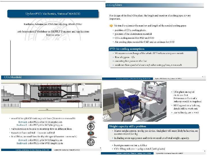
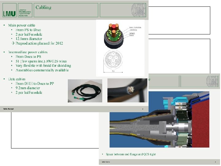
Space requirement between QCS and CDC Cooling pipes: Forward Name Diameter # of pieces Cooling pipe(water) 6 mm 8 Cooling pipes(PF) 6 mm 1 CO 2 cooling 12 mm 4 PXD+SVD N cooling 12 mm 6 PXD+SVD Service estimation by each sub-detector on last B 2 GM Inlet and outlet CO 2 tubes are thermally insulated by cupper tube Beam pipe
Space requirement between QCS and CDC Cables: Forward Name Diameter # of pieces Data cables 9. 4 mmf(AWG 26) 40 Power cables 9. 6 mmf (changed from 1× 7 mm) 20 Fiber sensors 6× 3 mm 1 Cables 1× 32 mm (AWG 30) (1. 5 mmt for twist pair) 122 Fibers 1 mmf (a few) PXD SVD Monitor 1 mmf (a few) In addition, 8 BPM cables (3 mmf) and some monitor cables In order to take the space allocation easier, I defined cable set: as an example: 20 Cable set consists: 2 PXD data cable +1 PXD power cable + 6 SVD cables
The cable space at the head of QCS • 769. 3 mm: the minimum circumference on QCS cabling 24 5 m m at ad he of S QC • Support bracket is not included
Service space dependence on # of stacking SVD cables revised version with two layers(Forward) Cable set width # of SVD cables stacked PXD cables 6 7 32 mm 8 9 9. 4 mm*2 (data) +9. 6 mm (power) 10 Break 9 mm law 15 Thickness of # of cable Service area cable sets (circumference: 769 mm) 11 mm 20 984 mm 12. 5 mm 18 920 mm 14 mm 16 856 mm 15. 5 mm 14 792 mm 17 mm 13 760 mm 22. 5 mm 9 Larger than space 630 mm Ex: 32 mm*16(sets) +(9. 4 mm*2+9. 6 mm)*10+ 12 mm*5(pipes)=356+mm SVD cables (stacking 6 -15) PXD power PXD data cable PXD power cables should reduce the size! more than 20% space margin is required for smooth installation
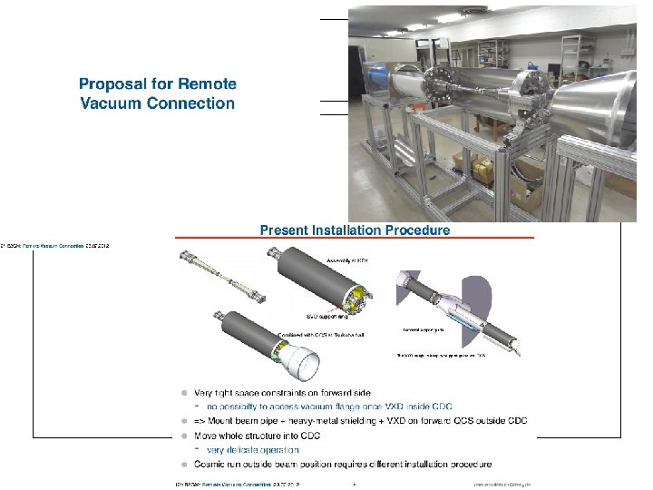
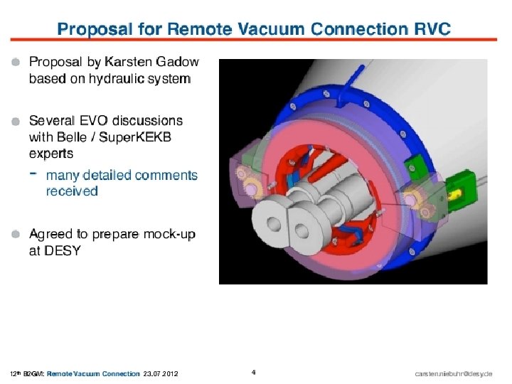
Service space for new concept of vacuum connection (by DESY group) Mechanics design is not optimized, however space for cooling pipes and SVD cables should be take into account on final design
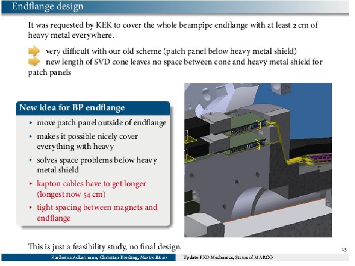
Discussion summary (VXD designers meeting) • • The first priority of SVD designer is to solve 3 rd layer's Hybrid cooling issue VXD mechanical mockup (check for service space or assembly procedure) – The design should be finalize at 13 th. B 2 GM(2012 Nov. ) – The mock-up should be shown at 14 th. B 2 GM(2013 Mar. ) – The design requirement (i. e. connection with endflange)should be summarized at next SVD/PXD meeting in Sep. – KEK mockup design and production should wait until decision • • • The idea of ladder mount procedure is highly welcome Tanaka have to send Step file of heavy metal to VXD designers PXD ladder assembly will be done at MPI – Simple mount procedure on beam pipe =>good new for KEK group • The place of PXD PP at between SVD support cone and heavy metal – discussed on SVD/PXD meeting in Sep. – which is important for new installation procedure • The material selection and production procedure of SVD support structure – should decide at 14 th B 2 GM (2013 Mar. ) – Titanium option should be take care in parallel with base idea – Vienna, MPI and KEK group will start test production of CFRP cone and gluing test. (Vienna group will also study thermal stress effect) • Please keep watch the status of beam pipe production. The precision of this may cause serious situation in particular for PXD mount.
Schedule (IR mechanics) 2012 (preparation for VXD mock-up) 13 th B 2 GM(2012 Nov) the mechanical mock up design (final) Beam pipe production(for BEASTII) 2013 VXD mechanical mockup will be ready (2013 Mar B 2 GM) Mechanics check -> installation test, service work test Beam pipe production 2014 SVD Ladder mount start (SVD) (2014 Sep. ) End of 2014 -> BEASTII Beam pipe production 2015 Starting VXD assembly(Aug-Sep) (CR test ) and installation 31
• We still have many kind of remaining issues. • Now we have good collaboration by MPI, Vienna, DESY and KEK for fighting to solve mechanics issues • We will keep to have frequent discussion to solve them.
backup
Activity at Tsukuba hall
VXD mock-up @ Tsukuba Mock-up for VXD installation study CDC inner cylinder Shields Vertex Detector QCS forward The mockup for installation test This mock-up may be used for BEAST II
Assembly SVD table design Gluing support jigs with good position precision SVD 2 case SVD ladder mount table will also used for end-ring gluing procedure