Introducing the Specifications of the MEF 23 1



- Slides: 41
Introducing the Specifications of the MEF 23. 1: Class of Service Phase 2 Implementation Agreement 1
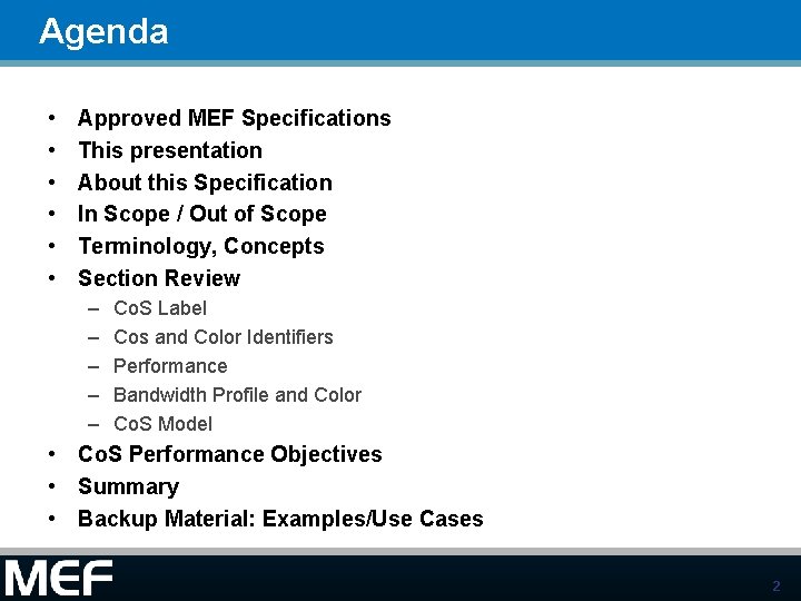
Agenda • • • Approved MEF Specifications This presentation About this Specification In Scope / Out of Scope Terminology, Concepts Section Review – – – Co. S Label Cos and Color Identifiers Performance Bandwidth Profile and Color Co. S Model • Co. S Performance Objectives • Summary • Backup Material: Examples/Use Cases 2
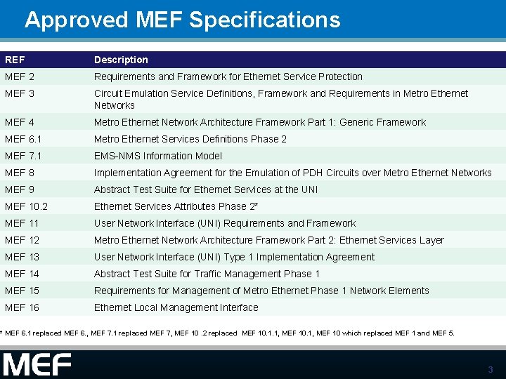
Approved MEF Specifications REF Description MEF 2 Requirements and Framework for Ethernet Service Protection MEF 3 Circuit Emulation Service Definitions, Framework and Requirements in Metro Ethernet Networks MEF 4 Metro Ethernet Network Architecture Framework Part 1: Generic Framework MEF 6. 1 Metro Ethernet Services Definitions Phase 2 MEF 7. 1 EMS-NMS Information Model MEF 8 Implementation Agreement for the Emulation of PDH Circuits over Metro Ethernet Networks MEF 9 Abstract Test Suite for Ethernet Services at the UNI MEF 10. 2 Ethernet Services Attributes Phase 2* MEF 11 User Network Interface (UNI) Requirements and Framework MEF 12 Metro Ethernet Network Architecture Framework Part 2: Ethernet Services Layer MEF 13 User Network Interface (UNI) Type 1 Implementation Agreement MEF 14 Abstract Test Suite for Traffic Management Phase 1 MEF 15 Requirements for Management of Metro Ethernet Phase 1 Network Elements MEF 16 Ethernet Local Management Interface * MEF 6. 1 replaced MEF 6. , MEF 7. 1 replaced MEF 7, MEF 10. 2 replaced MEF 10. 1. 1, MEF 10 which replaced MEF 1 and MEF 5. 3
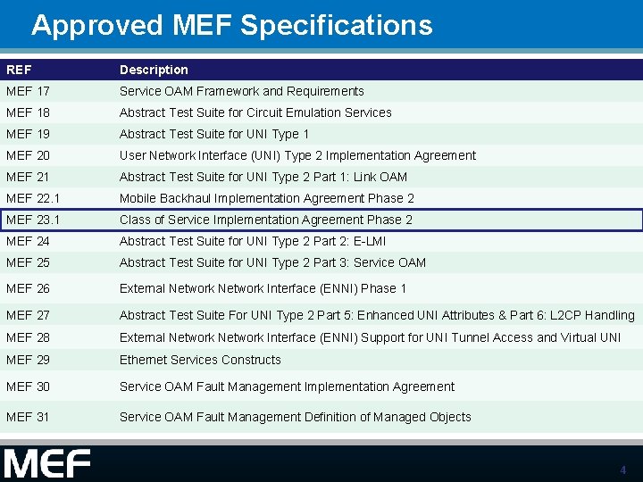
Approved MEF Specifications REF Description MEF 17 Service OAM Framework and Requirements MEF 18 Abstract Test Suite for Circuit Emulation Services MEF 19 Abstract Test Suite for UNI Type 1 MEF 20 User Network Interface (UNI) Type 2 Implementation Agreement MEF 21 Abstract Test Suite for UNI Type 2 Part 1: Link OAM MEF 22. 1 Mobile Backhaul Implementation Agreement Phase 2 MEF 23. 1 Class of Service Implementation Agreement Phase 2 MEF 24 Abstract Test Suite for UNI Type 2 Part 2: E-LMI MEF 25 Abstract Test Suite for UNI Type 2 Part 3: Service OAM MEF 26 External Network Interface (ENNI) Phase 1 MEF 27 Abstract Test Suite For UNI Type 2 Part 5: Enhanced UNI Attributes & Part 6: L 2 CP Handling MEF 28 External Network Interface (ENNI) Support for UNI Tunnel Access and Virtual UNI MEF 29 Ethernet Services Constructs MEF 30 Service OAM Fault Management Implementation Agreement MEF 31 Service OAM Fault Management Definition of Managed Objects 4
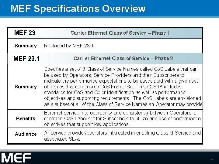
MEF Specifications Overview MEF 23 Summary Carrier Ethernet Class of Service – Phase I Replaced by MEF 23. 1 Carrier Ethernet Class of Service – Phase 2 Summary Specifies a set of 3 Class of Service Names called Co. S Labels that can be used by Operators, Service Providers and their Subscribers to indicate the performance expectations to be associated with a given set of frames that comprise a Co. S Frame Set. This Co. S IA includes Standardized standards for Co. S and Color identification as well as performance Services objectives and supporting requirements. The Co. S Labels are envisioned as a subset of all of the Class of Service Names an Operator may provide. Benefits Ethernet service interoperability and consistency between Operators, a common Co. S Label set for Subscribers to utilize and use of performance objectives that support key applications. Audience All service provider/operators interested in enabling Class of Service and associated SLAs. 5
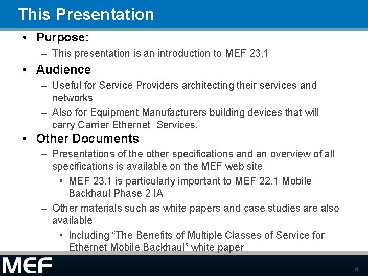
This Presentation • Purpose: – This presentation is an introduction to MEF 23. 1 • Audience – Useful for Service Providers architecting their services and networks – Also for Equipment Manufacturers building devices that will carry Carrier Ethernet Services. • Other Documents – Presentations of the other specifications and an overview of all specifications is available on the MEF web site • MEF 23. 1 is particularly important to MEF 22. 1 Mobile Backhaul Phase 2 IA – Other materials such as white papers and case studies are also available • Including “The Benefits of Multiple Classes of Service for Ethernet Mobile Backhaul” white paper 6
About the Specification This Implementation Agreement is motivated by the need to introduce and define specific “classes” or Co. S Names called Co. S Labels that will deliver a commitment for a particular level of performance for a set of Service or ENNI Frames (e. g. , those belonging to a particular Co. S Frame Set) from the Service Provider or Operator. This is to further develop Carrier Ethernet services that are interoperable and predictably support Subscriber applications. For example, Operators and Service Providers that connect MENs will be able to do so with a set of commonly understood Co. S Labels, Co. S IDs and CPOs in addition to any bilateral Co. S Names they want to support. This Co. S IA normative language is primarily applicable to Subscribers, Service Providers and Operators who desire Co. S Name interoperability across EIs. The requirements are developed based on the needs of Subscribers and their applications. Compliance with the Co. S Labels in this IA does not limit an Operator from providing additional Co. S Names using Co. S Identifier values (e. g. , PCP) that are left unused in this IA. Examples of additional Co. S Names could include Operator defined Co. S Names in addition to the specific MEF Co. S Labels defined in this IA. Note that the Co. S Performance Objective (CPO) and Parameter values are specified in this IA as maximums or minimums and thus do not limit Operators from providing conformant values that are less than the maximums or greater than the minimums. These other values could be described as more stringent, i. e. , having more rigor or severity with respect to the standard or requirement value. 7
Overview of MEF 23. 1 8
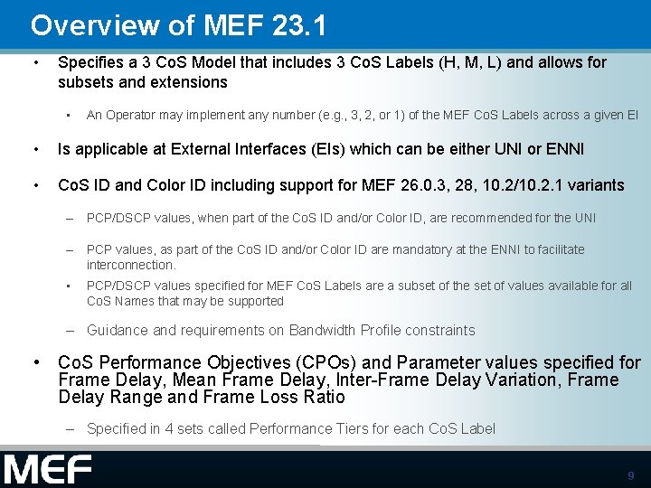
Overview of MEF 23. 1 • Specifies a 3 Co. S Model that includes 3 Co. S Labels (H, M, L) and allows for subsets and extensions • An Operator may implement any number (e. g. , 3, 2, or 1) of the MEF Co. S Labels across a given EI • Is applicable at External Interfaces (EIs) which can be either UNI or ENNI • Co. S ID and Color ID including support for MEF 26. 0. 3, 28, 10. 2/10. 2. 1 variants – PCP/DSCP values, when part of the Co. S ID and/or Color ID, are recommended for the UNI – PCP values, as part of the Co. S ID and/or Color ID are mandatory at the ENNI to facilitate interconnection. • PCP/DSCP values specified for MEF Co. S Labels are a subset of the set of values available for all Co. S Names that may be supported – Guidance and requirements on Bandwidth Profile constraints • Co. S Performance Objectives (CPOs) and Parameter values specified for Frame Delay, Mean Frame Delay, Inter-Frame Delay Variation, Frame Delay Range and Frame Loss Ratio – Specified in 4 sets called Performance Tiers for each Co. S Label 9
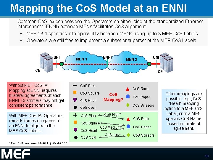
Mapping the Co. S Model at an ENNI Common Co. S lexicon between the Operators on either side of the standardized Ethernet interconnect (ENNI) between MENs facilitates Co. S alignment: • • MEF 23. 1 specifies interoperability between MENs using up to 3 MEF Co. S Labels Operators are still free to implement a subset or superset of the MEF Co. S Labels UNI MEN 1 ENNI MEN 2 UNI CE Without MEF Co. S IA: Mapping at ENNI requires bilateral agreements at each ENNI. Customers may not get consistent performance With MEF Co. S IA: Operators remark frames on egress of an ENNI to align with the MEF Co. S Labels. CE Co. S Plus Co. S Square Co. S Heart Co. S Rock Co. S Mapping? Co. S Scissors Co. S Coal Co. S Plus Co. S Paper Co. S High* Co. S Square Co. S Medium* Co. S Heart Co. S Low* Co. S Coal Co. S Rock Co. S Paper Other mappings are possible; e. g. , Co. S “Heart” mapping option to a MEF Co. S Label, or to a MEN specific Co. S Name based on bilateral agreement. Co. S Scissors * Each Co. S Label associated with particular CPO 10
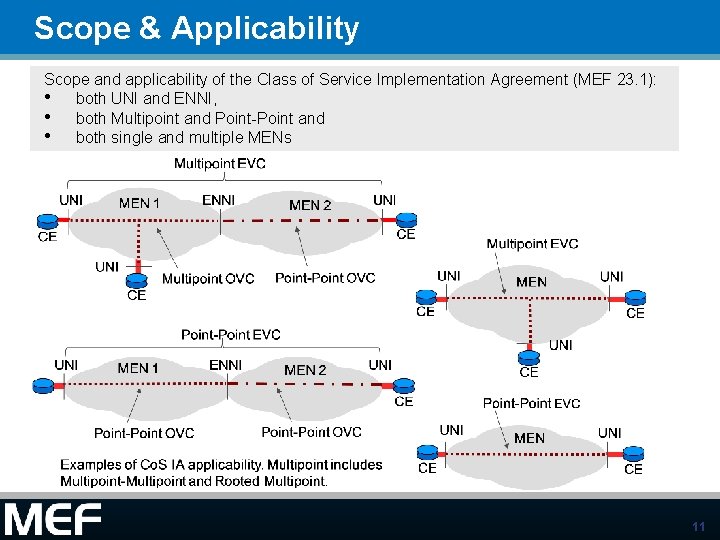
Scope & Applicability Scope and applicability of the Class of Service Implementation Agreement (MEF 23. 1): • both UNI and ENNI, • both Multipoint and Point-Point and • both single and multiple MENs 11
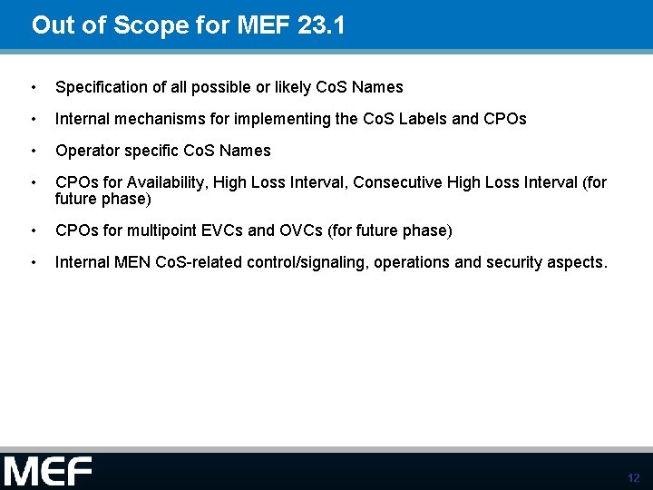
Out of Scope for MEF 23. 1 • Specification of all possible or likely Co. S Names • Internal mechanisms for implementing the Co. S Labels and CPOs • Operator specific Co. S Names • CPOs for Availability, High Loss Interval, Consecutive High Loss Interval (for future phase) • CPOs for multipoint EVCs and OVCs (for future phase) • Internal MEN Co. S-related control/signaling, operations and security aspects. 12
What’s New in Class of Service Phase 2 • • Add new performance metrics for Mean Delay and Delay Range introduced in MEF 10. 2 Introduce four Performance Tiers (PTs) – • Specify Co. S Performance Objectives and associated parameters for pointto-point EVCs and OVCs in each PT – • • PT 1 (Metro), PT 2 (Regional), PT 3 (Continental), PT 4 (Global) Positions for future ATS and/or certification, e. g. , Access Services ATS L 2 CP default Co. S Label Clarification and restructure of “ 3 Co. S Model Tables” Quantitative Delay, Delay Variation/Delay Range, Loss objectives for Single MEN Quantitative Delay, Delay Variation/Delay Range, Loss objectives for Multiple MENs 13
MEF Specification Section Review 14
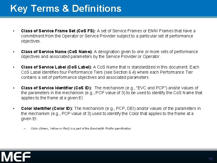
Key Terms & Definitions • Class of Service Frame Set (Co. S FS): A set of Service Frames or ENNI Frames that have a commitment from the Operator or Service Provider subject to a particular set of performance objectives. • Class of Service Name (Co. S Name): A designation given to one or more sets of performance objectives and associated parameters by the Service Provider or Operator. • Class of Service Label (Co. S Label): A Co. S Name that is standardized in this document. Each Co. S Label identifies four Performance Tiers (see Section 6. 4) where each Performance Tier contains a set of performance objectives and associated parameters. • Class of Service Identifier (Co. S ID): The mechanism (e. g. , “EVC and PCP”) and/or values of the parameters in the mechanism (e. g. , PCP value of 3) to be used to identify the Co. S Name that applies to the frame at a given EI. • Color Identifier (Color ID): The mechanism (e. g. , PCP, DEI) and/or values of the parameters in the mechanism (e. g. , PCP value of 3) used to identify the Color that applies to the frame at a given EI. – Color (Green, Yellow or Red) is a part of the Bandwidth Profile specification 15
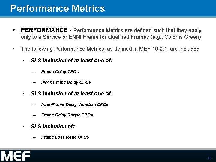
Performance Metrics • PERFORMANCE - Performance Metrics are defined such that they apply only to a Service or ENNI Frame for Qualified Frames (e. g. , Color is Green) • The following Performance Metrics, as defined in MEF 10. 2. 1, are included • • • SLS inclusion of at least one of: – Frame Delay CPOs – Mean Frame Delay CPOs SLS inclusion of at least one of: – Inter-Frame Delay Variation CPOs – Frame Delay Range CPOs SLS inclusion of: – Frame Loss Ratio CPOs 16
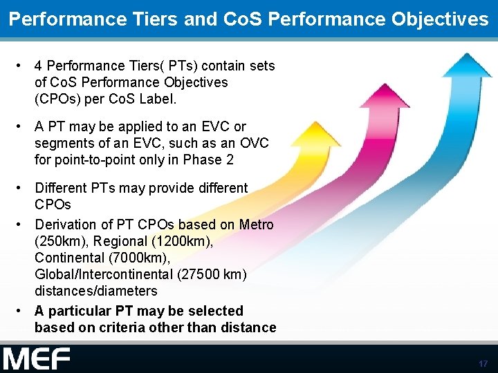
Performance Tiers and Co. S Performance Objectives • 4 Performance Tiers( PTs) contain sets of Co. S Performance Objectives (CPOs) per Co. S Label. • A PT may be applied to an EVC or segments of an EVC, such as an OVC for point-to-point only in Phase 2 • Different PTs may provide different CPOs • Derivation of PT CPOs based on Metro (250 km), Regional (1200 km), Continental (7000 km), Global/Intercontinental (27500 km) distances/diameters • A particular PT may be selected based on criteria other than distance 17
Qualified Frames • Defined in 10. 2 and 26. 1 • Qualified Frames are Service or ENNI Frames that are subject to SLS (including 23. 1 Co. S Performance Objectives) • Exception is Availability metric • Qualified Frames are characterized at a high level as follows: – Frames that ingress at EI (UNI or ENNI) and map to the given EVC or OVC End Point for a given Class of Service Identifier. – Each frame that is subject to an Ingress Bandwidth Profile must have an Ingress Bandwidth Profile compliance of Green, and – Each frame that is not subject to an ingress Bandwidth Profile must have either no Color Indicator or have a Color Indicator that indicates Green 18
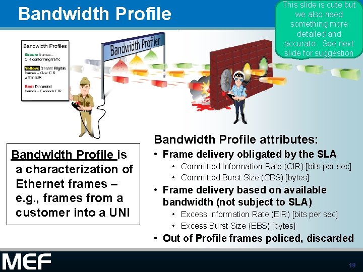
Bandwidth Profile This slide is cute but we also need something more detailed and accurate. See next slide for suggestion Bandwidth Profile attributes: Bandwidth Profile is a characterization of Ethernet frames – e. g. , frames from a customer into a UNI • Frame delivery obligated by the SLA • Committed Information Rate (CIR) [bits per sec] • Committed Burst Size (CBS) [bytes] • Frame delivery based on available bandwidth (not subject to SLA) • Excess Information Rate (EIR) [bits per sec] • Excess Burst Size (EBS) [bytes] • Out of Profile frames policed, discarded 19
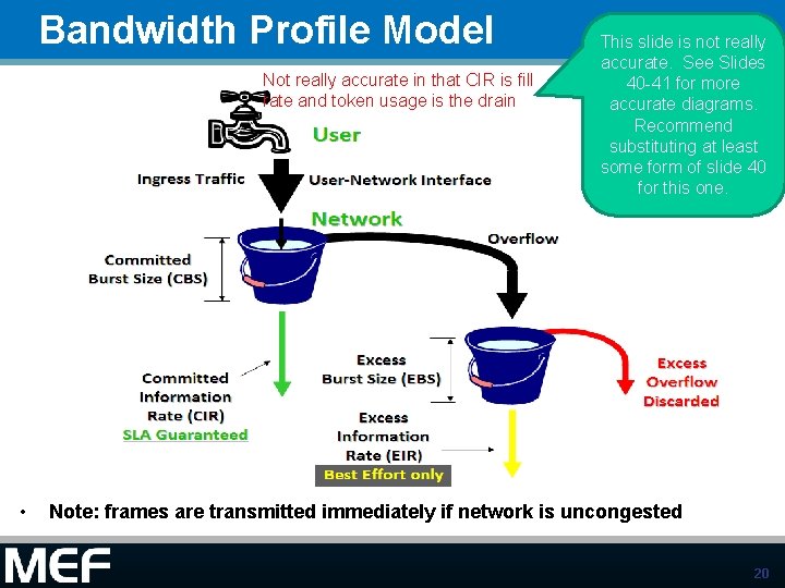
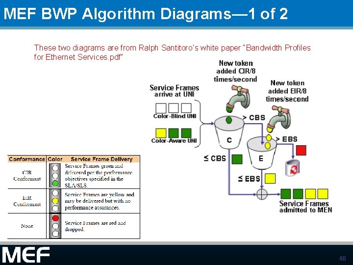
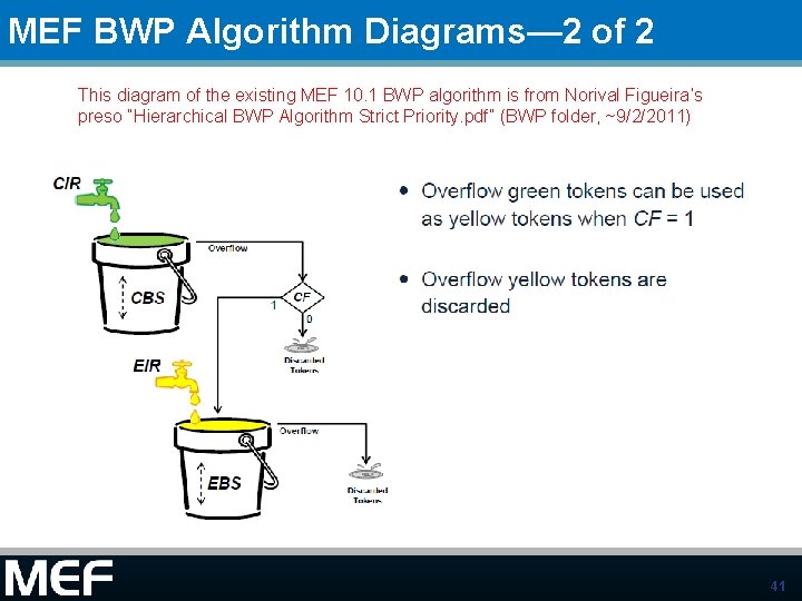
Bandwidth Profile Model Not really accurate in that CIR is fill rate and token usage is the drain • This slide is not really accurate. See Slides 40 -41 for more accurate diagrams. Recommend substituting at least some form of slide 40 for this one. Note: frames are transmitted immediately if network is uncongested 20
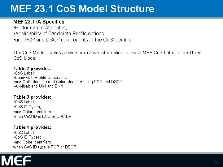
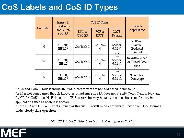
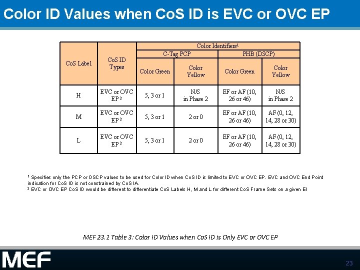
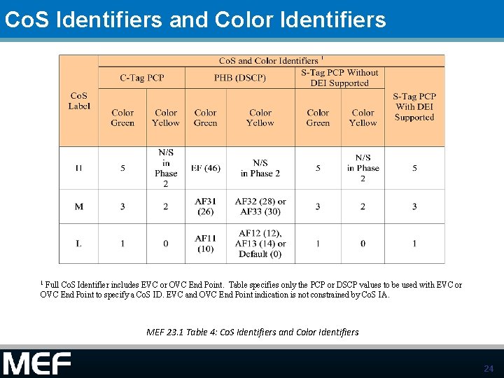
MEF 23. 1 Co. S Model Structure MEF 23. 1 IA Specifies: • Performance Attributes, • Applicability of Bandwidth Profile options, • and PCP and DSCP components of the Co. S Identifier The Co. S Model Tables provide normative information for each MEF Co. S Label in the Three Co. S Model. Table 2 provides: • Co. S Label; • Bandwidth Profile constraints; • and Co. S Identifier and Color Identifier using PCP and DSCP. • Applicable to UNI and ENNI Table 3 provides: • Co. S Label; • Co. S ID Types; • and Color Identifiers when Co. S ID is EVC or OVC EP. Table 4 provides: • Co. S Label; • Co. S ID Types; • and Color Identifiers when Co. S ID type is PCP or DSCP. 21
Co. S Labels and Co. S ID Types Co. S Label Ingress EI Bandwidth Profile Constraints 1 Co. S ID Types EVC or OVC EP PCP or DSCP See Table 3 See Table 4 H CIR>0; EIR 0 2 M CIR>0; EIR 0 See Table 3 See Table 4 L CIR 0; EIR 0 3 See Table 4 L 2 CP Related See Section 6. 5. 1 & [17] Example Applications Vo. IP and Mobile Backhaul Control Near-Real-Time or Critical Data Apps Non-critical Data Apps 1 EBS and Color Mode Bandwidth Profile parameters are not addressed in this table. is not constrained though EIR=0 assumed since this IA does not specify Color Yellow PCP and DSCP for Co. S Label H. Relaxation of EIR constraint may be used in some situations for certain applications such as Mobile Backhaul. 3 Both CIR and EIR = 0 is not allowed as this would result in no conformant Service or ENNI Frames under steady state operation. 2 EIR MEF 23. 1 Table 2: Color Labels and Co. S ID Types in Co. S IA 22
Color ID Values when Co. S ID is EVC or OVC EP Color Identifiers 1 Co. S Label Co. S ID Types C-Tag PCP PHB (DSCP) Color Green Color Yellow H EVC or OVC EP 2 5, 3 or 1 N/S in Phase 2 EF or AF (10, 26 or 46) N/S in Phase 2 M EVC or OVC EP 2 5, 3 or 1 2 or 0 EF or AF (10, 26 or 46) AF (0, 12, 14, 28 or 30) L EVC or OVC EP 2 5, 3 or 1 2 or 0 EF or AF (10, 26 or 46) AF (0, 12, 14, 28 or 30) 1 Specifies only the PCP or DSCP values to be used for Color ID when Co. S ID is limited to EVC or OVC EP. EVC and OVC End Point indication for Co. S ID is not constrained by Co. S IA. 2 EVC or OVC EP Co. S ID would be different to differentiate Co. S Labels H, M and L for different Co. S Frame Sets on a given EI MEF 23. 1 Table 3: Color ID Values when Co. S ID is Only EVC or OVC EP 23
Co. S Identifiers and Color Identifiers Full Co. S Identifier includes EVC or OVC End Point. Table specifies only the PCP or DSCP values to be used with EVC or OVC End Point to specify a Co. S ID. EVC and OVC End Point indication is not constrained by Co. S IA. 1 MEF 23. 1 Table 4: Co. S Identifiers and Color Identifiers 24
Co. S Performance Objectives (CPOs) 25
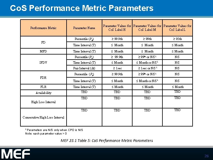
Co. S Performance Metric Parameters Performance Metric Parameter Name FD MFD IFDV FDR FLR Availability Parameter Values for Co. S Label H Co. S Label M Co. S Label L Percentile (Pd) 99. 9 th 95 th Time Interval (T) £ Month £ Month Percentile (Pv) 99. 9 th 99 th or N/S 1 N/S Time Interval (T) £ Month or N/S 1 N/S Pair Interval (Dt) 1 sec or N/S 1 N/S Percentile (Pr) 99. 9 th 99 th or N/S 1 N/S Time Interval (T) £ Month or N/S 1 N/S Time Interval (T) TBD £ Month TBD TBD TBD High Loss Interval Consecutive High Loss Interval 1 Parameters are N/S only when CPO is N/S Note: each parameter value > 0 MEF 23. 1 Table 5: Co. S Performance Metric Parameters 26
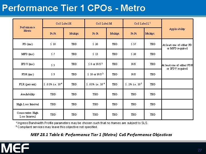
Performance Tier 1 CPOs - Metro Co. S Label H Performance Metric Co. S Label M Co. S Label L 1 Applicability Pt-Pt Multipt FD (ms) £ 10 TBD £ 20 TBD £ 37 TBD MFD (ms) £ 7 TBD £ 13 TBD £ 28 TBD IFDV (ms) £ 3 TBD £ 8 or N/S 2 TBD N/S TBD FDR (ms) £ 5 TBD £ 10 or N/S 2 TBD N/S TBD FLR (percent) £. 01% i. e. 10 -4 TBD £. 1% i. e. 10 -3 TBD Availability TBD TBD TBD High Loss Interval TBD TBD TBD Consecutive High Loss Interval TBD TBD TBD At least one of either FD or MFD required At least one of either FDR or IFDV required 1 Ingress Bandwidth Profile parameters may be chosen such that no frames are subject to SLS. 2 Compliant services may leave this objective not specified. MEF 23. 1 Table 6: Performance Tier 1 (Metro) Co. S Performance Objectives 27
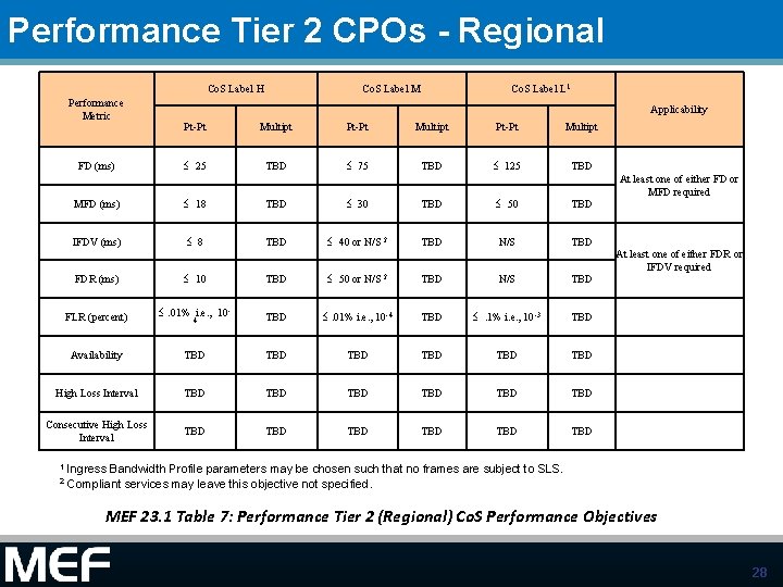
Performance Tier 2 CPOs - Regional Co. S Label H Performance Metric FD (ms) Co. S Label M Co. S Label L 1 Applicability Pt-Pt Multipt £ 25 TBD £ 75 TBD £ 125 TBD At least one of either FD or MFD required MFD (ms) £ 18 TBD £ 30 TBD £ 50 TBD IFDV (ms) £ 8 TBD £ 40 or N/S 2 TBD N/S TBD At least one of either FDR or IFDV required FDR (ms) £ 10 TBD £ 50 or N/S 2 TBD N/S TBD FLR (percent) £. 01% i. e. , 104 TBD £. 01% i. e. , 10 -4 TBD £. 1% i. e. , 10 -3 TBD Availability TBD TBD TBD High Loss Interval TBD TBD TBD Consecutive High Loss Interval TBD TBD TBD 1 Ingress Bandwidth Profile parameters may be chosen such that no frames are subject to SLS. 2 Compliant services may leave this objective not specified. MEF 23. 1 Table 7: Performance Tier 2 (Regional) Co. S Performance Objectives 28
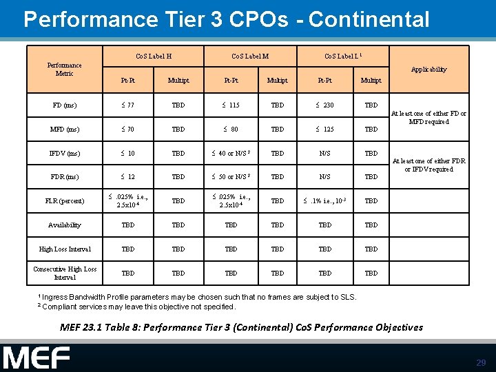
Performance Tier 3 CPOs - Continental Co. S Label H Performance Metric FD (ms) Co. S Label M Co. S Label L 1 Applicability Pt-Pt Multipt £ 77 TBD £ 115 TBD £ 230 TBD At least one of either FD or MFD required MFD (ms) £ 70 TBD £ 80 TBD £ 125 TBD IFDV (ms) £ 10 TBD £ 40 or N/S 2 TBD N/S TBD At least one of either FDR or IFDV required FDR (ms) £ 12 TBD £ 50 or N/S 2 TBD N/S TBD FLR (percent) £. 025% i. e. , 2. 5 x 10 -4 TBD £. 1% i. e. , 10 -3 TBD Availability TBD TBD TBD High Loss Interval TBD TBD TBD Consecutive High Loss Interval TBD TBD TBD 1 Ingress Bandwidth Profile parameters may be chosen such that no frames are subject to SLS. 2 Compliant services may leave this objective not specified. MEF 23. 1 Table 8: Performance Tier 3 (Continental) Co. S Performance Objectives 29
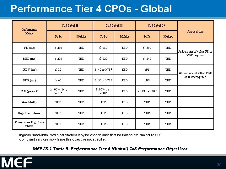
Performance Tier 4 CPOs - Global Co. S Label H Performance Metric FD (ms) Co. S Label M Co. S Label L 1 Applicability Pt-Pt Multipt £ 230 TBD £ 250 TBD £ 390 TBD At least one of either FD or MFD required MFD (ms) £ 200 TBD £ 220 TBD £ 240 TBD IFDV (ms) £ 32 TBD £ 40 or N/S 2 TBD N/S TBD At least one of either FDR or IFDV required FDR (ms) £ 40 TBD £ 50 or N/S 2 TBD N/S TBD FLR (percent) £. 05% i. e. , 5 x 10 -4 TBD £. 1% i. e. , 10 -3 TBD Availability TBD TBD TBD High Loss Interval TBD TBD TBD Consecutive High Loss Interval TBD TBD TBD 1 Ingress Bandwidth Profile parameters may be chosen such that no frames are subject to SLS. 2 Compliant services may leave this objective not specified. MEF 23. 1 Table 9: Performance Tier 4 (Global) Co. S Performance Objectives 30
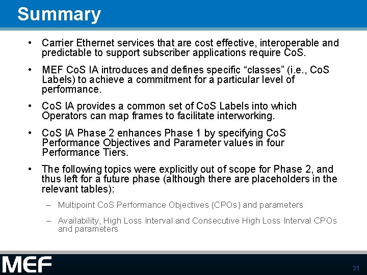
Summary • Carrier Ethernet services that are cost effective, interoperable and predictable to support subscriber applications require Co. S. • MEF Co. S IA introduces and defines specific “classes” (i. e. , Co. S Labels) to achieve a commitment for a particular level of performance. • Co. S IA provides a common set of Co. S Labels into which Operators can map frames to facilitate interworking. • Co. S IA Phase 2 enhances Phase 1 by specifying Co. S Performance Objectives and Parameter values in four Performance Tiers. • The following topics were explicitly out of scope for Phase 2, and thus left for a future phase (although there are placeholders in the relevant tables): – Multipoint Co. S Performance Objectives (CPOs) and parameters – Availability, High Loss Interval and Consecutive High Loss Interval CPOs and parameters 31
Backup Material 32
Informative Examples/Use Cases 33
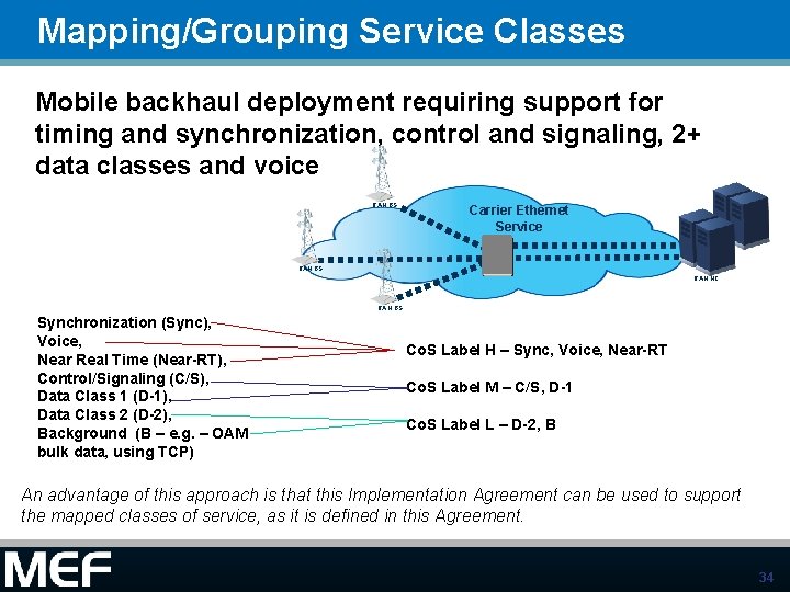
Mapping/Grouping Service Classes Mobile backhaul deployment requiring support for timing and synchronization, control and signaling, 2+ data classes and voice RAN BS Carrier Ethernet Service RAN BS RAN NC RAN BS Synchronization (Sync), Voice, Near Real Time (Near-RT), Control/Signaling (C/S), Data Class 1 (D-1), Data Class 2 (D-2), Background (B – e. g. – OAM bulk data, using TCP) Co. S Label H – Sync, Voice, Near-RT Co. S Label M – C/S, D-1 Co. S Label L – D-2, B An advantage of this approach is that this Implementation Agreement can be used to support the mapped classes of service, as it is defined in this Agreement. 34
PCP and DSCP Mapping • Full mapping of PCP or DSCP values at a UNI is required in 10. 2 to ensure that customer frames are not inadvertently discarded and to simplify configuration of customer equipment – It is allowed to define a specific class for discarding frames intentionally. • Co. S IA provides an informative full mapping examples when only MEF Co. S Labels are present 35
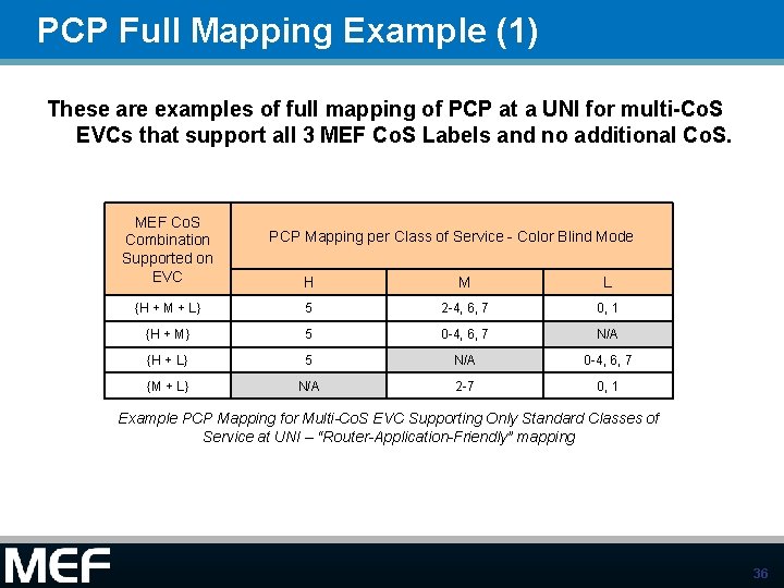
PCP Full Mapping Example (1) These are examples of full mapping of PCP at a UNI for multi-Co. S EVCs that support all 3 MEF Co. S Labels and no additional Co. S. MEF Co. S Combination Supported on EVC PCP Mapping per Class of Service - Color Blind Mode H M L {H + M + L} 5 2 -4, 6, 7 0, 1 {H + M} 5 0 -4, 6, 7 N/A {H + L} 5 N/A 0 -4, 6, 7 {M + L} N/A 2 -7 0, 1 Example PCP Mapping for Multi-Co. S EVC Supporting Only Standard Classes of Service at UNI – “Router-Application-Friendly” mapping 36
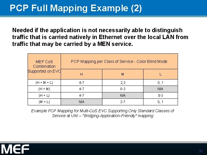
PCP Full Mapping Example (2) Needed if the application is not necessarily able to distinguish traffic that is carried natively in Ethernet over the local LAN from traffic that may be carried by a MEN service. MEF Co. S Combination Supported on EVC PCP Mapping per Class of Service - Color Blind Mode H M L {H + M + L} 4 -7 2, 3 0, 1 {H + M} 4 -7 0 -3 N/A {H + L} 4 -7 N/A 0 -3 {M + L} N/A 2 -7 0, 1 Example PCP Mapping for Multi-Co. S EVC Supporting Only Standard Classes of Service at UNI – “Bridging-Application-Friendly” mapping 37
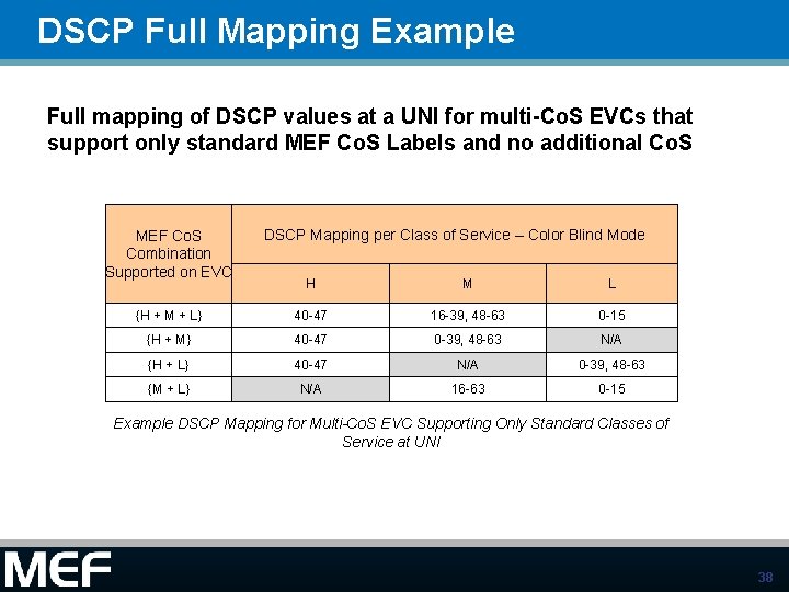
DSCP Full Mapping Example Full mapping of DSCP values at a UNI for multi-Co. S EVCs that support only standard MEF Co. S Labels and no additional Co. S MEF Co. S Combination Supported on EVC DSCP Mapping per Class of Service – Color Blind Mode H M L {H + M + L} 40 -47 16 -39, 48 -63 0 -15 {H + M} 40 -47 0 -39, 48 -63 N/A {H + L} 40 -47 N/A 0 -39, 48 -63 {M + L} N/A 16 -63 0 -15 Example DSCP Mapping for Multi-Co. S EVC Supporting Only Standard Classes of Service at UNI 38
Accelerating Worldwide Adoption of Carrier-class Ethernet Networks and Services www. MEF. net 39
MEF BWP Algorithm Diagrams— 1 of 2 These two diagrams are from Ralph Santitoro’s white paper “Bandwidth Profiles for Ethernet Services. pdf” 40
MEF BWP Algorithm Diagrams— 2 of 2 This diagram of the existing MEF 10. 1 BWP algorithm is from Norival Figueira’s preso “Hierarchical BWP Algorithm Strict Priority. pdf” (BWP folder, ~9/2/2011) 41