Integration of Heat and Power HEAT ENGINES RESERVIOR


- Slides: 32

Integration of Heat and Power

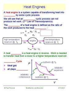
HEAT ENGINES RESERVIOR T 1 Q 1 Heat Engine W Q 2 RESERVIOR First Law of Thermodynamics W = Q 1 - Q 2 Second Law of Thermodynamics W 7 c Q 1 where T -T 7 c = 1 2 T 1 T 2

HEAT PUMPS RESERVIOR T 1 Q 1 Heat Pump W Q 2 RESERVIOR First Law of Thermodynamics Q 1 = W + Q 2 Second Law of Thermodynamics W 7 c Q 1 where T -T 7 c = 1 2 T 1 T 2

F 1(=QHmin) T heat source F 2 Q F 3 F 4 W F 5 Q-W heat sink (F 6) PINCH 0 F 7 F 8 F 9 H = F 1 + Q C = Fn+1 + Q - W F 10 Fn+1(=QCmin)

T HEAT ENGINE O W cold utility (Q-W)=F 1 F 2 hot utility F 3 F 4 F 5 (F 6) PINCH 0 F 7 F 8 F 9 H =Q C = Fn+1 F 10 Fn+1

T F 1 + O F 2 F 3 F 4 F 5 (F 6) PINCH HEAT ENGINE 0 F 7 F 8+(Q-W) F 9+(Q-W) F 10+(Q-W) H =F+Q C = Fn+1 + Q - W Fn+1+(Q-W) W

F 1 T F 2 F 3 F 4 F 5 (F 6) PINCH 0 F 7 F 8 F 9 HEAT ENGINE (d) F 10 O = Fn+1 W (Q-W) H = F 1 C =Q-W

Q Q W W (Q-W) = F 1 T F 2 F 3 F 4 F 5 (F 6) PINCH 0 F 7 F 8 F 9 F 10 Fn+1 (a) (Q-W) H : Q + Q C : Fn+1 + (Q - W)

Q ZERO FLOW T W X 1 F 2 = 0 X 2 F 3 = 0 X 3 F 4 = 0 X 4 F 5 = 0 (F 6) PINCH X 5 0 (= F 1 in (a)) F 7 F 8 F 9 F 10 Fn+1 (b) H : Q C : Fn+1

F 1 - W T F 2 W Q+W F 3 Q F 4 Q W Q F 5 PINCH HEAT PUMP (F 6) 0 F 7 F 8 F 9 F 10 Fn+1 (b) IN : F 1 - W + W OUT : Fn+1

F 1 T F 2 F 3 F 4 F 5 PINCH (F 6) 0 F 7 F 8+Q+W F 9+Q+W F 10 + W Q+W Q Fn+1 + W (b) W HEAT PUMP IN : F 1 + W OUT : Fn+1 + W

T PINCH F 1 (Q+W) F 2 (Q+W) F 3 (Q+W) F 4 (Q+W) F 5 -(Q+W) Q+W (F 6) 0 F 7 Q W Q HEAT PUMP F 8 Q IN : F 1 - (Q+W) = F - Q OUT : Fn+1 - Q F 9 Q F 10 Q Fn+1 + W (c)

Complex Distillation Configurations

(a) A A B C B B C C Figure 5. 1 The direct and indirect sequences of simple distillation columns for a threecomponent separation. (From Smith and Linnhoff, Trans. IChem. E, Ch. ERD, 66: 195, 1988; reproduced by permission of the Institution of Chemical Engineers. )

(b) A B C A B A A B C B Figure 5. 1(續) The direct and indirect sequences of simple distillation columns for a three -component separation. (From Smith and Linnhoff, Trans. IChem. E, Ch. ERD, 66: 195, 1988; reproduced by permission of the Institution of Chemical Engineers. )

A B C A B (Vapor Sidestream) C (a) More than 50% middle component and less than 5% heaviest component. Figure 5. 10 Distillation columns with three products. (From Smith and Linnhoff, Trans. IChem. E, Ch. ERD, 66: 195, 1988; reproduced by permission of the Institution of Chemical Engineers. )

A B C A B (Liquid Sidestream) C (b) More than 50% middle component and less than 5% lightest component. Figure 5. 10(續) Distillation columns with three products. (From Smith and Linnhoff, Trans. IChem. E, Ch. ERD, 66: 195, 1988; reproduced by permission of the Institution of Chemical Engineers. )

A B Partial Condenser A B C A B B B C Partial Reboiler C (a) Sequence for three product separation using nonadjacent keys (b) Figure 5. 11 Choosing nonadjacent keys leads to the prefractionator arrangement.

A B Partial Condenser A B C A B B C Partial Reboiler C (a) (b) Prefractionator arrangement Figure 5. 11(續) Choosing nonadjacent keys leads to the prefractionator arrangement.

A B C A COLUMN 1 B C A COLUMN 2 B C B B C C Figure 5. 12 Composition profiles for the middle product in the columns of the direct sequence show remixing effects. (From Triantafyllou and Smith, Trans. IChem. E, part A, 70: 118, 1992; reproduced by permission of the Institution of Chemical Engineers. )

COLUMN TOP COLUMN 1 COLUMN 2 RE-MIXING IN COLUMN 1 COLUMN BOTTOM 0 Mole Fraction of B 1. 0 Figure 5. 12(續) Composition profiles for the middle product in the columns of the direct sequence show remixing effects. (From Triantafyllou and Smith, Trans. IChem. E, part A, 70: 118, 1992; reproduced by permission of the Institution of Chemical Engineers. )

Partial Condenser A B C A B Partial Reboiler C Figure 5. 13 Composition profiles for the middle product in the prefractionator arrangement show that there are no remixing effects. (From Triantafyllou and Smith, Trans. IChem. E, part A, 70: 118, 1992; reproduced by permission of the Institution of Chemical Engineers. )

COLUMN TOP MAIN COLUMN Prefractionator Top Prefractionator Feed PREFRACTIONATOR Sidestream Stage Prefractionator Bottom COLUMN BOTTOM 0 Mole Fraction of B 1. 0 Figure 5. 13(續) Composition profiles for the middle product in the prefractionator arrangement show that there are no remixing effects. (From Triantafyllou and Smith, Trans. IChem. E, part A, 70: 118, 1992; reproduced by permission of the Institution of Chemical Engineers. )

A A B C B 1 3 2 4 C (a) Thermally-coupled direct sequence (b) Figure 5. 14 Thermal coupling of the direct sequence.

A B C 1 A B 3 2 4 C (a) (b) Side-rectifier arrangement Figure 5. 14(續) Thermal coupling of the direct sequence.

A A B C 1 3 2 4 C (a) Thermally-coupled indirect sequence B (b) Figure 5. 15 Thermal coupling of the indirect sequence.

3 A B C A 2 4 1 C (a) B (b) Side-Stripper arrangement Figure 5. 14(續) Thermal coupling of the indirect sequence.

Partial Condenser A A B C B Partial Reboiler C (a) Prefractionator arrangement (b) Figure 5. 17 The thermally coupled prefractionator can be arranged in a single shell.

A Main Column A B C (a) (b) Thermally coupled prefractionator(Petlyuk Column) Figure 5. 17(續) The thermally coupled prefractionator can be arranged in a single shell.

A Main Column A B C (b) B (C) Dividing wall column C Figure 5. 17(續) The thermally coupled prefractionator can be arranged in a single shell.

T A B C A B C 1 C 2 C Figure 5. 18 Relationship between heat load and level in simple and prefractionator sequences. (From Smith and Linnhoff, Trans. IChem. E, Ch. ERD, 66: 195, 1988; reproduced by permission of the Institution of Chemical Engineers. ) H

A A B C T B C 2 C Figure 5. 18(續) Relationship between heat load and level in simple and prefractionator sequences. (From Smith and Linnhoff, Trans. IChem. E, Ch. ERD, 66: 195, 1988; reproduced by permission of the Institution of Chemical Engineers. ) H
 Power triangle diagram
 Forward integration and backward integration
 Vertical integration
 Simultaneous integration and sequential integration
 Chapter 5 two-cycle and four-cycle engines answers
 Sage game engine
 Library book drawing
 Engines link analysis and
 Engines link analysis and
 Troubleshooting small engines
 Siege engines
 Knowledge search engines
 Meta search engines compared
 Open source search engines
 Light vehicle diesel engines
 Propane injection for gas engines
 Different engine layouts
 Whats engine displacement
 Harper industries has $900 million
 Search engine architecture
 Other search engines
 Principle of carburetion
 Information retrieval slides
 Dot search
 Aircraft engines
 Hz121800
 Avaya identity engines
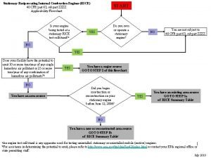
 Reciprocating internal combustion engines rice
 Slatten racing engines
 Search engines information retrieval in practice
 Without rush without engines poetic device
 Automotive engines 8th edition
 Www.sbu
