InputOutput Control IO Control Mechanism mmap function munmap


 • 응용 프로그램에서 특정번지 액세스 – pointer 변수를 이용하여 해당")

 function (2) • Protection mode - PROT_EXEC: page execution PROT_READ: page read 허락")
 usage(1) • munmap() – mmap()과 pair 함수 – Memory mapping을 해제하는 기능 •")
 (1) #include <stdlib. h> #include <unistd. h> #include <sys/mman. h> #include")
 (2) wrtie_data () { ptr=mem_addr 32; ptr=ptr+68; *ptr=0 x 1000 0401;")

 • RAM(0 x 0 c 00 0000)을 액세스하는 프로그램")
 1. SRAM 하드웨어 번지를 정의 : (prgram name: readram)")
 • 8개 SMD 형태의 LED로 구성: 8 bit(1 byte) write 구조")
 • LED Register: 0 x 1060 0000, 8 bits")
 • 4개의 7 segment LED로 구성된 write 구조 – 4개의")
 • BCD-to-7 segment Decoder – Activate signal: positive, negative –")

 • Header file – #define segment 7_L 0 x 10300000")
 int main() { int k; unsigned int low = 0,")

 :")


 function b 10=E, b 9=R/W, b 8=RS")
 • DD RAM address – Text LCD base address:")
 • Text LCD 제어 기능 – – – – –")
 • Control function & Instruction Mode/Code 기 능 제어신호 제어")


 #include <stdlib. h> #include <unistd. h> #include <sys/mman. h> #include")
 int main(int argc, char **argv) { int fd; int i,")
 • Initialization • Screen erase • Cursor control")
- Slides: 48
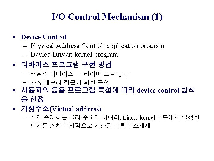
Input/Output Control
목 차 • I/O Control Mechanism – mmap function – munmap function • • RAM Area Access LED Control 4 digits 7 Segment Control Text LCD Control
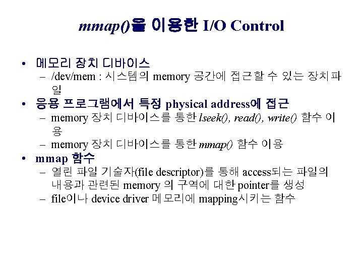
I/O Control Mechanism (2) • 응용 프로그램에서 특정번지 액세스 – pointer 변수를 이용하여 해당 register의 address에 원하는 데 이터를 write하는 programming – 예제) 물리 주소: 0 xf 100 0000, 데이터: 0 xc 0 unsigned char *ptr; ptr = 0 xf 100 0000 /* register physical address */ *ptr = 0 xc 0 /* write data value to register */ – 오류 발생: Linux kernel 에서 물리적 접근을 허가하지 않음, 가상주소를 사용
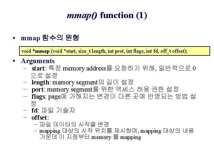
mmap() function (2) • Protection mode - PROT_EXEC: page execution PROT_READ: page read 허락 PROT_WRITE: page write 허락 PROT_NONE: page access 불가 • Flag parameters - MAP_FIXED: 특정한 mapping 위치로 고정 - MAP_SHARED: 다른 프로세스와 mapping 영역의 공유가 가 능 - MAP_PRIVATE: mapping을 설정한 자신만의 mapping 영역의 사용이 가능
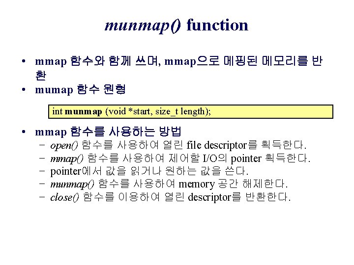
munmap() usage(1) • munmap() – mmap()과 pair 함수 – Memory mapping을 해제하는 기능 • 형식 – #include <unistd. h> – #include <sys/mman. h> – int munmap (void *start, size_t length); • Argument – Start: mmmap()에서 반환했던 가상주소를 대입 함으로서, 해제할 mapping 영역을 공지 – Length: 해제할 때 영역의 길이를 byte 단위로 계산하여 대입 • munmap() Return value – Success: return (0) – Fail: return (-1)
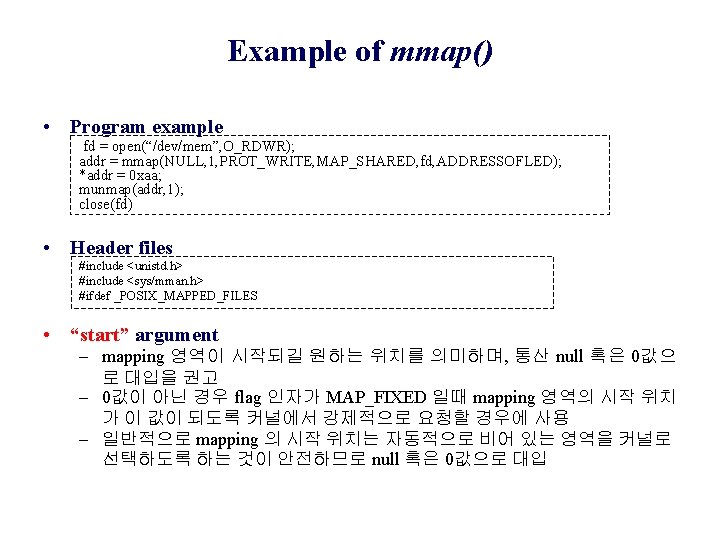
Example of mmap() (1) #include <stdlib. h> #include <unistd. h> #include <sys/mman. h> #include <asm/fcntl. h> int main() { int men_fd; unsigned long *men_add 32, *ptr; if((mem_fd=open(“/dev/mem”, O_RDWR)) < 0){ perrpr(“mem open failn”); exit(2); } } mem_addr 32=mmap(NULL, 1240, (PRO_READ| PROT_WRITE), MAP_SHARED, mem_fd, 0 xff 00 0000); if((int men_add 32 < 0) { mem_addr 32 = NULL; printf(“mmap errorn”); return -1; }
Example of mmap() (2) wrtie_data () { ptr=mem_addr 32; ptr=ptr+68; *ptr=0 x 1000 0401; ptr++; *ptr=0 xf 100 8000; } release_function() { } mummap(mem_add 32, 1024); return 0;
RAM Area Access Control • RAM Area – SRAM 256 Kbytes × 16 bits, 1 Mbytes – Hardware signal: PXA 255 Chip Selection (CS) n. CS 3 – 0 x 0 c 0000 • Diagram
RAM Area Access Program (1) • RAM(0 x 0 c 00 0000)을 액세스하는 프로그램 코딩(readram) – /dev/mem – mmap( , , , 0 x 0 c 0000000) – mumap() • Boot loader 상에서 0 x 0 c 00 0000 번지의 데이터 확인(read) 및 “ 1234568”을 write – read b 32 0 x 0 c 000000 a – write b 32 0 x 0 c 000000 12345678 1. Linux booting 및 RAM access 프로그램 수행 1. EMPOS # boot 2. #. /readsram 3. sram_val: 12345678
RAM Area Access Program (2) 1. SRAM 하드웨어 번지를 정의 : (prgram name: readram) #define ADDRESSOFSRAM 0 x 0 c 00 0000 2. 가상번지를 저장할 변수를 저장하고, open 함수로 fd 설정 unsigned long *addr_sram; fd=open(“/dev/mem", O_RDWR|O_SYNC)) 3. mmap 함수를 이용하여 SRAM 영역의 가상번지를 획득 addr_sram = mmap(NULL, 1, PROT_READ, MAP_SHARED, fd, ADDRESSOFSRAM); 4. 얻은 번지의 내용을 확인하는 코드 삽입 printf("sram_val: [%x]n", *addr_sram); 5. Makefile을 작성하여 컴파일 CC = arm‐linux‐gcc readsram: readsram. c $(CC) $(CFLAGS) ‐o $@ $^ clean: rm ‐f readsram 6. 확인된 내용이 정확한가를 bootloader에서 재확인 EMPOS # read b 32 0 x 0 c 000000 a 7. 로더에서 SRAM 영역에 값을 넣은 후 다시 한번 확인 EMPOS # write b 32 0 x 0 c 000000 12345678 ; ; bootloader에서 해당번지에 데이터를 입력 EMPOS # boot ; ; linux booting #. /readsram ; ; linux에서 해당 번지의 RAM을 접근 sram_val: 12345678
LED Control (1) • 8개 SMD 형태의 LED로 구성: 8 bit(1 byte) write 구조 • 특정번지(0 x 1060 0000)에서 데이터 bit를 출력으로 LED를 on/off 제어 – – fd=open(“/dev/mem”, O_RDRW|O_SYNC) led_addr=mmap(NULL, 1, PROT_WRITE, MAP_SHARED, fd, 0 x 10600000) led_light{ …. *led_addr =0 xaa, delay-fector() …. } munmp(led_addr, 1); • 회로
LED Control (2) • LED Register: 0 x 1060 0000, 8 bits
7 segment Control (1) • 4개의 7 segment LED로 구성된 write 구조 – 4개의 7 segment는 8개의 출력 bit로 구성 – 32 bit CPU 제어를 위해 2개의 7 segment 단위(16 bits)로 제어 – 7 segment LED 정보 지속을 위해 latch 구조 • 회로 7 segment_low =0 x 1030 0000 7 segment_low =0 x 1040 0000
7 segment Control (2) • BCD-to-7 segment Decoder – Activate signal: positive, negative – Display: 0 -1 figures • Code – 1: 0 bc 0 0000 – 2: ab 0 d e 0 g 0 a f b g e c d dp
7 segment LED Data: Cathode type • Cathode type: active High • Table 7 세그먼트 비트 값 표시 데이터 값 dp g f e d c b a 0 0 0 1 1 1 0 x 3 f 1 0 0 0 1 1 0 0 x 06 2 0 1 1 0 x 5 f 3 0 1 0 0 1 1 0 x 4 f 4 0 1 1 0 0 x 66 5 0 1 1 0 1 0 x 6 d 6 0 1 1 1 0 x 7 d 7 0 0 1 1 1 0 x 27 8 0 1 1 1 1 0 x 7 f 9 0 1 1 1 1 0 x 6 f • Program – char Get. Segcode(char x) { … switch(x) …. . }
7 segment Program (1) • Header file – #define segment 7_L 0 x 10300000 – #define segment 7_H 0 x 10400000 • void Showsegment(unsigned int high. Value, unsigned int low. Value) – – – addr_lseg=mmap(NULL, 4, PROT_WRITE, MAP_SHARED, fd, segment 7_L); addr_hseg=mmap(NULL, 4, PROT_WRITE, MAP_SHARED, fd, segment 7_H); *addr_lseg = low. Value; *addr_hseg = high. Value; munmap(addr_lseg, 4); munmap(addr_hseg, 4); • int sizeofword(char *word) • char Getsegcode(char x){ … switch(x) …. . }
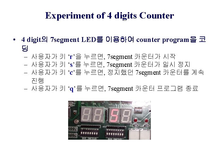
7 segment Program (2) int main() { int k; unsigned int low = 0, high = 0; char data[5]; strcpy(data, "0000"); k = sizeofword(data); switch(k) { case 1: low = Getsegcode(data[0]); break; case 2: low = Getsegcode(data[0]); low = (low<<8) | Getsegcode(data[1]); break; case 3: high = Getsegcode(data[0]); low = Getsegcode(data[1]); low = (low<<8) | Getsegcode(data[2]); break; case 4: high = Getsegcode(data[0]); high = (high<<8) | Getsegcode(data[1]); low = Getsegcode(data[2]); low = (low<<8) | Getsegcode(data[3]); break; default : break; } showsegment(high, low); exit(0); }
Text LCD module • Text LCD – 최대 가로로 쓰여지는 문자 수와 세로로 표시되는 줄 수로 규격 – 열과 행을 구동하는 LCD driver와 이를 제어하는 LCD controller로 구성: Text LCD모듈은 8 bit microprocessor가 내장되어 있고, 2개의 레지스터가 존재 – 20 2(4), 16 2(4), 24 2(4), 14 2(4) size • Signals: 14 pins – Data: byte, DB 0 – DB 7 – Control: R/W, RS (Register Select), E (Enable) – Power: GND (Vss), Vcc, Vo (LCD contrast) Signals (pin) Display (back light)
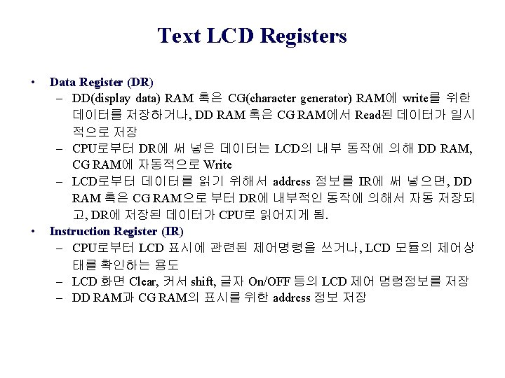
Text LCD module 제어 방법 • Text LCD Registers – Instruction Register (IR) : Text LCD 모듈의 환경설정 – Data Register (DR) : Text LCD 모듈에 글자를 표시하기 위한 데이터 값이 들어가는 레지스터 • Text LCD를 사용방법 – Instruction Register (IR)에 명령을 set – Data Register (DR)에 표시하고자 하는 데이터 값을 write • Text LCD 모듈 접속회로 설계방법 – Text LCD의 data line은 8 bit, control bit가 3 bit이므로 디바이 스 드라이버에서는 하위 8 bit는 data line으로 묶고, 상위 3 bit 는 control line(R/W, RS, E)으로 사용
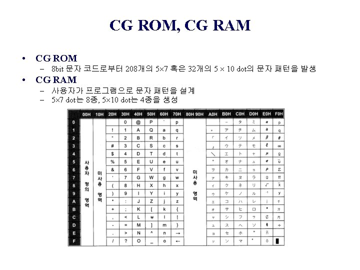
Text LCD Functions • 4/8/32 bits microprocessor와 인터페이스 • 디스플레이 dot resolution: 5 8, 5 10 dots • 80 8 bits의 display data RAM: Display Data RAM에 최대 80 문자 저장 가능) • 240 문자 font 를 위한 문자 발 생 기 ROM(Character Generator ROM) • 64 8 bits 문자 발생기 CG RAM • DC 5 volt 단일 전원과 LCD Contrast Control Power LCD segment Driver RS=1 IN/OUT Buffer RS=0 LCD segment Driver Data Register(DR) Instruction Register(IR) Microprocessor Interface RS R/W E D 0 D 7 5 V GND
Text LCD Block Diagram • Block diagram
Text LCD I/F Circuit • Circuit
Register Section • Register 선택: RS, R/W signal 사용 RS R/W action 0 0 - IR 선택, 제어명령 쓰기(display clear, etc) 0 1 - DB 7로부터 Busy Flag를 읽기 - address counter를 DB 0 -DB 6으로 읽기 1 0 - DB 선택하여 데이터 값을 쓰기(DR에서 DD RAM CG RAM으로) 1 1 - DB 선택하여 데이터 값을 읽어오기(DD RAM/ CG RAM에서 DR로)
setcommand • Void secommand (unsigned short command) function b 10=E, b 9=R/W, b 8=RS 0 0 0 xxxx 1 0 0 xxxx 0 0 0 xxxx – RS=0, R/W=0 : IR selection and write instruction data value – E=0 : E=low/E=high/E=low ---> activation
BF, AC, DD RAM (2) • DD RAM address – Text LCD base address: 0 x 1070 0000 – DDRAM address = base address + 1 st/2 nd column address
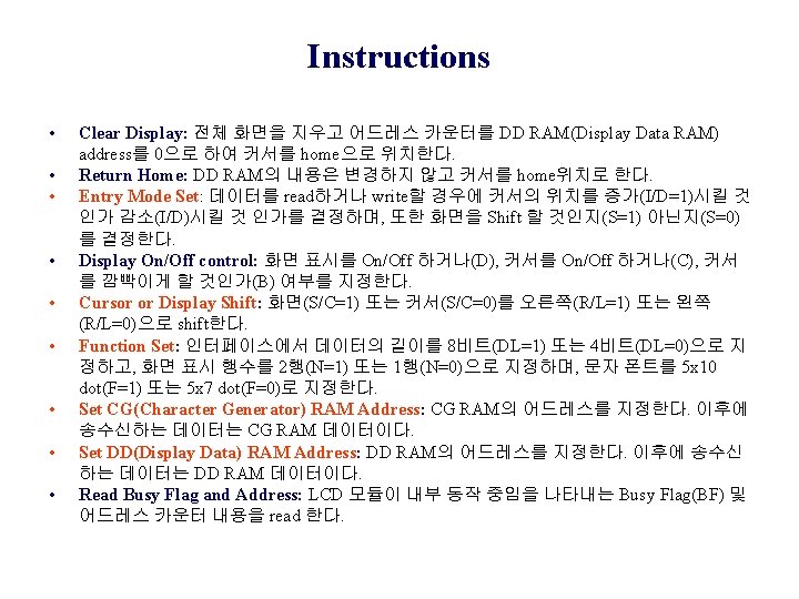
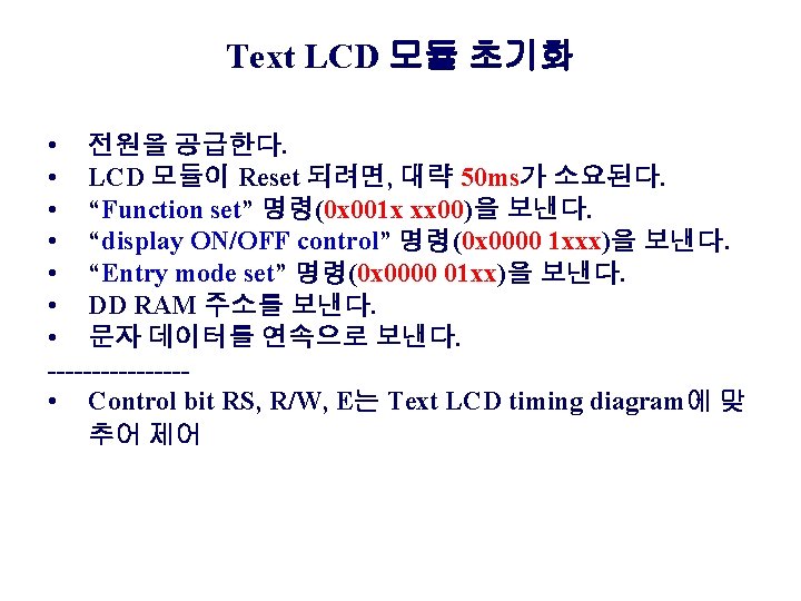
Text LCD Control Functions(1) • Text LCD 제어 기능 – – – – – Clear display Cursor Return home Entry Mode Set Display ON/OFF Control Cursor Display Shift Function Set: Initialization CG RAM Address Set, DD RAM Address Set Busy Flag/Address Read CG RAM/DD RAM으로 데이터 Write와 Read • 제어 신호: RS, R/W, DB 0 -DB 7, E
Text LCD Control Functions(2) • Control function & Instruction Mode/Code 기 능 제어신호 제어 명령 실행시간 RS R/W D 7 D 6 D 5 D 4 D 3 D 2 D 1 D 0 Clear Display 0 0 0 0 0 1 1. 64 ms Return Home 0 0 0 0 1 0 1. 64 ms Entry Mode Set 0 0 0 0 1 I/D S 40 us Display On/Off control 0 0 0 1 D C S 40 us Cursor or Display Shift 0 0 0 1 S/C R/L 0 0 40 us Function Set 0 0 1 D/L N F 0 0 40 us Set CG RAM Address 0 0 0 1 Set DD RAM Address 0 0 1 DD RAM Address 40 us Read Busy Flag and Address 0 1 BF Address Counter 0 us Data Write to CG RAM or DD RAM 1 0 Write Address 40 us Data Read to CG RAM or DD RAM 1 1 Read Address 40 us CG RAM Address 40 us
Read Timing Diagram • R/W 신호가 인가된 후, E 신호가 activate 된 후에 40 ns 후 에 data line에 valid data 신호가 인가 Active edge
Write Timing Diagram • Write Timing • Code b 10=E, b 9=R/W, b 8=RS 0 0 1 1 0 0 1
Text LCD Program (1) #include <stdlib. h> #include <unistd. h> #include <sys/mman. h> #include <asm/fcntl. h> #include <stdio. h> #define ADDRESSOFTEXTLCD 0 x 10700000 void setcommand(unsigned short command); void initialize_textlcd(); void setcommand(unsigned short command); void writebyte(char ch); void initialize_textlcd(); void write_string(char *str, int length); int function_set(int rows, int nfonts); int display_control(int display_enable, int cursor_enable, int nblink); int cusrsor_shit(int set_screen, int set_rightshit); int entry_mode_set(int increase, int nshift); int return_home(); int clear_display(); int set_ddram_address(int pos); unsigned int *p. Textlcd;
Text LCD Program (2) int main(int argc, char **argv) { int fd; int i, len 1=11, len 2=19; char buf 1[100] = "Wellcome to"; char buf 2[100] = "the Embedded World!"; if(argc == 2) { len 1 = strlen(argv[1]); len 2 = 0; strcpy(buf 1, argv[1]); }else if(argc >= 3) { len 1 = strlen(argv[1]); len 2 = strlen(argv[2]); strcpy(buf 1, argv[1]); strcpy(buf 2, argv[2]); } if ((fd=open("/dev/mem", O_RDWR|O_SYNC)) < 0){ perror("mem open failn"); exit(1); } p. Textlcd=mmap(NULL, 4, PROT_WRITE, MAP_SHARED, fd, ADDRESSOFTEXTLCD); if((int)p. Textlcd < 0){ p. Textlcd=NULL; close(fd); printf("mmap errorn"); return ‐ 1; } initialize_textlcd(); for(i=0; i<len 1; i++) writebyte(buf 1[i]); set_ddram_address(0 x 40); for(i=0; i<len 2; i++) writebyte(buf 2[i]); munmap(p. Textlcd, 4); close(fd); }
Text LCD Program (3) • Initialization • Screen erase • Cursor control