Injection Molding Machine 1 Injection unit Screw check


")


 Clamping force F(clamping force) >= P(cavity pressure) * A(projected area) where, P :")
 Mold closing • 금형 clamping • Molding 조건 확립 Injection")


")


 of the material Influence Weight, dimensional")
 Vol. Shrk Packing time Cooling time Vol. Shrk")

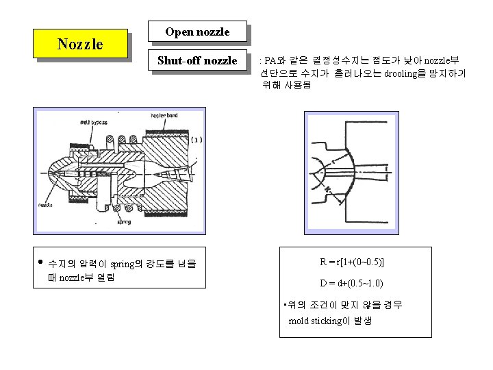
 Purpose : 수지가 Nozzle부 선단으로 drooling되는 것을 방지 Suck")


- Slides: 32
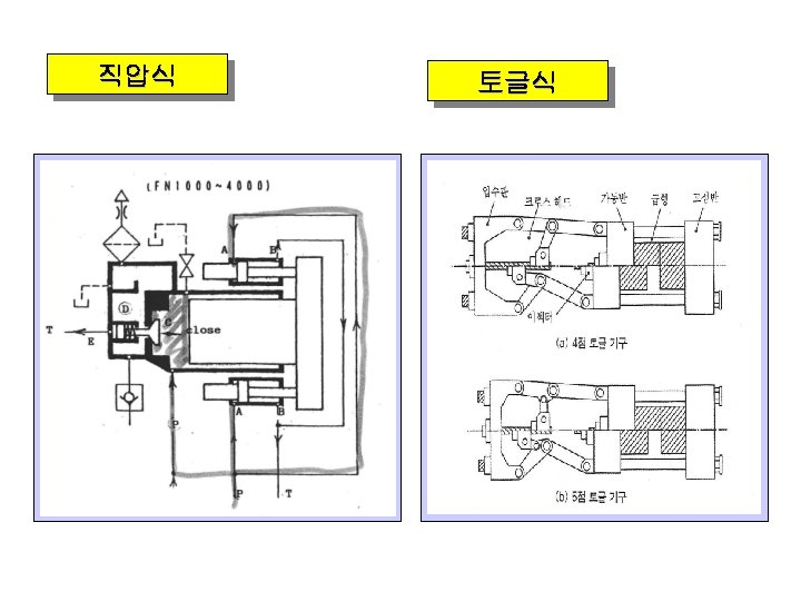
Injection Molding Machine 1. Injection unit Screw, check valve, nozzle, heater bands and hopper 2. Clamping unit 직압식, 토글식, 전동식 3. Drive system Oil pump 등 4. Control system 제어판
Pressure switch의 작동원리 • PS-1 : Clamping pressure increase confirmation • PS-2 : Nozzle touch pressure increase confirmation • Spring의 강도 : 100 kgf/cm 2 • PS-2가 작으면 사출시 노즐이 뒤로 밀린다 Mold closing, opening 의 원리 • Mold opening의 작동원리는 반대로 작동
Screw Design A • Cylinder, screw material : 34 cr. Al. Ni 7(gas nitrided) • L/D = 15~20 • Compression ratio = 2~3 • A: Clearance between ring valve and cylinder ; 0. 02~0. 05 mm • Ring valve의 위치에 따라 사출과 계량이 결정됨 • Cusion양이 일정하지 않을 경우, ring valve의 파손에 의해 back flow가 발생할 수 있슴
Cylinder Temperature Setting A B C • A: High viscous & heat sensitive resin; PC, PMMA • C: Low viscous & heat stable resin; PE, PP • B: Middle viscosity & sensitivity; ABS • D: More heat needed to melt X-line structure; PA • Sometimes, three region’s(rear, middle, front) temperatures are same • Hopper throat temperature range : 40 ~80 C D
Specification Injection pressure Pi Ds L • • Di P, Q Plasticizing capacity P. C. = extruded amount of material/rotation Pi: screw선단에서 받는 압력 * RPM * 60(min) = catalog value * efficiency Injection capacity • • G=C*P*E Injection rate where, G is shot weight P is density E is efficiency of non-return value •
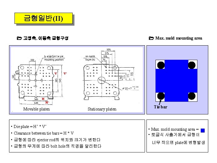
금형일반(I) Clamping force F(clamping force) >= P(cavity pressure) * A(projected area) where, P : 수지마다 다른값을 가짐 A: 성형품, runner, gate의 면적을 모두 포함 Max. daylight opening Movable plate Stationary plate Clamp stroke >= (daylight opening - mold thickness) Clamp stroke >= 2 * (part depth) Maximum daylight opening Max. daylight opening > 2*(part depth) + mold thickness Mold clamping stroke Min. mold thickness
Molding Cycle Sequence(one cycle) Mold closing • 금형 clamping • Molding 조건 확립 Injection • Cavity 충진 • 보압 절환 위치 설정 Cooling, Pasticizing • Back pressure작동 • Gate sealing Holding pressure • Shrinkage 보완 Mold opening, Product remove • Ejector system 작동
Molding : 금형을 사출기에 mounting시 위치설정 V P Mold closing Mold opening P V LS-4 LS-8 LS-4 : Mold 최대 opening위치. Ejector system 작동 LS-8 : Opening시 속도 감소위치 LS-2 : Closing시 tie bar직전에서 속도 감소위치 LS-3 : High-pressure전환 위치, PS-1 switch LS-2 LS-3
Machine Start Power switch • Main power, Heater power • Oil cooler, cooling water Safety device Pump motor starting • Safety door close • Emergency stop 등 확인 • Inching(Jogging) : 기포제거 • Pump oil의 온도 : 30~50도가 적정 성형조건 설정 • Molding 조건, 성형조건, 온도조건 설정 Operation • Screw cold start delaying timer 작동 : setting 온도보다 20도 아래 온도에서 20분 대기
Process Control Check ring Purging Main Body Screw main body Check ring, torpedo Temperature 결정성 수지 = Tm + 10~20 °C 비정형 수지 = Tf + 10~20 °C ( Tf = Tg + 50~60 °C ) Pressure Max. pressure사용. Back pressure는 사용하지 않는다 Speed Main body 쪽은 고속으로 공사출. 때로는 배압을 높여 이물질이 섞여 나오는지 확인 Resin Tf Tg Tm HDPE 134 PP 165~170 PC 240 GPPS ABS PMMA 150 100 150~160 100~110 160 100
Speed • A: Flow mark, short shot • B: Good • C: Gate mark(cloudy) • D: Melt fracture A B C Slow D E Fast Injection Speed • E: Jetting, burning, silver streak, flash
Ultra-high speed Injection Molding
• Filling process : Injection speed를 구현하기 위한 최소값 • Pack process : Injection speed가 작으므로 실제 압력값 Pressure Load pressure P 1 P 2, 3 Setting speed = actual speed V Product weight P Primary pressure time Setting Pressure Primary Pressure Injection time Filling time의 변화가 없는 압력
Pressure switch-over Position Purpose : to perform a smooth transition from the filling phase to the holding phase Too Late P Too Early P P Time • 위의 표시와 같이 Pressure Peak가 발생 • Overpacking에 의해 flash발생 Correct Time • Pressure 의 급격한 감소 • sink mark, surface mark등 불량 발생 • 보압 절환위치에서의 smooth transition
Holding Pressure Purpose : to compensate thermal contraction(shrinkage) of the material Influence Weight, dimensional accuracy and internal structure of the molding Safety region G max. Shot weight G Air bubble, sink marks, shrinkage and warpage Gate frozen Time • 게이트 부근에서의 back flow에 의한 무게변화가 끝나는 지점 ; Gate frozen time
1단 보압 다단 보압 Holding time(Pack+Cool) Vol. Shrk Packing time Cooling time Vol. Shrk Max P Med Gate frozen Med P Gate frozen Min Time Gate • 충전 말단과 게이트에서의 압력차 밀도차이 유발 Med Gate • 게이트에서의 압력을 줄여줌에 따른 pressure relaxation 발생 수축율 차이 발생 균일한 밀도, 수축율 변형 발생 억제 효과
Back pressure • Back pressure를 사용하지 않으면 shot size의 변화가 심하다 • 일반적으로 5~15 (kg/cm 2)의 gauge pressure를 사용한다. • 너무 높으면 frictional heating에 의한 degradation ; Gas 유발, material drooling발생 • Glass-fiber가 첨가될 경우에 배압이 높으면 screw와 cylinder의 손상을 유발
Suck Back( Decompression, Pull back) Purpose : 수지가 Nozzle부 선단으로 drooling되는 것을 방지 Suck back이 없을 경우 계량이 끝난 후 nozzle선단에서 material drooling발생 Suck back이 너무 많은 경우 Nozzle부 선단으로 외부의 공기가 들어가 silver line, bubble, burning과 같은 불량이 발생한다
Injection speed Injection Pressure • 압력을 최대로 설정 후 사출속도를 • Injection speed 과정에서 얻은 속도를 변경 구현하기 위한 압력의 최소값을 구한다 • Defect가 발생하지 않는 영역에서 • Primary pressure time의 변화가 완만해지는 Mold flash Speed Product weight Injection time Short shot flow mark Primary pressure time 영역을 적정 최소 압력이라 판단 Product weight 중앙값을 이용 Short shot Pressure
Change over position Holding Pressure • 사출속도와 압력이 결정된 후 보압절환 • Defect가 발생하지 않는 영역에서 중앙값을 위치를 변경하면서 Defect가 발생하지 이용 않는 영역에서 중앙값을 이용 • 일반적으로 3%~5% 위치 Mold flash Position Short shot Weight upper limit Short shot sink mark Mold flash Holding pressure Product weight Filling time Product weight ㅇ