DEFECT IN PLASTIC INJECTION MOULDING PROCESS DEFECT IN


 (B) (A) - Cavity move to top side and slider")


 is a defect in which the")


 is a surface defect that results from")


 5 simple questions")
")
- Slides: 27
DEFECT IN PLASTIC INJECTION MOULDING PROCESS
DEFECT IN PLASTIC INJECTION MOULDING PROCESS In plastic injection molding, the molded part produced are higher potential to have a plastics defects. These defects may be due to: q Part design q Part materials (resin) q Molds design q Molds fabrication process q Molds material q. Machine parameters and others
1. BLACK SPOT/DOT Ø Generally caused by foreign material in the resin, (look like as a contamination), or the presence of dead space in the nozzle. Ø Sometime it also caused by grease at the side pull or lifter mechanism. Countermeasure 1. Clean the screw barrel and nozzle 2. Purging 3. Check the material (plastic resin)
2. BUBLES Ø Also known as voids. Generated inside the molded part, usually due to insufficient mold filling or air trap. Ø Example critical products: Lens, light pipe… Countermeasure 1. Air Vent 2. Sub-Insert 3. Ejector pin
3. BURR/FLASH Ø Also known as fin, consisting of thin, flat projection in regions where polymer melts has flowed into the parting line of the mold. Ø Long production run – burr will become flash Rootcause 1. Parting line no good 2. Low clamping force 3. Injection pressure too high Countermeasure 1. Re-fitting 2. Use appropriate clamping force and Injection pressure
4. MOULD RELEASE FAULT Ø Defect in the molded part due to poor release or improper ejection from the mold. Usually caused by overfilling of mold with polymer melt and/or by insufficient draft/taper in the mold. Defect 1. Pin Mark 2. Drag/Pull Mark Countermeasure 1. Proper polishing 2. Appropriate cooling time 3. Appropriate draft/taper Rootcause 1. Pin Mark q Improper polishing q Unbalanced ejection q Cooling time not enough 2. Drag/Pull Mark q Improper polishing q Draft/taper not enough
DESIGN FOR UNDERCUTS (A) (B) (A) - Cavity move to top side and slider move to right side (B) - Angular pin push the part out from core side 7
5. SHORT-SHOT FAULT Ø Incomplete molded part, with missing portions or members, caused by failure to obtain complete filling of the flow pathways with the polymer melt. Rootcause 1. Too thin 2. Injection pressure not enough 3. Air trap Countermeasure 1. Avoid design too thin 2. Increase injection pressure 3. Sub-Insert
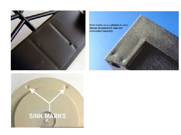
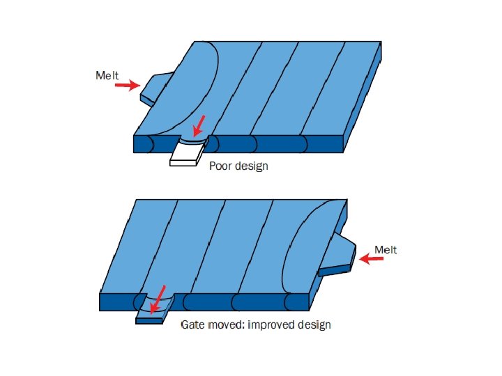
6. SINK MARK Ø Sink marks are indentations on product surfaces. It is the most frequent defect in molding due to volume shrinkage during cooling. This is because it takes time to cool center portion of thick products so that the skin may collapse to create sink marks. Rootcause 1. Part design 2. Injection pressure not enough 3. Holding pressure time not enough 4. Cooling time not enough
7. WELD LINE Ø Form at interface of polymer melt flow from two different pathways. Weld line maybe unacceptable in term of surface appearance or reduced physical strength. Rootcause 1. Part design Countermeasure 1. Air vent 2. Ejector pin 3. Sub-Insert 4. Texturing 5. Increase mould temperature
8. WARPING Ø Warpage is caused by variation in shrinkage throughout the part. Ø Three types of shrinkage effects: q q q Orientation effects Area shrinkage effects Differential cooling effects Rootcause 1. Cooling channel designed 2. Cooling time not enough 3. Part design 4. Imbalanced ejection Orientation and area shrinkage effects Warping caused by differential cooling
9. SILVER STREAKS Ø Gaseous components in the plastic appear at the molding surface and collapse (also called Moisture Mark) Rootcause q Inappropriate drying temperature and time q Air trap
10. BURN MARKS Burn marks are small, dark, or black spots that appear near the end of the molded part’s flow path or in the blind area where an air trap forms. Rootcause q Entrapped Air q Material Degradation
11. DELAMINATION Delamination (sometimes called lamination or layering) is a defect in which the surface of a molded part can be peeled off layer by layer. Rootcause • Incompatible materials blended together • Too much mold release agent being used during the molding process • Low melt temperature in the cavity • Excessive moisture • Sharp corners at the gate and runner
12. DIMENSIONAL VARIATION • Dimensional variation is a defect characterized by the molded part dimension varying from batch to batch or from shot to shot while the machine settings remain the same. Rootcause Dimensional variation can be caused by: • Unstable machine control • A narrow molding window • Improper molding conditions • A broken check ring (within the injection unit) • Unstable material properties
13. DISCOLORATION Discoloration is a color defect characterized by a molded part's color having changed from the original material color. Rootcause This defect can be caused by either material degradation or contamination from the following problems: • The material stays in the barrel too long • The barrel temperature is too high, causing the color to change • Contamination was caused by reground material, different color material, or foreign material
14. FISH EYES • Fish eyes are a surface defect that results from unmelted materials being pushed with the melt stream into the cavity and appearing on the surface of a molded part. Rootcause • Low barrel temperature: If the barrel temperature is too low to melt the materials completely, the unmelted pellets will merge with the melt stream, marring the surface of the part. • Too much regrind: The shape and size of regrind is irregular compared with original material, which can trap more air and cause the material to blend unevenly. • Material contamination: If a high-melt-temperature material is blended into the original material, the blended material may stay in pellet form and cause fish eyes during the molding process. • Low screw rotation speed and back pressure: If the screw rotation speed and the back pressure settings are too low, there might not be enough frictional heating to melt the material completely in the barrel before injection.
15. FLOW MARKS A flow mark or halo is a surface defect in which circular ripples or wavelets appear near the gate. Rootcause Flow marks are caused by cold material near the gate or lack of compensated material during the packing stage. The problem usually can be attributed to: • • Low melt temperature • • Low mold temperature • • Low injection speed • • Low injection pressure • • Small runner stem and gate
16. JETTING • Jetting occurs when polymer melt is pushed at a high velocity through restrictive areas, such as the nozzle, runner, or gate, into open, thicker areas without forming contact with the mold wall. The buckled, snakelike jetting stream causes contact points to form between the folds of melt in the jet, creating small-scale “welds” Problems cause by jetting Jetting leads to part weakness, surface blemishes, and a host of internal defects. Contrast this with a normal filling pattern, in which melt advances in a progressive pattern from the gate to the extremities of the cavity
To solve, use an overlap gate or a submarine gate as shown below.
17. HESITATION Hesitation (or a hesitation mark) is a surface defect that results from the stagnation of polymer melt flow over a thin-sectioned area, or an area of abrupt thickness variation. Hesitation can be eliminated by changing the part thickness or moving the gate location. • When polymer melt is injected into a cavity of variable thickness, it tends to fill the thick and less resistant areas. • As a result, polymer melt may stagnate at thin sections until the rest of the part is filled and the stagnated polymer melt starts moving again (figure above). • However, if the duration of hesitation is significant, polymer will solidify prematurely at the stagnated point. • When the solidified melt front is pushed to the part surface, a surface defect such as a hesitation mark occurs.
Common Defect in Injection Molding Defect Causes Flashing • • • Warping • Non-uniform cooling rate Bubble • To much moisture in material Shot Mold • Air trap • Injection Pressure not enough Sink Mark • Injection Pressure too low • Non-uniform cooling rate Ejector Pin Mark • Cooling time too short • Ejection force too high Injection Pressure too high Clamping force to low Mold fitting not good 24
END
QUIZ 1 • • Next week, Week 7 (27 March 2017) 5 simple questions ½ hour 5% of carry marks
ASSIGNMENT • Individual assignment. 1. Find an actual existing plastic made product (injection moulding) with defect(s). 2. Identify, explain and elaborate the root cause(s). 3. Suggest how to countermeasure the problem(s). • • Pages: min 3 pages : max 5 pages Front page: Download at portal. 5% of carry marks Submission due date : 17 April, before 4 pm