INJECTION MOLDING TECHNIQUE OBJECTIVES VARIOUS MOLDING TECHNIQUES FOR

INJECTION MOLDING & TECHNIQUE

OBJECTIVES VARIOUS MOLDING TECHNIQUES FOR DIFFERENT TYPES OF COMPONENTS ABOUT INJECTION MOLDING MACHINE. ABOUT MOLD FEEDING SYSTEM MOLD FLOW ANALYSIS UNDERCUT AND REMOVAL PROCIDURE PLASTIC PRODUCT DESIGN COMMON DEFECTS IN PLASTICS PARTS

VARIOUS MOLDING TECHNIQUES FOR DIFFERENT TYPES OF COMPONENTS. v. INJECTION MOLDING : I/P & CHILD PARTS, BUMPERS, PILLAR TRIMS. v. EXTRUSION : SEALING SYSTEMS OF AUTOMOBILE, PIPE (PLASTIC & RUBBER) v. BOLW MOLDING : DUCTS , BOTTLES, TOYS. v. THERMO/ VACUUM FORMING : DISPOSABLE CUP & TRAY, v. EXPANDED FOAM MOLDING : STEERING WHEEL, v. ROTATIONAL MOLDING : WATER TANK, SPEARS.

ABOUT INJECTION MOLDING MACHINE.

MAJOR PARTS OF MOLDING MACHINE Clamping& Ejection Unit Injection Unit

DETAIL PARTS OF INJECTION MOLDING MACHINE & THEIR FUNCTION

ABOUT MOULD.

TYPES OF MOLD BASED ON FEEDING SYSTEM • COLD RUNNER MOLD • HOT SPRUE MOLD • HOT RUNNER MOLD BASED ON NUMBER OF PARTS • SINGLE CAVITY MOLD • MULTY CAVITY MOLD BASED MOLD OPENING • 2 PLATE MOLD • 3 PLATE MOLD BASED ON TYPE OF COMPONENT • SINGEL PART MOLD • FAMILY MOLD BASED ON SPECALITY • COINJECTION MOLD • INSERT MOLD
MOLD WILL BE SIMPLE & CHEAP")
BASED ON MOLD OPENING 2 PLATE MOLD ADVANTAGE 1)MOLD WILL BE SIMPLE & CHEAP 2) VARIOUS TYPE OF GATES CAN BE ADOPTED. SINGLE OPENING DISADVANTAGE 1)MOLD WIDTH AND LENGTH WILL BE MORE THAN 3 PLATE MOLD 2) AUTO DEGATING WILL BE POSSIBLE ONLY IN SUBMARRINE GATE FIRST OPENING SECOND OPENING 3 PLATE MOLD ADVANTAGE 1) MOLD SIZE WILL BE LESSER AS THE FEEDING SYSTEM WILL BE ON UPPER PLATE 2) AUTO DEGATING POSSIBLE DISADVANTAGE 1) MORE COSTLY 2) SLOWER PRODUCTION RATE 3) MOLD HEIGHT WILL BE MORE

BASED ON FEEDING SYSTEM HOT SPRUE MOLD Hot Runner Benefits • Faster Cycles - 15 -20% Faster HOT RUNNER MOLD • Eliminates Material Waste - No Sprue or Runners(IN HOT RUNNER SYSTEM) • Improves Part Quality - Less Stress - Better Appearance

SPRUE BUSH MOLD PARTS TOP PLATE GUIDE BUSH` GUIDE PIN CAVITY PLATE SLIDER ASSLY COMPONENT CORE PLATE CORE BACK PLATE RETURN PIN GUIDE BUSH EJECTOR GUIDE PIN SPACER BLOCK BOTTOM PLATE

FEEDING SYSTEM

§ SPRUE -It is the connecting path between machine nozzle & runner system. § RUNNER -It is the connecting path between sprue & gate. § GATE -It is the connecting path between runner and component.

SPRUE • Sprue is the beginning of the melt delivery system within the mold • The interface between the nozzle & the mold • Taper shape has been made for avoiding the back flow of material.

SPRUE PULLER REVERSE TAPER BEST Z PULLER GOOD GROOVE TROUBLESOME

RUNNER SYSTEM A runner system that has been designed correctly will: ·Achieve the optimal number of cavities ·Deliver melt to the cavities ·Balance filling of multiple cavities ·Balance filling of multi-gate cavities ·Minimize scrap ·Eject easily ·Maximize efficiency in energy consumption ·Control the filling/packing/cycle time.

RUNNER BALANCING -FOR UNIFORM FILLING OF COMPONENT -FOR MAINTAINING UNIFORM PRESSURE INSIDE MOLD -REDUCE FILLING TIME A A A A BALANCED RUNNER SYSTEM (CHANGING RUNNER LAYOUT) B A A B UNBALANCED RUNNER SYSTEM (CHANGING RUNNER DIA)

COLD SLUG WELL -Plastic looses its temp during flow through runner. Flow Direction -Cold slug well is provided to accommodate the initial cold material and release behind hot material into cavity. Cold Slug. Well
 gate · Pin gate • Tab")
GATING Manually Trimmed Auto-Ejection Trimmed • Direct (sprue) gate · Pin gate • Tab gate · Submarine (tunnel, chisel) gate • Edge (standard) gate · Hot-runner (hot-probe) gate • Disc/Diaphragm gate · Valve gate • Spoke gate • Fan gate • Film(Flash) gate • Ring gate * The shape of gate will be decided based no the shape & appearance requirement of component.

DIRECT SPRUE GATE Suitable for single cavity large components. Sprue Molded Part

TAB/OVERLAP GATE Suitable for stress free and high optical clarity components. Single Tab Gate 6 in. Max Multiple Tab Gate 12 in. Max Tab Gate Sprue Gate Tab Sprue

EDGE GATE Most commonly used. Land Length 0. 030 Inches Maximum

DISC/DIAPHARGM GATE Runner Sprue Part

Suitable for larger area with thin wall components. FAN GATE RUNNER PART RUNNER GATE LAND

FILM /FLASH GATE Suitable for thin walled flat comopnents. Used for the components required with stress and warpage free. Used for transparent components where flow mark is not allowed. Parallel Runner Gate Runner Parallel Runner

RING GATE Gate Runner Disk Gate Part

PIN POINT GATE 0. 050 0. 020 Land Length 900

SUBMARRINE GATE Molded Parting Line Sprue Zero Land Length Grind Flat on Gate Side, Min. 20 Tunnel Gate Knock Out Pin Fasten Pin Head To Prevent Turning

SUBMARRINE GATE R Gate R

MOLD FLOW ANALYSIS

UNDERCUT AND REMOVAL PROCIDURE

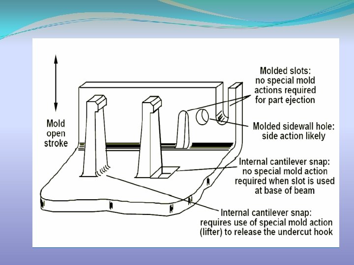
UNDERCUTS ARE THE SHAPES -WHOSE ORIENTATION ARE NOT ALLONG WITH MODLING DIRECTION OF THE ENTIRE PART -LOCATION OF THESE SHPAES WILL BE BELOW PARTING LINE. TYPES OF UNDERCUT • INTERNAL UNDERCUT • EXTERNAL UNDERCUT

TYPES OF UNDERCUT INTERNAL UNDERCUT It can be removed by • Force ejection • Use of collapsible core • Use of lifters • Use of unscrewing mechanism(for threads) SNAP LID INTERNAL THREAD

TYPES OF UNDERCUT EXTERNAL UNDERCUT It can be removed by Side core actuated by • mechanical pins, • Hydrolic &Phumatic cylinders External Thread Detail on Side

TECHNIQUES FOR UNDERCUT REMOVAL CORE CAVITY MATCHING AREA FOR HOLE CORE CAVITY MATCHING

SLIDER MECHANISM COMPONENT SLIDER CORE CAVITY HEEL BLOCK CAM STOPPER PIN

MOLDING DIRECTION SIDE CORE MOVEMENT BY HYDRAULIC CYLINDER Cavity Core Plastic Pin Cored Hole Core Hydraulic Cylinder

LIFTER MECHANISM

PLASTIC PRODUCT DESIGN

BASIC DESIGN CONSIDERATIONS The first requirement is to have a properly modeled part that is fully moldable Sufficiently drafted faces to easily eject the part. No undercuts (will require lifters or sliders) Wall thickness should be uniform(if changing then it has to be gradually for avoiding shrink mark) When creating internal ribs, they should be no greater than 1/3 t of the part’s wall thickness to avoid sink marks on the outside of the part. Drafted faces No draft = difficult to eject

COMMON DEFECTS IN PLASTICS PARTS

• • • Short Shot Flash Weld Lines Ejector Pin Marks Sink Marks

Short Shot Cold material, cold mold, insufficient pressure, non uniform mold temperature, insufficient feed, entrapped air, insufficient external lubrication, insufficient plunger forward time, small gates. Short defect

Flash Material too hot, Inj Pressure too high, High packing pressure, Less clamping force, Poor parting lines or mating surfaces Part w/ Moderate-Heavy Flash

Weld Lines Weld lines is the meeting face of 2 flows coming in opposite direction. Part is weak at Weld line. Can result from poor gate placement Unavoidable areas Gate Weld Line Weld lines occurs if material temperature is low, mold temperature will be improper, improper gate position, improper runner balancing.

Ejector Pin Marks are often left on the part in the area where the ejector pins pushed. Four possible cause: 1) Pin above flush 2) Pin below flush 3) Clearance around pin 4) Improper cooling time 5) Ejection force more. 6) Part sticking.

Sink Marks Sink mark occurs due to abrupt change of thickness. Thickness to be considered for every shape(Rib, Boss, Clip mountings) Minor sink marks can be removed by texturing Thick sections cause sink marks Bad Design Improved Design

Sink mark removed by optimizing the rib thickness to 1/3 t. Sink due to ribs Result after redesigning the Internal Ribs to be 1/3 t or less of the nominal wall thickness

THANK YOU
- Slides: 50