Hard Disk Drives ReadWrite Head Side View Western


![Disk I/O Performance 300 Response Queue [OS Paths] Controller User Thread Time (ms) Disk](https://slidetodoc.com/presentation_image_h2/3ac4236fb5b463daf69c214bc70f6602/image-8.jpg "Disk I/O Performance 300 Response Queue [OS Paths] Controller User Thread Time (ms) Disk")


 RAID Level 2 (Redundancy")
 RAID Level 3 (Bit interleaved")
 block 4 block 5")
 block 0 block 1 block 2 block")
- Slides: 36
Hard Disk Drives Read/Write Head Side View Western Digital Drive http: //www. storagereview. com/guide/ IBM/Hitachi Microdrive
Properties of a Hard Magnetic Disk Sector Platters Track • Properties – Independently addressable element: sector » OS always transfers groups of sectors together—”blocks” – A disk can access directly any given block of information it contains (random access). Can access any file either sequentially or randomly. – A disk can be rewritten in place: it is possible to read/modify/write a block from the disk • Typical numbers (depending on the disk size): – 500 to more than 20, 000 tracks per surface – 32 to 800 sectors per track » A sector is the smallest unit that can be read or written • Zoned bit recording – Constant bit density: more sectors on outer tracks – Speed varies with track location
Disk I/O Performance 300 Response Queue [OS Paths] Controller User Thread Time (ms) Disk Response Time = Queue+Disk Service Time 200 100 0 0% 100% Throughput (Utilization) (% total BW) • Performance of disk drive/file system – Metrics: Response Time, Throughput – Contributing factors to latency: » Software paths (can be loosely modeled by a queue) » Hardware controller » Physical disk media • Queuing behavior: – Can lead to big increases of latency as utilization approaches 100%
Magnetic Disk Characteristic • Cylinder: all the tracks under the head at a given point on all surface Head • Read/write data is a three-stage process: Track Sector Cylinder Platter – Seek time: position the head/arm over the proper track (into proper cylinder) – Rotational latency: wait for the desired sector to rotate under the read/write head – Transfer time: transfer a block of bits (sector) under the read-write head • Disk Latency = Queueing Time + Controller time + Seek Time + Rotation Time + Xfer Time Media Time (Seek+Rot+Xfer) Result • Highest Bandwidth: Hardware Controller Request Software Queue (Device Driver) – Transfer large group of blocks sequentially from one track
Typical Numbers of a Magnetic Disk • Average seek time as reported by the industry: – Typically in the range of 8 ms to 12 ms – Due to locality of disk reference may only be 25% to 33% of the advertised number • Rotational Latency: – Most disks rotate at 3, 600 to 7200 RPM (Up to 15, 000 RPM or more) – Approximately 16 ms to 8 ms per revolution, respectively – An average latency to the desired information is halfway around the disk: 8 ms at 3600 RPM, 4 ms at 7200 RPM • Transfer Time is a function of: – – – Transfer size (usually a sector): 512 B – 1 KB per sector Rotation speed: 3600 RPM to 15000 RPM Recording density: bits per inch on a track Diameter: ranges from 1 in to 5. 25 in Typical values: 2 to 50 MB per second • Controller time depends on controller hardware • Cost drops by factor of two per year (since 1991)
Disk Performance • Assumptions: – Ignoring queuing and controller times for now – Avg seek time of 5 ms, avg rotational delay of 4 ms – Transfer rate of 4 MByte/s, sector size of 1 KByte • Random place on disk: – Seek (5 ms) + Rot. Delay (4 ms) + Transfer (0. 25 ms) – Roughly 10 ms to fetch/put data: 100 KByte/sec • Random place in same cylinder: – Rot. Delay (4 ms) + Transfer (0. 25 ms) – Roughly 5 ms to fetch/put data: 200 KByte/sec • Next sector on same track: – Transfer (0. 25 ms): 4 MByte/sec • Key to using disk effectively (esp. for filesystems) is to minimize seek and rotational delays
Disk Tradeoffs • How do manufacturers choose disk sector sizes? – Need 100 -1000 bits between each sector to allow system to measure how fast disk is spinning and to tolerate small (thermal) changes in track length • What if sector was 1 byte? – Space efficiency – only 1% of disk has useful space – Time efficiency – each seek takes 10 ms, transfer rate of 50 – 100 Bytes/sec • What if sector was 1 KByte? – Space efficiency – only 90% of disk has useful space – Time efficiency – transfer rate of 100 KByte/sec • What if sector was 1 MByte? – Space efficiency – almost all of disk has useful space – Time efficiency – transfer rate of 4 MByte/sec
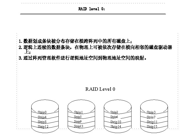
Strip 0 Strip 1 Strip 2 Strip 3 Strip 2 Strip 4 Strip 5 Strip 6 Strip 7 Strip 3 Strip 8 Strip 9 Strip 10 Strip 11 Strip 4 Strip 12 Strip 13 Strip 14 Strip 15 Strip 6 Strip 7 Strip 8 . . . Array Management software Data mapping for a RAID Level 0 Array
Strip 0 Strip 1 Strip 2 Strip 3 Strip 4 Strip 5 Strip 6 Strip 7 Strip 8 Strip 9 Strip 10 Strip 11 Strip 12 Strip 13 Strip 14 Strip 15 RAID Level 1 (Mirrored)
b 0 b 1 b 2 b 3 f 0(b) RAID Level 2 (Redundancy through Hamming Code) f 1(b) f 2(b)
b 0 b 1 b 2 b 3 P(b) RAID Level 3 (Bit interleaved Parity)
block 0 block 1 block 2 block 3 P(0 -3) block 4 block 5 block 6 block 7 P(4 -7) block 8 block 9 block 10 block 11 P(8 -11) block 12 block 13 block 14 block 15 P(12 -15) 90 RAID Level 4 (Block level Parity)
RAID Level 5 (Block level Distributed parity) block 0 block 1 block 2 block 3 P(0 -3) block 4 block 5 block 6 P(4 -7) block 7 block 8 block 9 P(8 -11) block 10 Block 11 block 12 P(12 -15) block 13 block 14 Block 15 block 12