Movinghead Disk Mechanism Rotation Speeds 60 to 200


- Slides: 21

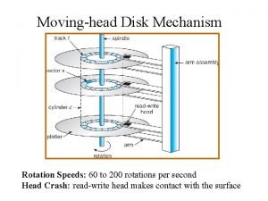
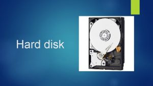
Moving-head Disk Mechanism Rotation Speeds: 60 to 200 rotations per second Head Crash: read-write head makes contact with the surface

Disk Structure • • • Cylinder: the set of tracks that all the heads are currently located at. Track: A ring on a disk where data can be written Sector: The smallest transfer unit of data accessed in a block Cluster: A group of sectors the operating system treats as a unit Organization Choices – Sector mapping (One dimension array of logical blocks) • 0 is first sector, track 0 of the outermost cylinder. • Subsequent sectors map through tracks, through cylinders, in an outer to inner direction. – Sector counts and density • fixed sectors per track: varying densities • Varied sectors per track: outer tracks have more sectors; constant density – Bad block management • Sector sparing: replace bad sectors with spares in the same cylinder • Sector slipping: copy all sectors down to the next spare

Magnetic Tape • • • Early secondary-storage medium of choice Persistent, inexpensive, and has large data capacity Very slow access due to sequential nature Used for backup and for storing infrequently-used data Kept on spools Transfer rates comparable to disk if read write head is positioned to the data • 20 -200 GB are typical storage capacities

Storage Attached to a Host System • Basic: Connections are accessed through I/O ports communicating through busses • Small Computer System Interface (SCSI) protocol – – Connects to sixteen devices One SCI initiator and up to fifteen targets Each target controls up to 8 logical units Logical units can be RAID arrays or a CD jukebox • Fibre Channel (FC) is high-speed architecture – Private high speed switched network to many attached hosts – Storage can be dynamically allocated to each hosts • Other interface Standards: USB, EIDE, ATA

Network-Attached Storage (NAS) • Storage made available over a network • Protocols – NFS is a common protocols – i. SCSI embeds SCSI protocol in IP. • Implementation: remote procedure calls (RPCs)

Storage Area Network • Popular for large storage environments • Private high speed network • Flexible for attaching many hosts to multiple storage arrays

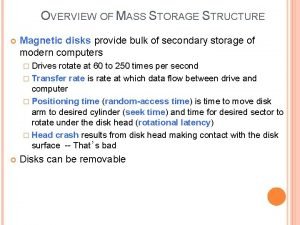
Basic Storage System Concepts • The OS presents a one of two virtual storage abstraction – Raw device: an array of data blocks (a partition). – File system: OS schedules interleaved application requests • Goal: optimize disk access time and throughput • Access time (seek time + rotational latency) – Seek time: moving the heads to the cylinder with the data – Rotational latency: rotate the disk head to the desired sector – Transfer rate: data flow speed between drive and computer – Operating systems attempts to minimize seek time; hardware optimizes rotational latency • Definitions – Throughput: bytes transferred per unit time – Disk bandwidth: total bytes transferred / (time from first request to time of last transfer)

First Come First Serve (FCFS) Service the first request first This Illustration shows a total head movement of 640 cylinders.

Shortest Seek Time First (SSTF) Service the request closest to the current head position • SSTF scheduling is similar to SJF scheduling • Starvation of some requests is possible • This Illustration shows total head movement of 236 cylinders.

SCAN (Elevator) and C-Scan SCAN: Service the first request encountered in the current head direction C-Scan: Services in one direction; SCAN: Services in both directions C-Scan: Return to the beginning after each pass (circular list) Head going left Movement = 236 cylinders Head going right Movement = 382 cylinders • C-Scan: Provides a more uniform wait time than SCAN. • Repositioning to the beginning is faster than repositioning in small pieces because of acceleration and deceleration.

Look and C-Look Similar to SCAN and C-SCAN except don’t go to end of disk on each pass Head going right Movement = 322 cylinders C-Look Algorithm

Which Disk Scheduling Algorithm? • SSTF applies if starvation is not an issue (light loads) • SCAN and C-SCAN perform better with heavy loads • Requests for disk service can be influenced by the file-allocation method • The disk-scheduling algorithm – Normally a separate background running module of the operating system – It can easily be replaced if desired

Disk Management • Factory Low-level formatting – Divide disk into sectors for access by a disk controller • OS Partitioning – Divide disks into separate groups of ‘raw’ cylinders – Sector sparing is a technique to recover from “bad” blocks • User Logical formatting – Initialize the file system MS DOS Structure

Disk Booting in Windows 2000 The ROM bootstrap reads the boot sector, which then proceeds to load the OS

Swap-Space Management • Swap-space: A disk extension of main memory • Implementation can be: – a normal part of the file system (slower but flexible) – in a separate disk partition (faster but less flexible) • Examples – 4. 3 BSD • Allocates swap space when process starts • holds text segment (the code) and data segment – Solaris 2: allocates swap space only when a page is forced to disk

Swap Space Virtual memory extension of main memory BSD Program (Text) Segments BSD Data Segments

Redundant Array of Inexpensive Disks (RAID) • Goal: achieve reliability through redundancy or increase speed through parallelism • Seven Raid Organizations 0: Non-redundant striping: Parts of data stored on different disks. Group of disks acts as a single storage device 1: Mirrored data: stores (shadows) duplicates of each disk 2: Error correction codes: Parity is spread over a group of dedicated disks 3: Bit interleaved parity: Parity is written to a dedicated disk 4: Block interleaved parity: Parity stored on a disk separate from the data 5: Block-interleaved distributed parity: stripes data and parity across the RAID 6: P + Q redundancy: Parity and data are written, both with redundancy Parity: Information to reconstruct data in case of failure

RAID Examples • Top: striped and then mirrored • Bottom: mirrored and then striped

Stable Storage Definition: Storage that carries a “guarantee” of reliability • Transactions and write-ahead logs require stable storage • To implement stable storage: – Replicate information on more than one nonvolatile storage media with independent failure modes. – Update information in a controlled manner to ensure that we can recover the stable data after any failure that happens during data transfer or recovery. – After failure, copy incomplete copies from the media that has successfully completed its operation.

Tertiary (Removable) Storage • Characteristic: Low cost, high capacity • Examples – Removable magnetic disks: nearly as fast as hard disks, but less reliable – A magneto-optic disk: records on rigid platter coated with magnetic material • The read write heads are further from the head, resistant to head crash • lasers used to amplify magnetic material for write and detect – Optical disks: Altered by laser light. Very durable and reliable. – Tape: Falling price gap between tapes and disks, makes these less popular • Hierarchical Storage Management (HSM) – – – Extends primary and secondary storage to include tertiary storage Found in supercomputing centers that have enormous volumes of data Usually implemented as a jukebox of removable disks Disk-resident files are archived to a tape or disk library for low cost storage. Files are automatically staged back (slowly) to disk for active use Note: fixed drives tend to be more reliable than removable ones

Cost Price/Megabyte Hard Disk From 1981 to 2000 Price/MB DRAM From 1981 to 2000 Price/Mb Tape, From 1984 -2000
 100 200 300
 Differentiate between racemic mixture and meso compound
 Disk storage types
 The head of moving head disk with 100 tracks
 Moving head disk mechanism
 Operation of moving head disk storage
 Moving head disk mechanism
 Optical disk
 Mass storage structure
 200 + 200 = 400
 200+200+300+300
 200+200+300
 200 + 200 + 300
 200+200+100+100
 100 200 300
 Wave speeds
 Sound will travel at different speeds in different mediums.
 Wave speeds
 Which macromolecule is this?
 Physical characteristics of a cheetah
 Examples of a medium in waves
 A movie stunt driver on a motorcycle speeds

