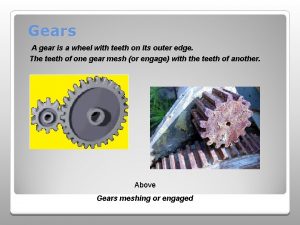
Gears Gears A gear is a wheel with


- Slides: 33

Gears

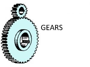
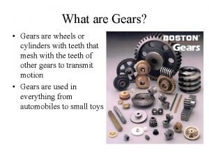
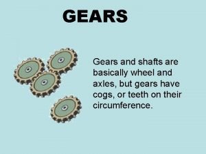
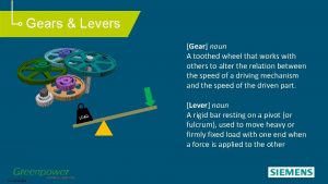
Gears A gear is a wheel with teeth that mesh together with other gears

Gears • A gear is a simple machine like a lever • The larger the diameter of the gear the longer the lever

What are Gears used for? �Ensure positive motion �Reverse the direction of rotation �Increase or decrease the speed of rotation �Change the torque �Change the direction of a power source �Move rotational motion to a different axis �Keep the rotation of two axes synchronized

Terms �Pinion: smaller of a pair of gears �External Gear: teeth formed on the outer surface of a cylinder �Internal Gear: teeth formed on the inner surface of a cylinder

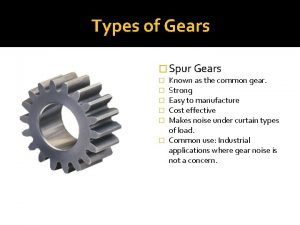
Spur Gear �Most common �Used to transmit power from one shaft to another parallel shaft �Move opposite each other �Driver gear is the gear connected to the motor

Spur Gear Advantages: • Low manufacturing cost • Simple design • Ease of maintenance Disadvantage: • Less load capacity • Higher noise level

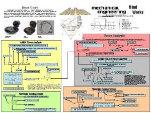
Bevel Gear �Used when two axes intersect at right angles �Changes the direction of drive Disadvantage: • • Gears are designed to work specifically with each other not interchangeable Must be Precisely mounted Spiral Bevel Used: differential drives, hand drills

Rack and Pinion Gear Pinion is the round gear Rack is the flat straight piece � a toothed bar or rod that can be thought of as a sector gear with an infinitely large radius of curvature. � Torque can be converted to linear force by meshing a rack with a pinion: the pinion turns; the rack moves in a straight line. � Such a mechanism is used in automobiles to convert the rotation of the steering wheel into the left-to-right motion of the tie rod(s).

Helical Gear � The leading edges of the teeth are not parallel to the axis of rotation, but are set at an angle. Since the gear is curved, this angling causes the tooth shape to be a segment of a helix. � Helical gears can be meshed in parallel or crossed orientations � The angled teeth engage more gradually than do spur gear teeth, causing them to run more smoothly and quietly. Parallel configuration Cross configuration

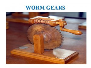
Worm Gear �Worm gears: resemble screws. A worm gear is usually meshed with a spur gear or a helical gear, which is called the gear, wheel, or worm wheel. �Worm-and-gear sets are a simple and compact way to achieve a high torque, low speed gear ratio. �Axles are perpendicular like bevel gears.

Material � Nonferrous alloys � Cast Irons � Power metal � Plastics - is commonly used where cost or weight is a concern. A properly designed plastic gear can replace steel in many cases because it has many desirable properties. including dirt tolerance, low speed meshing, the ability to "skip" quite well and the ability to be made with materials not needing additional lubrication. � Manufacturers have employed plastic gears to reduce costs in consumer items including copy machines, optical storage devices, cheap dynamos, consumer audio equipment, servo motors, and printers. � Steels are most commonly used because of their high strength-to- weight ratio and low cost.

Manufacturing How Gears are Made � Most of all gearing produced worldwide is produced by net shape molding. � Molded gearing is usually either powder metallurgy or plastic molding � Many gears are done when they leave the mold (including injection molded plastic and die cast metal gears), � powdered metal gears require sintering � sand castings or investment castings require gear cutting or other machining to finish them. � The most common form of gear cutting is hobbling, but gear shaping, milling, and broaching also exist. � 3 D printing as a production method is expanding rapidly. � For metal gears in the transmissions of cars and trucks, the teeth are heat treated to make them hard and more wear resistant while leaving the core soft and tough. � For large gears that are prone to warp, a quench press is used.

Gear Standards �American Gear Manufacturers Association - AGMA �organized in 1916 to formulate quality standards for gear inspection to reduce noise from automotive timing gears �in 1993 AGMA assumed leadership of the ISO committee governing international standards for gearing.

Sprocket �Two gears that don’t touch �Driven by a chain �Both sprockets turn the same direction

Sprocket �Examples: �Bikes, machinery, motorcycles, Tracked vehicles, film projectors

Every day Uses of Gears Hand can opener, non digital watch/clock, bike, egg beater, sprocket: movie projector-used in film transport mechanisms, car transmission, drill.

Ratios �

Ratios on drawings - scale down � 1: 1 or full size means: one inch measured on the drawing = one inch on the real part � 1: 2 or one to two - for every one inch measured on the drawing = two inches on the real part�This means to scale down �the part is smaller on the drawing than in real life � 1: 4 or one to four - for every one inch measured on the drawing = four inches on the real part – �This means to scale down �the part is smaller on the drawing than in real life

Ratios on drawings - scale up �We can also scale things to be larger than real size � 2: 1 or two to one - for every two inches on the drawing = one inch on the real part – �scale up the part looks bigger on the drawing than in real life � 4: 1 or four to one – for every four inches on the drawing = one inch on the real part – �Scale up the part – the part looks bigger on drawing than in real life.

Ratio How to write them � The order matters Cats to dogs 10: 15 Dogs to Cats 15: 10

Ratio How to write them �We can also reduce ratios similar to fractions � 10: 15 to 2: 3 or 15: 10 to 3: 2 �We can also compare the total to the parts �Dogs 15, cats 10, total 25 Cats to Total 10: 25 or 2: 5 Dogs to Total 15: 25 or 3: 5

Gear Teeth Advantages �They prevent slippage between the gears - therefore axles connected by gears are always synchronized exactly with one another. �They make it possible to determine exact gear ratios - you just count the number of teeth in the two gears and divide. So if one gear has 60 teeth and another has 20, the gear ratio when these two gears are connected together is 3: 1. �They make it so that slight imperfections in the actual diameter and circumference of two gears don't matter. The gear ratio is controlled by the number of teeth even if the diameters are a bit off.

2 Gears equal teeth �Gears with equal amount of teeth the ratio is 1: 1 Counter Clockwise

Unequal Gear Size �Gears with unequal teeth the ratio is one to another �For example: 1: 2 1: 3 1: 4 or 2: 1 3: 1 4: 1 �For each complete revolution of the large gear �The small gear will revolve more than once depending on the ratio Counter Clockwise Pinion Gear or Driver – input gear Connected to the motor Clockwise Driven-output gear Connected to the wheel

Counter Clockwise Gear Ratios Pinion Gear Driver For example: � 1: 2 Gear A 20 teeth Gear B 10 teeth � 1: 4 Gear A 20 teeth Gear B 5 teeth Clockwise � 2: 1 Gear A 10 teeth Gear B 20 teeth Driven � 3: 1 Gear A 25 teeth Gear B 75 teeth � 4: 1 Gear A 20 teeth Gear B 80 teeth �For each complete revolution of the large gear �The small gear will revolve more than once depending on the ratio �Example 1: 2 the large gear turns once the small one twice

A basic rule of gears When transmit power from a motor to a wheel: The gear connected to motor is driver or input gear The gear connected to the wheel is the driven or output gear (ratio is the number of teeth on each gear) Gear Ratio GR is : output: input or driven: driver Can rewrite as a fraction: GR = output/input = driven/driver

Basic rules of gears �If a gear gives more force get less speed �If get more speed get less force �Small gears driving large gear: torque increases �Large gear driving small gear: torque decreases �Small gear driving big gear: speed decreases �Large gear driving small gear: speed increases

A basic rule of gears When a large gear turns a small gear the speed increases, this is gearing up. small gear turns a large gear the speed decreases, this is gearing down.

Torque �moment of force is the tendency of a force to rotate an object about its axis or pivot mathematically: torque is defined as the cross product of the leverarm distance vector and the force vector, which tends to produce rotation.

Example Problem You are designing an arm with a reach of 0. 4 m lifting a 10 N object. The load on the motor can’t be any more than 0. 803 N-m What gear reduction is required? torque = Force x Distance (force = 10 N distance = 0. 4 m ) Torque = 10 N x 0. 4 m = 4 N-m (output torque) Output torque = input torque x gear reduction (solve for gear reduction) Gear reduction = output torque/input torque (input torque=motor= 0. 803 N-m) Gear reduction = 4 N-m/0. 803 N-m Gear reduction = 4. 981 Given the following gears: 12 -tooth, 36 -tooth, 60 -tooth, and 84 -tooth what combination with work?

Given the following gears: 12 -tooth, 36 -tooth, 60 -tooth, and 84 -tooth what combination with work? (Want 4. 981 answer from other slide) These are the available gear ratios: So two gears 60: 12 will give a reduction of 5 which is closest to 4. 981 Divide first number by the second number

The End
 Are gears wheels?
 Difference between external and internal gear pump
 Equipment used for landscaping
 Ama of block and tackle
 Gear wheel of infinite diameter is also known as
 Chapter 74 ase questions
 Tire wheel and wheel bearing fundamentals
 2 major parts of sewing machine
 How many type of gear
 Gears pulleys and levers
 Reciprocal of velocity ratio
 Cppdepend
 Mechanical reasoning test
 Falling gear
 Vex iq
 Ima of gears
 Evolution of fishing gears
 When equal bevel gears connect two shafts
 Falling gears adalah
 A bicycle chain fits tightly around two gears
 Types of gear
 Gears types
 Vex bevel gear
 Law of gearing
 Charlie chaplin gears
 Are gears wheels
 Mahindra gears
 Gears sprockets pulleys
 Compound machine with 3 simple machines
 Jenis gear
 Sansan gear
 Global hydraulic gear pump market
 Aspect ratio worksheet
 Water powered factories
