
KINEMATICS MEC 2211 OF MACHINERY MODULE 5 GEARS





- Slides: 29
KINEMATICS MEC 2211 OF MACHINERY MODULE 5 GEARS 1
Introduction to Gears • • • Gears are widely used and most important form of mechanical drive Used in many fields and under wide range of conditions From watches and instruments to the heaviest and most powerful machinery.
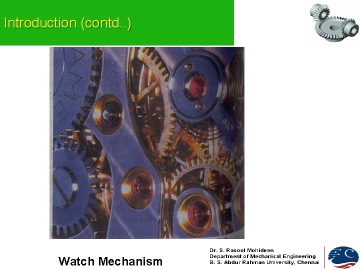
Introduction (contd. . ) Watch Mechanism
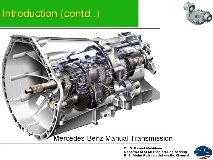
Introduction (contd. . ) Mercedes-Benz Manual Transmission
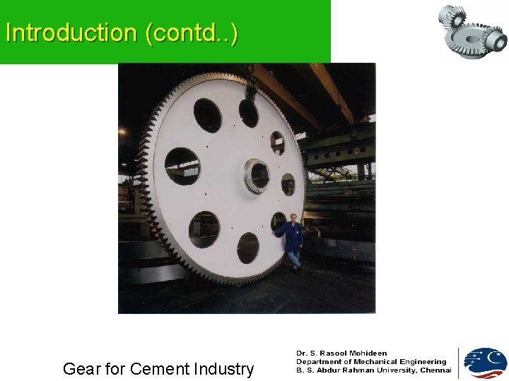
Introduction (contd. . ) Gear for Cement Industry
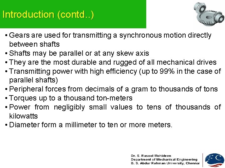
Introduction (contd. . ) • Gears are used for transmitting a synchronous motion directly between shafts • Shafts may be parallel or at any skew axis • They are the most durable and rugged of all mechanical drives • Transmitting power with high efficiency (up to 99% in the case of parallel shafts) • Peripheral forces from decimals of a gram to thousands of tons • Torques up to a thousand ton-meters • Power from negligibly small values to tens of thousands of kilowatts • Diameter form a millimeter to ten or more meters.
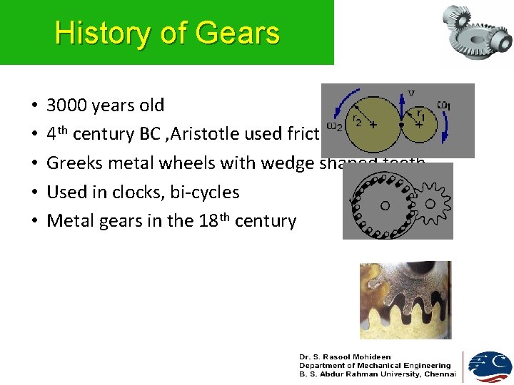
History of Gears • • • 3000 years old 4 th century BC , Aristotle used friction wheels Greeks metal wheels with wedge shaped teeth Used in clocks, bi-cycles Metal gears in the 18 th century
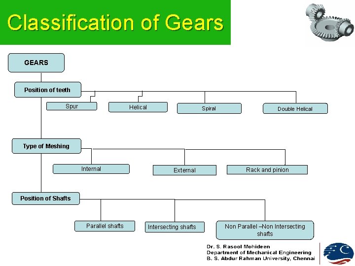
Classification of Gears GEARS Position of teeth Spur Helical Spiral Double Helical Type of Meshing Internal External Rack and pinion Position of Shafts Parallel shafts Intersecting shafts Non Parallel –Non Intersecting shafts
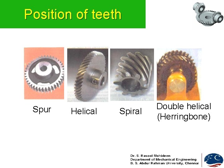
Position of teeth Spur Helical Spiral Double helical (Herringbone)
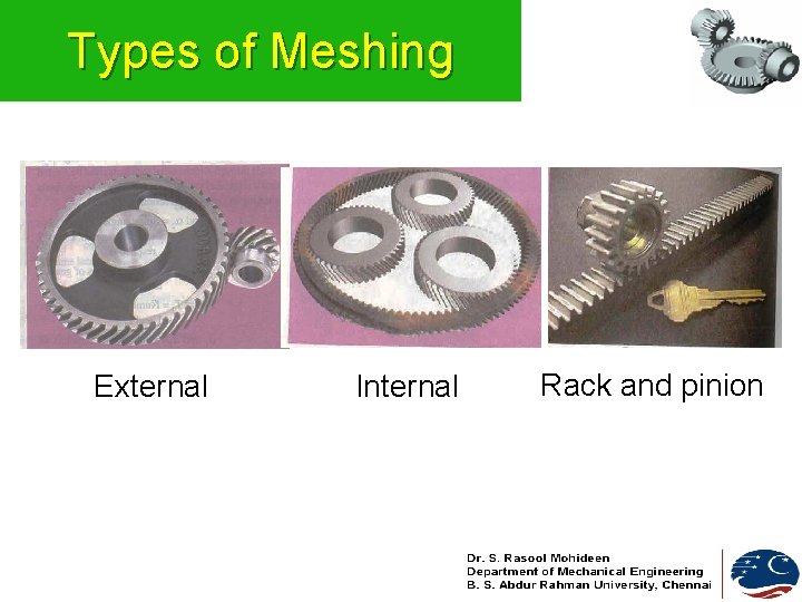
Types of Meshing External Internal Rack and pinion
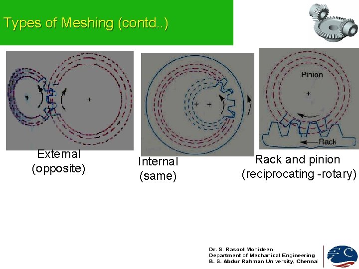
Types of Meshing (contd. . ) External (opposite) Internal (same) Rack and pinion (reciprocating -rotary)
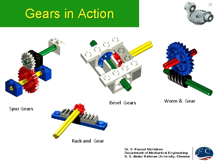
12 Gears in Action Bevel Gears Spur Gears Rack and Gear Worm & Gear
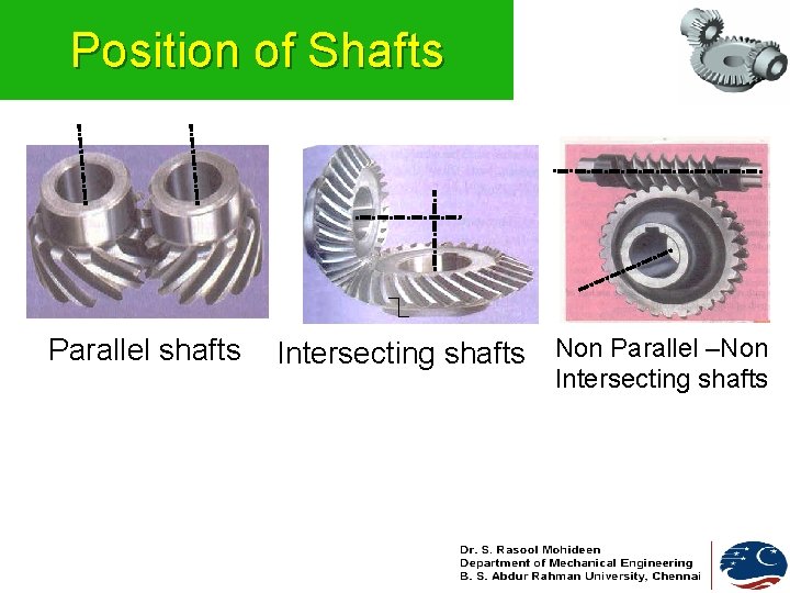
Position of Shafts Parallel shafts Intersecting shafts Non Parallel –Non Intersecting shafts
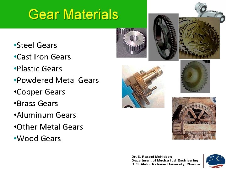
Gear Materials • Steel Gears • Cast Iron Gears • Plastic Gears • Powdered Metal Gears • Copper Gears • Brass Gears • Aluminum Gears • Other Metal Gears • Wood Gears
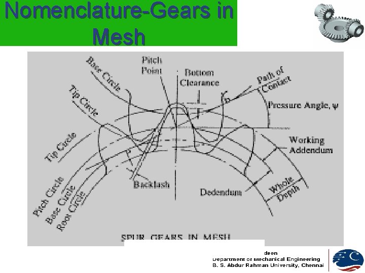
Nomenclature-Gears in Mesh
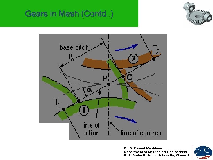
Gears in Mesh (Contd. . )
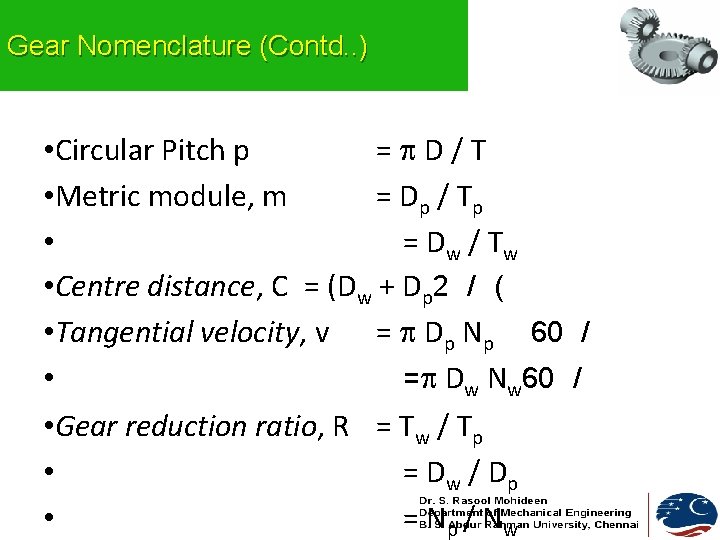
Gear Nomenclature (Contd. . ) • Circular Pitch p = D/T • Metric module, m = Dp / T p • = Dw / T w • Centre distance, C = (Dw + Dp 2 / ( • Tangential velocity, v = Dp Np 60 / • = Dw Nw 60 / • Gear reduction ratio, R = Tw / Tp • = Dw / D p • = Np / Nw
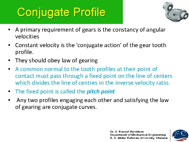
Conjugate Profile • A primary requirement of gears is the constancy of angular velocities • Constant velocity is the 'conjugate action' of the gear tooth profile. • They should obey law of gearing • A common normal to the tooth profiles at their point of contact must pass through a fixed point on the line of centers which divides the line of centres in the inverse velocity ratio. • The fixed point is called the pitch point • Any two profiles engaging each other and satisfying the law of gearing are conjugate curves.
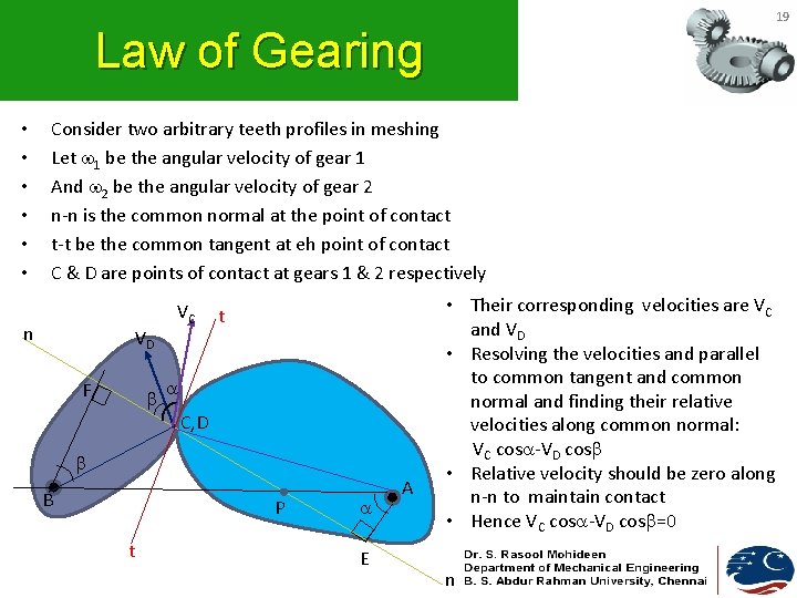
19 Law of Gearing • • • Consider two arbitrary teeth profiles in meshing Let 1 be the angular velocity of gear 1 And 2 be the angular velocity of gear 2 n-n is the common normal at the point of contact t-t be the common tangent at eh point of contact C & D are points of contact at gears 1 & 2 respectively n VD F VC t C, D B P t E A • Their corresponding velocities are VC and VD • Resolving the velocities and parallel to common tangent and common normal and finding their relative velocities along common normal: VC cos -VD cos • Relative velocity should be zero along n-n to maintain contact • Hence VC cos -VD cos =0 n
20 Law of Gearing (Contd. . ) VC cos -VD cos =0 ( 1 X AC X AE/AC )-( 2 X BD X BF/BD )=0 1 AE- 2 BF=0 1/ 2 =BF/AE=BP/AP as BPF and APE are similar Hence 1/ 2 =BP/AP n VD F VC t C, D B P t E • A common normal to the tooth profiles at their point of contact must pass through a fixed point on the line of centers which divides the line of centres in the inverse velocity ratio. • The fixed point is called the pitch point A n
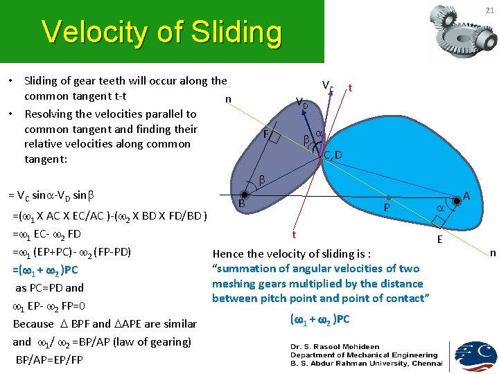
21 Velocity of Sliding • Sliding of gear teeth will occur along the common tangent t-t n • Resolving the velocities parallel to common tangent and finding their relative velocities along common tangent: VD F VC t C, D = VC sin -VD sin =( 1 X AC X EC/AC )-( 2 X BD X FD/BD ) = 1 EC- 2 FD = 1 (EP+PC)- 2 (FP-PD) =( 1 + 2 )PC as PC=PD and 1 EP- 2 FP=0 Because BPF and APE are similar and 1/ 2 =BP/AP (law of gearing) BP/AP=EP/FP B P t Hence the velocity of sliding is : “summation of angular velocities of two meshing gears multiplied by the distance between pitch point and point of contact” ( 1 + 2 )PC E A n
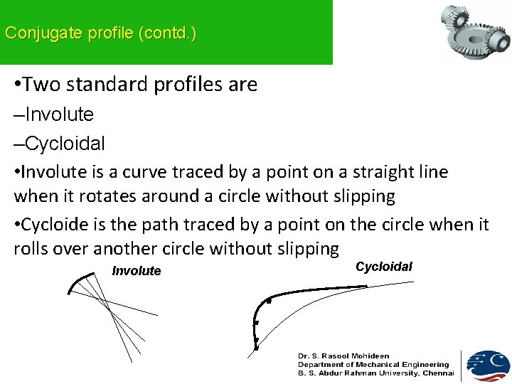
Conjugate profile (contd. ) • Two standard profiles are –Involute –Cycloidal • Involute is a curve traced by a point on a straight line when it rotates around a circle without slipping • Cycloide is the path traced by a point on the circle when it rolls over another circle without slipping Cycloidal Involute . .
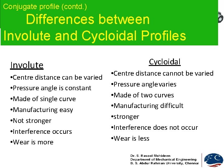
Conjugate profile (contd. ) Differences between Involute and Cycloidal Profiles Involute • Centre distance can be varied • Pressure angle is constant • Made of single curve • Manufacturing easy • Not stronger • Interference occurs • Wear is more Cycloidal • Centre distance cannot be varied • Pressure anglevaries • Made of two curves • Manufacturing difficult • stronger • Interference does not occur • Wear is less
Applications Agro Industry Automotive Gears Conveyor Systems Instrumentation Gears Marine Gears Mill heads Mining Gears Power Station Wind Turbine Dr. S. Rasool Mohideen Department of Mechanical Engg B. S. Abdur Rahman University, Chennai
Advantages • • • Transmits exact Velocity ratio Transmit larger power High efficiency Reliable Compact
Disadvantages • Manufacturing needs special tools • Errors in teeth lead to vibrations • Considerably expensive
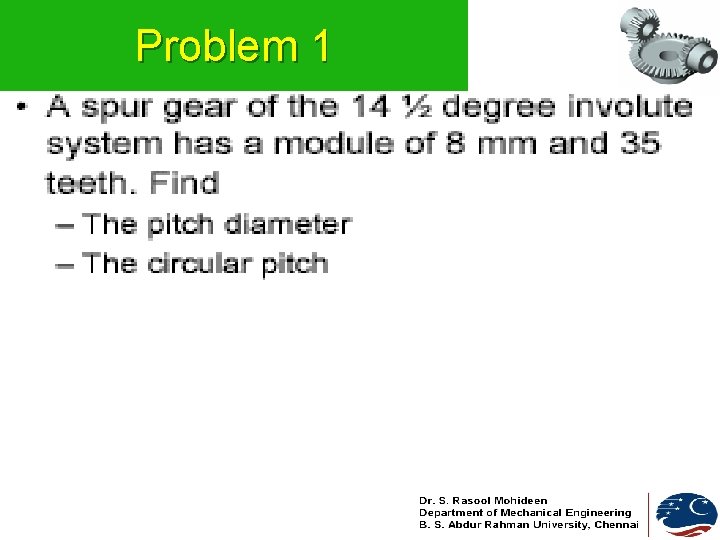
Problem 1
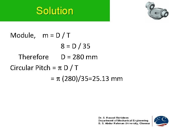
Solution Module, m = D / T 8 = D / 35 Therefore D = 280 mm Circular Pitch = D / T = (280)/35=25. 13 mm
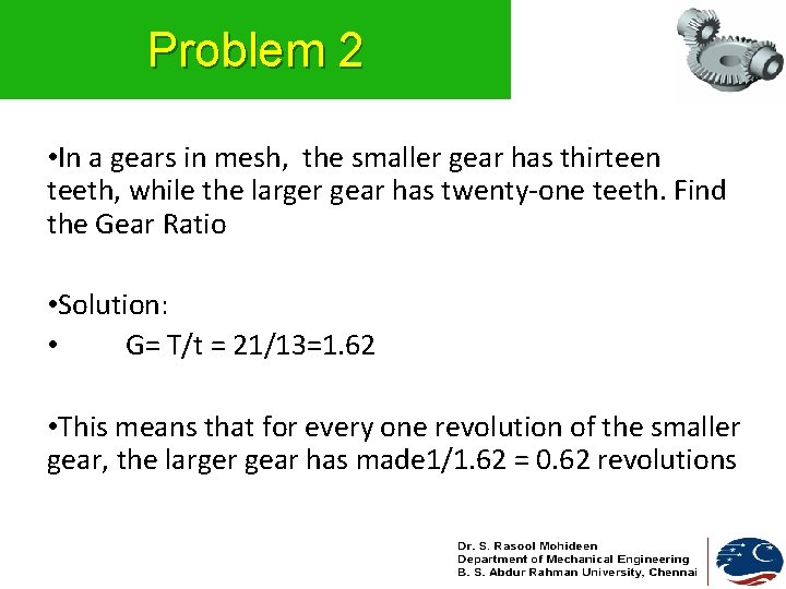
Problem 2 • In a gears in mesh, the smaller gear has thirteen teeth, while the larger gear has twenty-one teeth. Find the Gear Ratio • Solution: • G= T/t = 21/13=1. 62 • This means that for every one revolution of the smaller gear, the larger gear has made 1/1. 62 = 0. 62 revolutions