GEARS Gears Rugged Durable Can transmit power with

GEARS

Gears • • Rugged Durable Can transmit power with up to 98% efficiency Long service life

Motors • Motors convert electrical energy to mechanical energy. • Mechanical energy moves our robot • Motors drive the gears http: //www 2. towerhobbies. com/cgi-bin/wti 0001 p? &I=LR 9520&P=DS

Gears – Spur • Flat • Pinion – Bevel • Crown – Worm – Rack and Pinion – Differential www. mathworks. com

Gears • • Toothed wheels fixed to an axle. Drive gear – connected to the input axle. Driven gear – connected to the output axle. Gear train – when an number of gears are connected together. Gear Ratio = Number of driven teeth (output) Number of driver teeth (input)

Gear and Bearing Assemblies • Use as few views as possible – A full sectional view may be the only view necessary • Dimensions are normally omitted • Typically include balloons correlated with a parts list • May include torque data and lubricant information

Gear and Bearing Assemblies

Applications of Gears • • • Toys and Small Mechanisms – small, low load, low cost kinematic analysis Appliance gears – long life, low noise & cost, low to moderate load kinematic & some stress analysis Power transmission – long life, high load and speed kinematic & stress analysis Aerospace gears – light weight, moderate to high load kinematic & stress analysis Control gears – long life, low noise, precision gears kinematic & stress analysis

Spur Gears – Straight teeth mounted on parallel shafts – Many used at once to create very large gear reductions • Flat • Pinion http: //en. wikipedia. org/wiki/Gear#Worm_gear
 Spur gears – tooth profile is parallel to")
Types of Gears Gear (large gear) Spur gears – tooth profile is parallel to the axis of rotation, transmits motion between parallel shafts. Internal gears Pinion (small gear) Helical gears – teeth are inclined to the axis of rotation, the angle provides more gradual engagement of the teeth during meshing, transmits motion between parallel shafts. 10 Mechanical Engineering Dept. Ken Youssefi

Spur Gear Terminology • Teeth are straight and parallel to the gear shaft axis • Establish gear tooth profile using an involute curve • Basic rule: – No fewer than 13 teeth on the running gear and 26 teeth on the mating gear

Spur Gear Terminology • Pressure angle – 14. 5°and 20°are standard • Diametral pitch • Gear accuracy – Maximum tooth-to-tooth tolerances allowed, as specified by the American Gear Manufacturers Association (AGMA) • Several additional formulas and specifications

Bevel Gears – Gears that mesh at an angle, usually 90° – Changes the direction of rotation http: //science. howstuffworks. com/gear 4. htm

Bevel Gears • Shafts of the gear and pinion can intersect at 90°or any desired angle • Provide for a speed change between the gear and pinion, unless designed as miter gears

Types of Gears Bevel gears – teeth are formed on a Straight bevel gear conical surface, used to transfer motion between non-parallel and intersecting shafts. Spiral bevel gear 15 Mechanical Engineering Dept. Ken Youssefi

Crown Gears – Special form of bevel gear – Has right angles to the plane of the wheel http: //www. plastic-gear-manufacturer. com/industrial-gear. htm

Worm Gears – Changes the direction of turning motion by 90° – Decreases the speed of turning from screw to gear and increases the force http: //blogs. toolbarn. com/brianm/labels/Tool%20 Inner%20 Workings. html

Worm Gear Print

Worm Gears • Use a worm and worm gear • Large speed reduction in a small space • Worm locks in place when not in operation

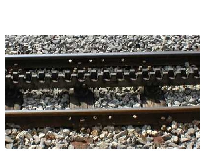
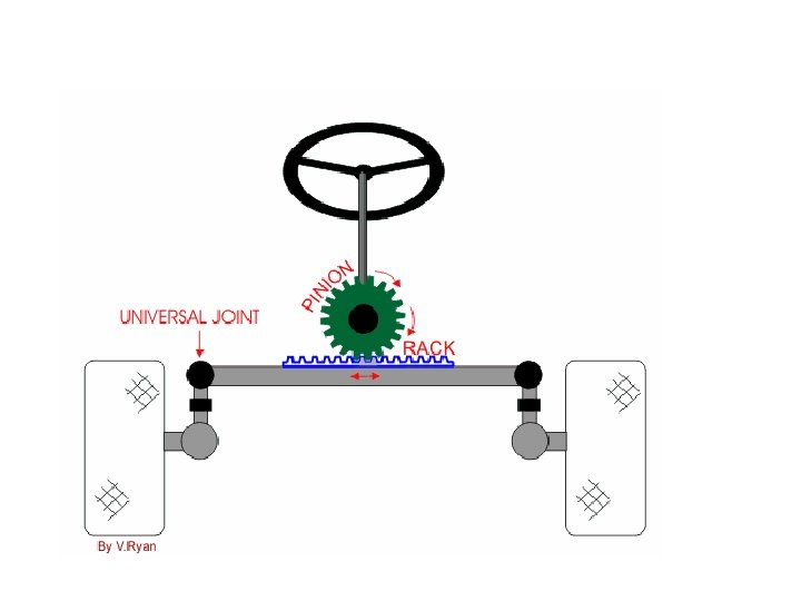
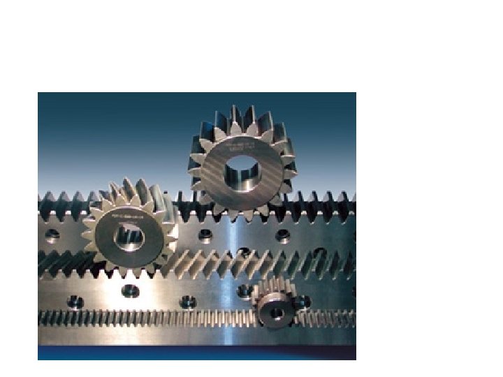
Rack and Pinion – Converts rotary motion to back and forth motion http: //en. wikipedia. org/wiki/Gear#Worm_gear

Rack and Pinion • Spur pinion operating on a flat straight bar rack • Converts rotary motion into straight-line motion

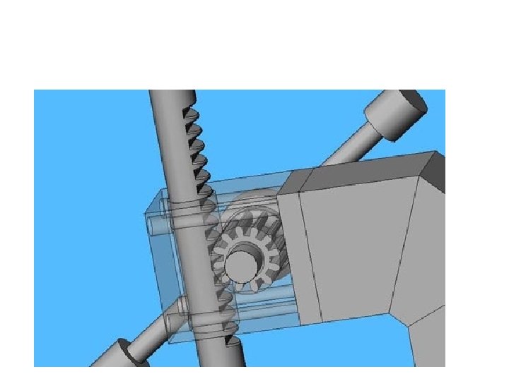
Differential Gears – Splits torque two ways, allowing each output to spin at a different speed http: //nxtasy. org/wp-content/uploads/2006/08/Differential 2 -00. html

Spur Gears • Transmit motion and power between parallel shafts • Two basic types: – External spur gears – Internal spur gears • Cluster gears

Spur Gears • Advantages: – Economical – Simple design – Ease of maintenance • Disadvantages: – Less load capacity – Higher noise levels

Helical Gears • Teeth cut at an angle – Allows more than one tooth to be in contact

Crossed Helical Gears • Also known as: – Right angle helical gears – Spiral gears • Low load-carrying capabilities

Helical Gears • Carry more load than equivalent-sized spur gears • Operate more quietly and smoothly • Develop end thrust – Can be eliminated using double helical gears, such as a herringbone gear

Gear Assemblies

Gear Assemblies – LEGO™ Technic 1031 Gear Assembly Activity – Gearing up and Gearing down http: //reprap. blogspot. com/2005_12_01_archiv

Cool Site • http: //nxtasy. org/ – Includes plans! • NXT Aerial Ropeway • NXT Gymnast • NXTWay-G: Balancing with a Gyro Sensor February 19, 2007 Created by Dr. T. E. Varnado

GEARS-Wheel and Axel • Each gear in a series reverses the direction of rotation of the previous gear. The smaller gear will always turn faster than the larger gear.

Common Gear Materials • • • Cast iron Steel Brass Bronze alloys Plastic

Gear Selection and Design • Often done through vendors’ catalogs or the use of standard formulas – American Gear Manufacturers Association (AGMA) • AGMA 2000 -A 88, Gear Classification and Inspection Handbook - Tolerances and Measuring Methods for Unassembled Spur and Helical Gears, including Metric Equivalents – American Society of Mechanical Engineers (ASME) • ASME Y 14. 7. 1 Gear Drawing Standards - Part 1: For Spur, Helical, Double Helical and Rack • ASME Y 14. 7. 2 Gear and Spline Drawing Standards - Part 2: Bevel and Hypoid Gears

Gear Train • Increase or reduce speed • Change the direction of motion from one shaft to another

Gear Structure

Splines • Often used when it is necessary for the gear or pulley to easily slide on the shaft • Can also be nonsliding • Stronger than keyways and keys

Intersecting Shafting Gears • Bevel gears • Face gears

Face Gears • Combination of bevel gear and spur pinion, or bevel gear and helical pinion • Requires less mounting accuracy • Caries less load

Nonintersecting Shafting Gears • Crossed helical gears • Hypoid gears • Worm gears

Hypoid Gears • Offset, nonintersecting gear shaft axes • Very smooth, strong, and quiet

Hypoid Gear Representations

Simplified Gear Representation

Detailed Spur Gear Representation

Showing a Gear Tooth Related to Another Feature

Cluster Gear Print

Gear Trains • Transmit motion between shafts • Decrease or increase the speed between shafts • Change the direction of motion

Gear Ratio • Important when designing gear trains • Applies to any two gears in mesh • Expressed as a proportion, such as 2: 1 or 4: 1

Rack and Pinion Print

Bevel Gear Print

Plastic Gears • Generally designed in the same manner as gears made from other materials • Glass fiber adds reinforcement and reduces thermal expansion • Additives that act as built-in lubricants and provide increased wear resistance: – Polytetrafluoroethylene (PTFE) – Silicones – Molybdenum disulphide

Advantages of Molded Plastic Gears • • Reduced cost Increased efficiency Self-lubrication Increased tooth strength with nonstandard pressure angles Reduced weight Corrosion resistance Less noise Available in colors

Disadvantages of Molded Plastic Gears • • Lower strength Greater thermal expansion and contraction Limited heat resistance Size change with moisture absorption

Planetary Gear Trains - Example For the speed reducer shown, the input shaft a is in line with output shaft b. The tooth numbers are N 2=24, N 3=18, N 5=22, and N 6=64. Find the ratio of the output speed to the input speed. Will both shafts rotate in the same direction? Gear 6 is a fixed internal gear. Train value = (-N 2 / N 3)(N 5 / N 6) = (-24/18)(22/64) = -. 4583 = (ωL – ωarm) / (ωF – ωarm) = (0 – ωarm) / (1 – ωarm) ωarm =. 125, reduction is 8 to 1 Input and output shafts rotate in d 2 + d 3 = d 6 – d 5 the same direction 57 Mechanical Engineering Dept. Ken Youssefi

Harmonic Drive The mechanism is comprised of three components: Wave Generator, Flexspline, and Circular Spline. Wave Generator Consists of a steel disk and a specially design bearing. The outer surface has an elliptical shape. The ball bearing conforms to the same elliptical shape of the wave generator. The wave generator is usually the input. Flexspline The Flexspline is a thin-walled steel cup with gear teeth on the outer surface near the open end of the cup. Flexspline is usually the output. Circular Spline Rigid internal circular gear, meshes with the external teeth on the Flexspline. 58 Mechanical Engineering Dept. Ken Youssefi

Harmonic Drive Teeth on the Flexspline and circular spline simultaneously mesh at two locations which are 180 o apart. As the wave generator travels 180 o, the flexspline shifts one tooth with respect to circular spline in the opposite direction. The flexspline has two less teeth than the circular spline. Gear Ratio ωWave Generator 59 = input, = - (Nflex spline)/ 2 ω Flexspline = output, ω Circular Spline Mechanical Engineering Dept. =0 Ken Youssefi

Bearings

Bearings • Two large groups: – Plain bearings – Rolling element bearings • Accommodate either rotational or linear motion

Plain Bearings • Often referred to as: – Sleeve bearings – Journal bearings – Bushings • Operation is based on a sliding action between mating parts • Clearance fit between the inside diameter of the bearing and the shaft is critical

Plain Bearings

Rolling Element Bearings • Common classes: – Ball bearings – Roller bearings

Ball Bearings • Typically have higher speed and lower load capabilities than roller bearings • May have a shield or seal

Typical Ball Bearings • • Single-row ball bearings Double-row ball bearings Angular contact ball bearings Thrust bearings

Roller Bearings • More effective than ball bearings for heavy loads

Bearing Codes • Typically specify: – Material – Bearing type – Bore size – Lubricant – Type of seals or shields

Bearing Selection • A variety of bearing types are available depending on use requirements • Common classes: – Light bearings – Medium bearings – Heavy bearings

Bearing Bore, Outside Diameters, and Width

Shaft and Housing Fits • Important consideration – Tight fits can cause failure of the balls, rollers, lubricant, or overheating – Loose fits can cause slippage of the bearing in the housing, resulting in overheating, vibration, or excessive wear

Shaft and Housing Fits • General shaft fits – Shaft diameter and tolerance are the same as the bearing bore diameter and tolerance • General housing fits – Minimum housing diameter is. 0001 larger than the maximum bearing outside diameter – Maximum housing diameter is. 0003 larger than the minimum housing diameter

The Shaft Shoulder and Housing Shoulder Dimensions • Shoulders should be large enough to rest flat on the face of the bearing and small enough to allow bearing removal
 in")
Surface Finish of Shaft and Housing • Shafts under 2 inches (50 mm) in diameter: – 32 microinches (0. 80 micrometer) • Shafts over 2 inches in diameter – 63 microinch (1. 6 micrometer) • Housing diameter: – 125 microinch (3. 2 micrometer)

Bearing Lubrication • Necessary requirement based on: – Type of operation, such as continuous or intermittent – Service speed in rpm (revolutions per minute) – Bearing load, such as light, medium, or heavy

Oil Grooving of Bearings • Grooves for the proper flow of lubrication to the bearing surface – Help provide the proper lubricant between the bearing surfaces and maintain cooling • Several methods available

Sealing Methods • • • Static sealing Dynamic seals Gaskets Molded lip packings Molded ring seals – Labyrinth – O-ring seal – Lobed ring seal • Felt seals and wool seals

Bearing Mountings
- Slides: 78