GEAR DESIGN Part II Lec 9 Dr Ameer


 Output Power (Torque")


 It is a measure of the size of the gear and")


- Slides: 20
GEAR DESIGN Part II Lec. 9 Dr. Ameer Ali Kamel Prod. Eng. & Mech. Design Dept. Faculty of Engineering
1. INTRODUCTION A. Gear shape Spur Gear ﺗﺮﺱ ﻋﺪﻝ Helical Gear ﺗﺮﺱ ﻣﺎﺋﻞ
Single-face Gear Double-face Gear
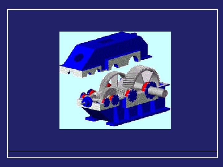
B. Gear Boxes Fixed speed Gear box Variable speed Gear box
Single and Double Stage Gear Box Single Stage Gear Box NA Input Power (Torque & Speed) Output Power (Torque & Speed) NB
Double Stage Gear Box NA NB Input Power (Torque & Speed) Output Power (Torque & Speed)
1. TERMINOLOGY OF GEARS Gears are considered as mechanical elements, by which the contact surfaces are provided with grooves that prevent slip and ensure positive means of transmitting rotation. Gears are used as speed converters when a constant speed ratio between two axes with high accuracy is required. However, gears are used if the center distance between the shafts is relative small. But, it is important to notice that, gears required special equipment for manufacturing and no machining error is allowable by gear cutting.
SPUR GEAR DEFINITIONS By gear meshing, the larger one is called “gear” and the smaller is called “pinion”. The pinion can be the driver if the gear meshing is “reduction unit” while the gear should be the driver in the case of “increasing speed unit”. The “pitch circle” measurement. is the basis of gear The size of the gear is the pitch circle diameter. The “addendum circle” is the circle, which bounds the outer ends of the teeth.
The addendum “a” is the radial distance between the pitch circle and the addendum circle. i. e. D a = Dp + 2 a The “dedendum circle” bounds the bottom of the teeth. The dedendum “d” is the radial distance between pitch circle and the dedendum circle. i. e. D d = Dp – 2 d The tooth height “h” is the summation of the adedendum and dedendum. i. e. h = a + d The clearance “c” is a safety distance between the gear addendum and the pinion dedendum.
The clearance “c” is a safety distance between the gear addendum and the pinion dedendum. The tooth space is the width of the empty space on the pitch circle. The tooth thickness is the width of the material space on the pitch circle. i. e. Tooth thickness < Tooth space The “bachlach” is the difference between the tooth space and the tooth thickness. i. e. Backlach = tooth space – tooth thickness.
Circular Pitch (Pc) It is a measure of the size of the gear and defined as the distance from a point on one tooth to the corresponding point on an adjacent tooth measured on the pitch circle. where, “D” is the pitch diameter and “Z” is the number of teeth. Module (m) It is the pitch circle diameter in millimeter divided by the number of teeth.
Therefore, the circular pitch “Pc” is connected with the module "m" with the following relation: The tooth Face It is the surface of the tooth between the pitch cylinder and the addendum cylinder. The tooth Flank It is the distance between the pitch cylinder and the root cylinder.
PROPERTIES OF STANDARD GEAR TEETH 14. 50 Composite 0 14. 50 Full depth involute 200 Stub Involute Addedendu m (a) m m m 0. 8 m Dededendu m (d) 1. 157 m m Whole depth (h) 2. 157 m 1. 8 m 0. 157 m Clearance (C ) 0. 157 m 0. 2 m
STANDARD MODULES Prferred Second choice 1 1. 25 2 2. 5 3 4 5 6 10 12 16 20 25 32 40 50 1. 125 1. 375 1. 75 2. 25 2. 75 3. 5 4. 5 5. 5 9 11 14 18 22 28 36 45 8 7
The base circle It is an auxiliary circle used in involute gearing to generate the tooth profile. ANGULAR VELOCITY RATIO “K” It is the ratio of the angular velocity of the pinion to the angular velocity of its mating gear (wheel). It is inversely proportional to the number of teeth on the two gears, and it is also (by spur gear) inversely proportional to the pitch diameters.
Meshed Gears dum n e dd cle r i C A h c Pit se a B c Circular pitch Tooth Space le le rc Ci Deddendum Circle Toot h Thic knes s a h d h’ C The point “O” is called the “pitch point”. Line of action It is a line normal to a pair of mating tooth profiles at their point of contact.
Gear Meshing dum n e dd cle r i C A Pit ch se a B c Cir Tooth Space le cle r Ci Circular pitch Deddendum Circle Toot h Thic knes s a h d h’ C Pressure angle ( ) It is the angle between the line of action and the common tangent to the pitch circle at the pitch point.
INTERFERANCE OF TEETH Under certain conditions, involute profiles overlap or cut into the mating teeth or the clearance between the bottom of the teeth and the topface of the other mating teeth is vanished. This phenomenon is called ‘interference’ which can be avoided if the maximum addedendum radius for each gear is equal to or less than the following value:
EN D