FUTURE IRRADIATION FACILITIES AT CERN Lucie Linssen PHLCD
- Slides: 32
FUTURE IRRADIATION FACILITIES AT CERN Lucie Linssen PH/LCD - for the Irradiation Facilities WG http: //cern. ch/irradiation-facilities Outline Introduction on irradiation facilities Present situation User survey � Future prospects � Possible implementations CERN, May 13 th 2009 Summary Lucie Linssen, Physics Opportunities Workshop 1
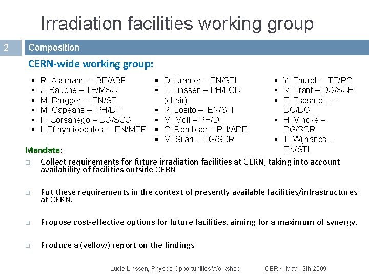
Irradiation facilities working group 2 Composition CERN-wide working group: § § § R. Assmann – BE/ABP J. Bauche – TE/MSC M. Brugger – EN/STI M. Capeans – PH/DT F. Corsanego – DG/SCG I. Efthymiopoulos – EN/MEF § D. Kramer – EN/STI § L. Linssen – PH/LCD (chair) § R. Losito – EN/STI § M. Moll – PH/DT § C. Rembser – PH/ADE § M. Silari – DG/SCR § Y. Thurel – TE/PO § R. Trant – DG/SCH § E. Tsesmelis – DG/DG § H. Vincke – DG/SCR § T. Wijnands – EN/STI Mandate: Mandate Collect requirements for future irradiation facilities at CERN, taking into account availability of facilities outside CERN Put these requirements in the context of presently available facilities/infrastructures at CERN. Propose cost-effective options for future facilities, aiming for a maximum of synergy. Produce a (yellow) report on the findings Lucie Linssen, Physics Opportunities Workshop CERN, May 13 th 2009
Introduction 3 q q Irradiation facilities – what for? Setup and operate an irradiation facility – what it really involves? Lucie Linssen, Physics Opportunities Workshop CERN, May 13 th 2009
Irradiation facilities 4 What for? Test and development of prototypes or final assemblies before installation in a radiation environment � issues addressed (not exhaustive) SEU, radiation damage, performance degradation of electronics beam impact or radiation damage on materials performance degradation after long exposure (ageing) performance evaluation under background/”noise” conditions � passive or “hot” (i. e. online) irradiations Test or calibration of components � radiation measurement/monitoring devices � feedback data to simulation codes Lucie Linssen, Physics Opportunities Workshop CERN, May 13 th 2009
Setup and operate an irradiation facility 5 What it really involves? Deliver the desired beam � � � intensity, beam spot, time structure (slow or fast extraction) steering : beam and/or equipment (scanning table) monitoring of beam intensity and radiation field Know and control the radiation environment � � provide detailed Monte Carlo simulations in order to have well-defined spectra in-situ dosimetry providing information on the actual doses accumulated escaping radiation (by shielding) and internal activation (by design) must remain within limits for high intensities: reference maps available to users closed ventilation loop, humidity control Impact on infrastructure – optimized maintenance procedures Access conditions � � � pre-test documentation, preparation and optimization: materials, time access authorization, training traceability : in/out movements, logs, RP control Lucie Linssen, Physics Opportunities Workshop CERN, May 13 th 2009
Setup and operate an irradiation facility 6 … what it really involves? Auxiliary installations � � � nearby control room for “hot” tests during exposure remote handling of equipment and services storage area � qualified lab to work on exposed materials � modify for re-use, analysis after irradiation flexible detector infrastructure initial cool down just after exposure medium/long term storage in view of future re-use E. g. gas systems, cooling Final product: make scientific results available to the community � document and spread out the knowledge results database: materials, components, . . and radioactive waste must be considered from the beginning ! Lucie Linssen, Physics Opportunities Workshop CERN, May 13 th 2009
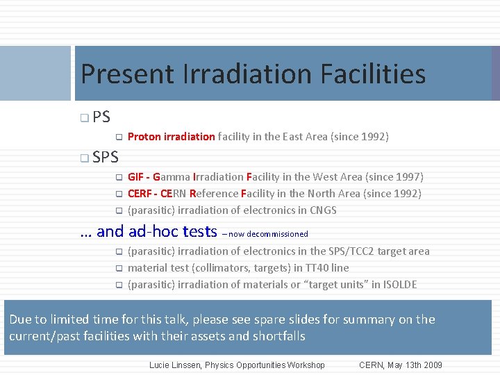
Present Irradiation Facilities 7 q PS q q Proton irradiation facility in the East Area (since 1992) SPS q q q GIF - Gamma Irradiation Facility in the West Area (since 1997) CERF - CERN Reference Facility in the North Area (since 1992) (parasitic) irradiation of electronics in CNGS … and ad-hoc tests – now decommissioned q q q (parasitic) irradiation of electronics in the SPS/TCC 2 target area material test (collimators, targets) in TT 40 line (parasitic) irradiation of materials or “target units” in ISOLDE Due to limited time for this talk, please see spare slides for summary on the current/past facilities with their assets and shortfalls Lucie Linssen, Physics Opportunities Workshop CERN, May 13 th 2009
User survey 8 q Survey results q Requirements, future prospects, q Possible implementations Lucie Linssen, Physics Opportunities Workshop CERN, May 13 th 2009
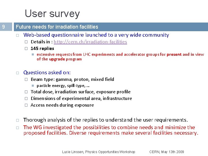
User survey 9 Future needs for irradiation facilities Web-based questionnaire launched to a very wide community � � Details in : http: //cern. ch/irradiation-facilities 145 replies Questions asked on: � Beam type: gamma, proton, mixed field � � � extensive requests from LHC experiments and accelerator groups for present and in view of the upgrade program particle energy, spill-type, … Total dose, irradiation surface, exposure profile Dimensions of experimental area, infrastructure Access needs during exposure Thorough analysis of the replies to understand the user requirements. The WG investigated the possibilities to combine needs and minimize the proposed facilities. Diverse requirements make several facilities necessary. Lucie Linssen, Physics Opportunities Workshop CERN, May 13 th 2009
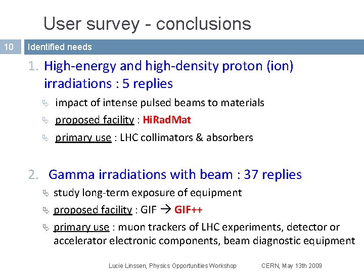
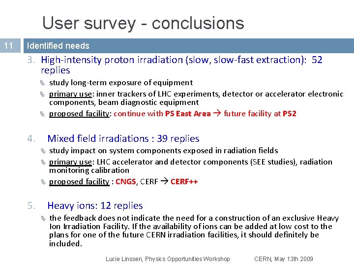
User survey - conclusions 10 Identified needs 1. High-energy and high-density proton (ion) irradiations : 5 replies Ä impact of intense pulsed beams to materials Ä proposed facility : Hi. Rad. Mat Ä primary use : LHC collimators & absorbers 2. Gamma irradiations with beam : 37 replies study long-term exposure of equipment Ä proposed facility : GIF++ Ä primary use : muon trackers of LHC experiments, detector or accelerator electronic components, beam diagnostic equipment Ä Lucie Linssen, Physics Opportunities Workshop CERN, May 13 th 2009
User survey - conclusions 11 Identified needs 3. High-intensity proton irradiation (slow, slow-fast extraction): 52 replies Ä Ä Ä 4. study long-term exposure of equipment primary use: inner trackers of LHC experiments, detector or accelerator electronic components, beam diagnostic equipment proposed facility: continue with PS East Area future facility at PS 2 Mixed field irradiations : 39 replies Ä Ä Ä 5. study impact on system components exposed in radiation fields primary use: LHC accelerator and detector components (SEE studies), radiation monitoring calibration proposed facility : CNGS, CERF++ Heavy ions: 12 replies Ä the feedback does not indicate the need for a construction of an exclusive Heavy Ion Irradiation Facility. If the availability of ions can be added at low cost to the plans for one of the future CERN irradiation facilities, it should definitely be included. Lucie Linssen, Physics Opportunities Workshop CERN, May 13 th 2009
The Hi. Rad. Mat Facility 12 Key assets Study the impact of intense pulsed beams on materials � Thermal management (heating) material damage even below melting point material vaporization (extreme conditions) � Radiation damage to materials – change of properties � Thermal shock - beam induced pressure waves Test bed, important for the design validation of LHC nearbeam components before installation in the machine Requires LHC-type beam from pilot to 288 nominal bunches Lucie Linssen, Physics Opportunities Workshop CERN, May 13 th 2009
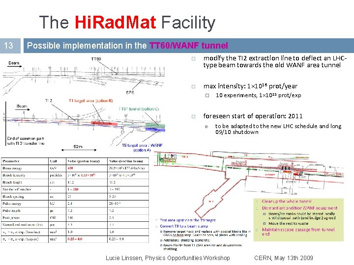
The Hi. Rad. Mat Facility 13 Possible implementation in the TT 60/WANF tunnel modify the TI 2 extraction line to deflect an LHCtype beam towards the old WANF area tunnel max intensity: 1× 10¹⁶ prot/year � 10 experiments, 1× 10 15 prot/exp foreseen start of operation: 2011 to be adapted to the new LHC schedule and long 09/10 shutdown Lucie Linssen, Physics Opportunities Workshop CERN, May 13 th 2009
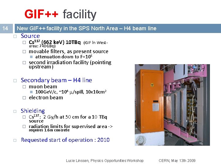
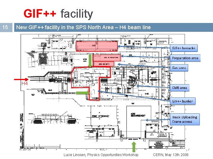
GIF++ facility 14 New GIF++ facility in the SPS North Area – H 4 beam line Source � Cs 137 (662 ke. V) 10 TBq � movable filters, as present source area: 740 GBq) � second irradiation facility (pointing upstream) muon beam � 100 Ge. V/c, ~104 m/spill, 10 x 10 cm 2 electron beam Shielding � � attenuation down to F=105 Secondary beam – H 4 line � (GIF in West- Cs 137: 2 Gy/h at 50 cm for a 10 TBq source radiation limits for supervised area -> requires 1. 6 m concrete Requested start of operation : 2010 Lucie Linssen, Physics Opportunities Workshop CERN, May 13 th 2009
GIF++ facility 15 New GIF++ facility in the SPS North Area – H 4 beam line H 4 Lucie Linssen, Physics Opportunities Workshop CERN, May 13 th 2009
Proton irradiation 16 Proposal Maintain with minimal investment the PS East Area facility improved duty time to gain x 2 in integrated rate (scheduling? ) � upgrade in the beam monitoring systems � upgrade in the mobile trolley and cabling � Plan for a high-intensity proton irradiation facility coupled to the future PS 2 � � PS 2 facility at 20 Ge. V is preferred 20 Ge. V is already conveniently used at the PS allows placing several samples in the beam at the same time Flux: 1. 1 1012 protons/pulse (16. 8 s interval) Fluence: 2 x 10¹⁶ p/cm 2 over ~5 cm 2 to be reached in two weeks Future PS 2 proton and mixed field irradiations could co-exist Lucie Linssen, Physics Opportunities Workshop CERN, May 13 th 2009
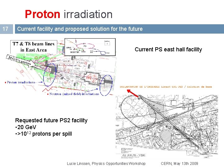
Proton irradiation 17 Current facility and proposed solution for the future Current PS east hall facility Requested future PS 2 facility • 20 Ge. V • >1012 protons per spill Lucie Linssen, Physics Opportunities Workshop CERN, May 13 th 2009
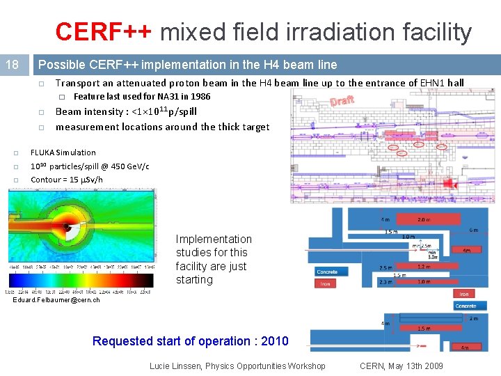
CERF++ mixed field irradiation facility 18 Possible CERF++ implementation in the H 4 beam line Transport an attenuated proton beam in the H 4 beam line up to the entrance of EHN 1 hall � Feature last used for NA 31 in 1986 Beam intensity : <1× 10¹¹ p/spill measurement locations around the thick target FLUKA Simulation 1010 particles/spill @ 450 Ge. V/c Contour = 15 m. Sv/h Implementation studies for this facility are just starting Eduard. Felbaumer@cern. ch Requested start of operation : 2010 Lucie Linssen, Physics Opportunities Workshop CERN, May 13 th 2009
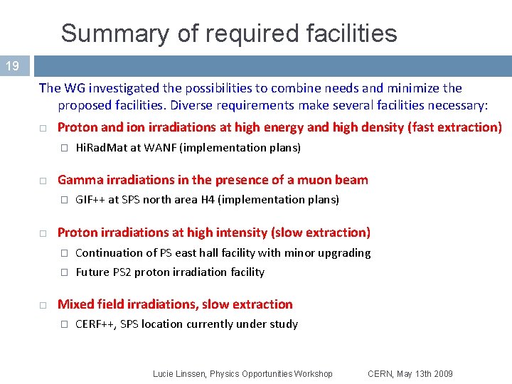
Summary of required facilities 19 The WG investigated the possibilities to combine needs and minimize the proposed facilities. Diverse requirements make several facilities necessary: Proton and ion irradiations at high energy and high density (fast extraction) � Gamma irradiations in the presence of a muon beam � Hi. Rad. Mat at WANF (implementation plans) GIF++ at SPS north area H 4 (implementation plans) Proton irradiations at high intensity (slow extraction) � Continuation of PS east hall facility with minor upgrading � Future PS 2 proton irradiation facility Mixed field irradiations, slow extraction � CERF++, SPS location currently under study Lucie Linssen, Physics Opportunities Workshop CERN, May 13 th 2009
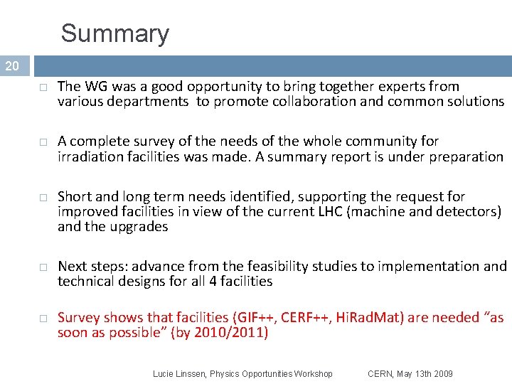
Summary 20 The WG was a good opportunity to bring together experts from various departments to promote collaboration and common solutions A complete survey of the needs of the whole community for irradiation facilities was made. A summary report is under preparation Short and long term needs identified, supporting the request for improved facilities in view of the current LHC (machine and detectors) and the upgrades Next steps: advance from the feasibility studies to implementation and technical designs for all 4 facilities Survey shows that facilities (GIF++, CERF++, Hi. Rad. Mat) are needed “as soon as possible” (by 2010/2011) Lucie Linssen, Physics Opportunities Workshop CERN, May 13 th 2009
Spare slides 21 Lucie Linssen, Physics Opportunities Workshop CERN, May 13 th 2009
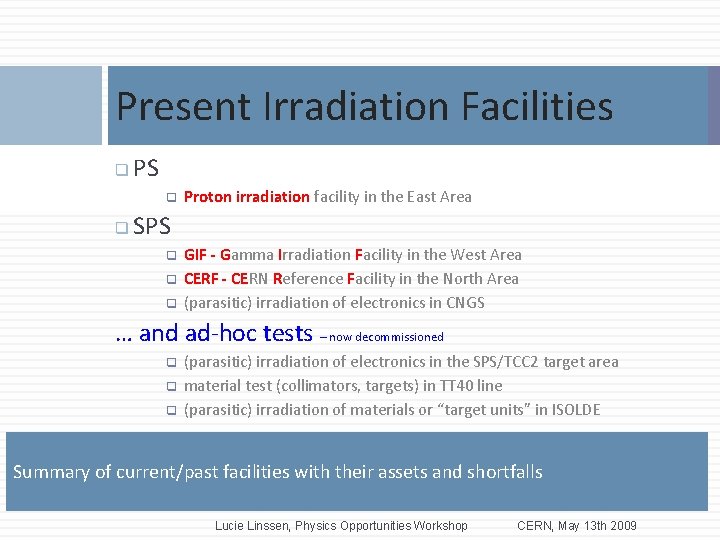
Present Irradiation Facilities 22 q PS q q Proton irradiation facility in the East Area SPS q q q GIF - Gamma Irradiation Facility in the West Area CERF - CERN Reference Facility in the North Area (parasitic) irradiation of electronics in CNGS … and ad-hoc tests – now decommissioned q q q (parasitic) irradiation of electronics in the SPS/TCC 2 target area material test (collimators, targets) in TT 40 line (parasitic) irradiation of materials or “target units” in ISOLDE Summary of current/past facilities with their assets and shortfalls Lucie Linssen, Physics Opportunities Workshop CERN, May 13 th 2009
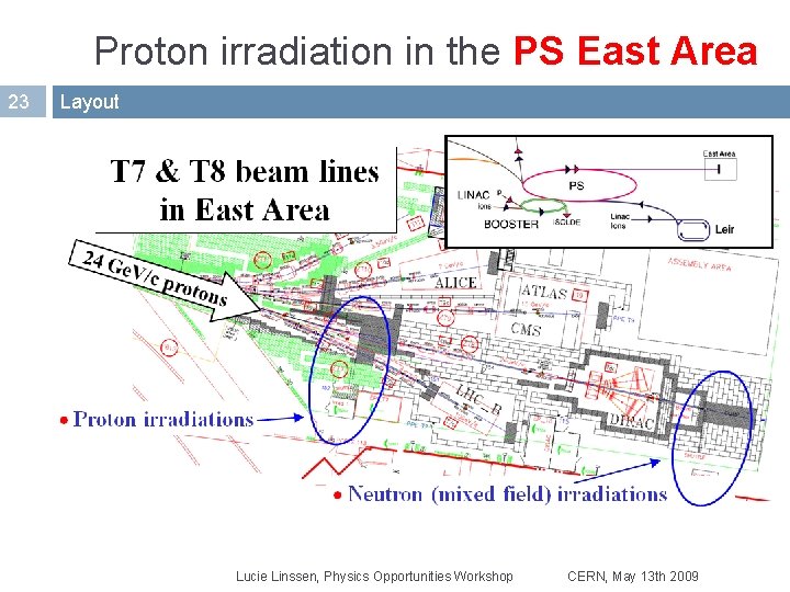
Proton irradiation in the PS East Area 23 Layout Lucie Linssen, Physics Opportunities Workshop CERN, May 13 th 2009
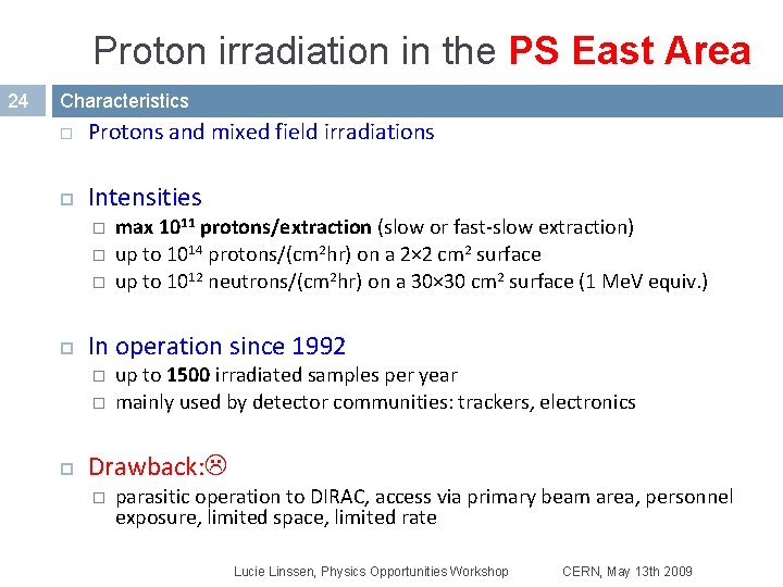
Proton irradiation in the PS East Area 24 Characteristics Protons and mixed field irradiations Intensities � � � In operation since 1992 � � max 1011 protons/extraction (slow or fast-slow extraction) up to 1014 protons/(cm 2 hr) on a 2× 2 cm 2 surface up to 1012 neutrons/(cm 2 hr) on a 30× 30 cm 2 surface (1 Me. V equiv. ) up to 1500 irradiated samples per year mainly used by detector communities: trackers, electronics Drawback: � parasitic operation to DIRAC, access via primary beam area, personnel exposure, limited space, limited rate Lucie Linssen, Physics Opportunities Workshop CERN, May 13 th 2009
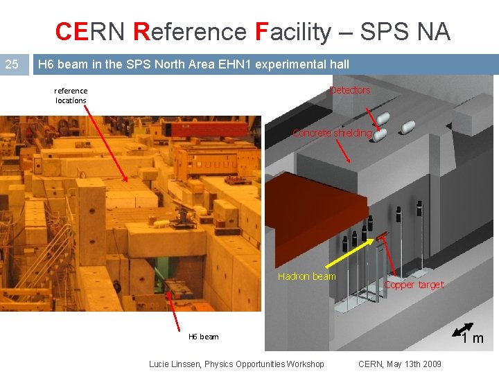
CERN Reference Facility – SPS NA 25 H 6 beam in the SPS North Area EHN 1 experimental hall Detectors reference locations Concrete shielding Hadron beam Copper target 1 m H 6 beam Lucie Linssen, Physics Opportunities Workshop CERN, May 13 th 2009
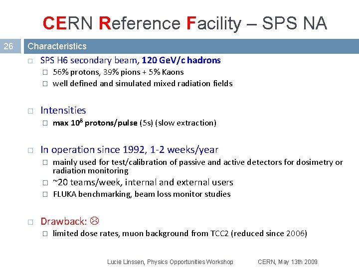
CERN Reference Facility – SPS NA 26 Characteristics SPS H 6 secondary beam, 120 Ge. V/c hadrons � � Intensities � max 108 protons/pulse (5 s) (slow extraction) In operation since 1992, 1 -2 weeks/year � 56% protons, 39% pions + 5% Kaons well defined and simulated mixed radiation fields mainly used for test/calibration of passive and active detectors for dosimetry or radiation monitoring � ~20 teams/week, internal and external users � FLUKA benchmarking, beam loss monitor studies Drawback: � limited dose rates, muon background from TCC 2 (reduced since 2006) Lucie Linssen, Physics Opportunities Workshop CERN, May 13 th 2009
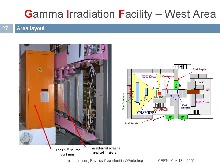
Gamma Irradiation Facility – West Area 27 Area layout The Cs 137 source container The external screens and collimators Lucie Linssen, Physics Opportunities Workshop CERN, May 13 th 2009
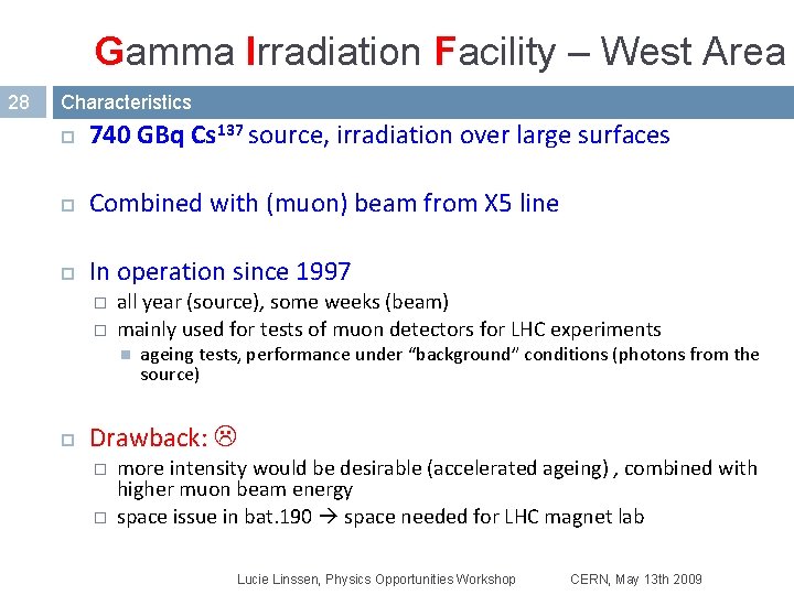
Gamma Irradiation Facility – West Area 28 Characteristics 740 GBq Cs 137 source, irradiation over large surfaces Combined with (muon) beam from X 5 line In operation since 1997 � � all year (source), some weeks (beam) mainly used for tests of muon detectors for LHC experiments ageing tests, performance under “background” conditions (photons from the source) Drawback: � � more intensity would be desirable (accelerated ageing) , combined with higher muon beam energy space issue in bat. 190 space needed for LHC magnet lab Lucie Linssen, Physics Opportunities Workshop CERN, May 13 th 2009
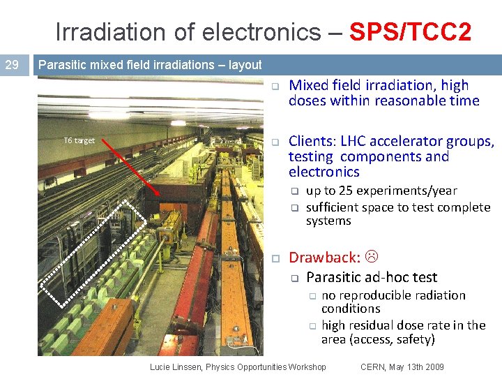
Irradiation of electronics – SPS/TCC 2 29 Parasitic mixed field irradiations – layout q T 6 target q Mixed field irradiation, high doses within reasonable time Clients: LHC accelerator groups, testing components and electronics q q up to 25 experiments/year sufficient space to test complete systems Drawback: q Parasitic ad-hoc test q q no reproducible radiation conditions high residual dose rate in the area (access, safety) Lucie Linssen, Physics Opportunities Workshop CERN, May 13 th 2009
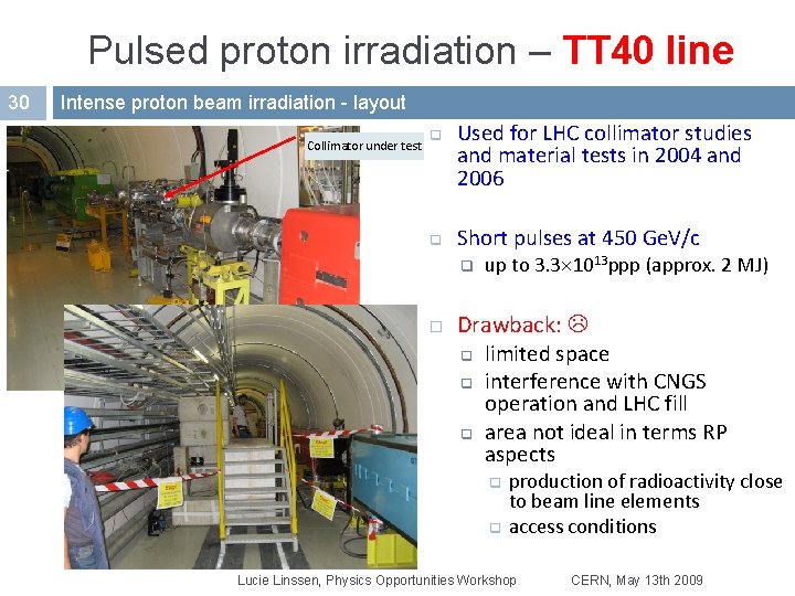
Pulsed proton irradiation – TT 40 line 30 Intense proton beam irradiation - layout Collimator under test q q Used for LHC collimator studies and material tests in 2004 and 2006 Short pulses at 450 Ge. V/c q up to 3. 3 1013 ppp (approx. 2 MJ) Drawback: q limited space q interference with CNGS operation and LHC fill q area not ideal in terms RP aspects q q production of radioactivity close to beam line elements access conditions Lucie Linssen, Physics Opportunities Workshop CERN, May 13 th 2009
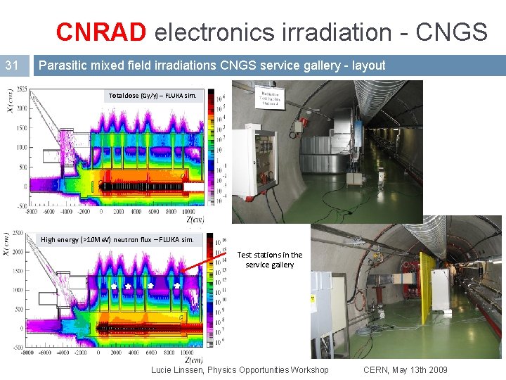
CNRAD electronics irradiation - CNGS 31 Parasitic mixed field irradiations CNGS service gallery - layout Total dose (Gy/y) – FLUKA sim. High energy (>10 Me. V) neutron flux – FLUKA sim. Test stations in the service gallery Lucie Linssen, Physics Opportunities Workshop CERN, May 13 th 2009
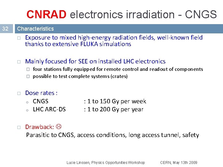
CNRAD electronics irradiation - CNGS 32 Characteristics Exposure to mixed high-energy radiation fields, well-known field thanks to extensive FLUKA simulations Mainly focused for SEE on installed LHC electronics � � four stations fully equipped for remote control and readout of components possible to test complete systems (crates) Dose rates : o CNGS o LHC ARC-DS : 1 to 150 Gy per week : 1 to 200 Gy per year Drawback: Parasitic to CNGS, access conditions, long access tunnel, safety Lucie Linssen, Physics Opportunities Workshop CERN, May 13 th 2009