Flexure Mounts For High Resolution Optical Elements Mir


 Inward CT The Lens 120º")


- Slides: 28
Flexure Mounts For High Resolution Optical Elements Mir Salek Optomechanics Fall 2008 Review of: Vukobratovich D, Richard R M, Proc of SPIE Vol. 0959, Jan 1988
Summary n n What is a flexure? Compare to other mounts Basic types of Flexure Some examples
What is a Flexure By definition, flexure is an elastic element which provides controlled motion n
Plunging to the Idea Lens Mount
Plunging to the Idea CR (idea from Yoder’s book) Inward CT The Lens 120º CT 120º CR CR CT
Points n n n Equal Compliances -> Keeps the lens centered when temperature changes The spring forces allow the lens to decenter during shocks and return afterwards Minimize stress in optics during shocks Typically stiff tangentionally and axially and compliant radially Uses Kinematic principles to find the location of flexures
High Performance Lens Assembly n n Tight tolerance alignment Maintain alignment under operational level shock, vibration, pressure, temperature change Retain its alignment upon exposure to survival level of environmental effects Low stress on optics (particularly mirrors)
Advantages of Flexure Mounts n Free of slick-slip and friction effects of semikinematic design Less hysteresis than rolling or sliding contacts More robust to adverse environment effects such as extreme temperatures, vacuum, and abrasive dust Needs very little maintenance if any * Ideal for space applications n n n
Flexure Material n n Should provide required compliance within length limitation Should have high dimensional stability for repeated use in time
Flexure Material n n Should have high fracture toughness Thermal properties to maintain operation with temperature change
Compliance n n For a given length: Higher RTS ->maximum compliance Reduced tensile strength is the ratio of yield strength to modulus of elasticity.
Dimensional Stability n n Material instability or room temperature creep can happen at stresses less than micro-yield strength Andrea’s Beta Law predicts instability with time: ε = βtm m ≈ 0. 33
Flexure Design
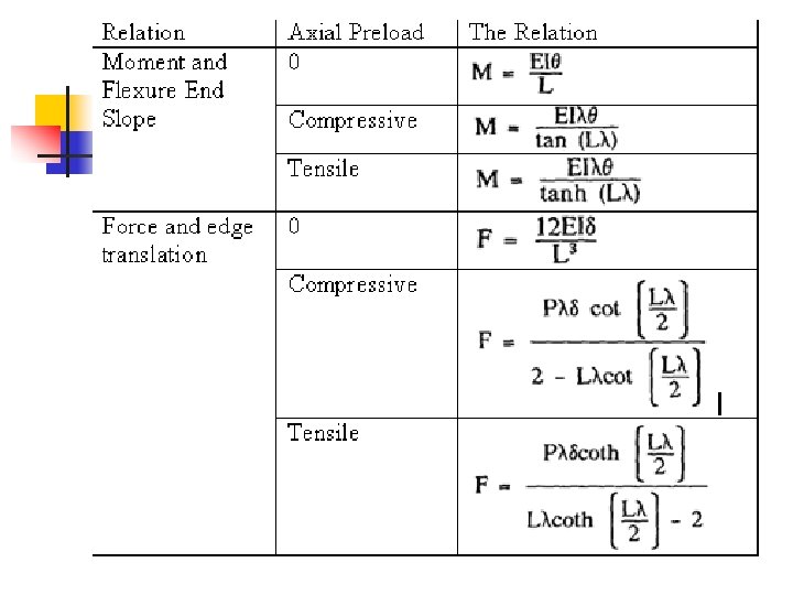
Basic Flexures: Single Strip Flexure n n It can be used to guide both translation and rotation The strain is a function of axial preload
In the table n n n n n L is the flexure length; E is the elastic modulus; I is the moment of inertia; P is the applied axial load; θ is the end slope of the flexure; M is the applied torque; δ is the end displacement of the flexure; F is the applied force; .
Strain versus Axial Stress constant force
Basic Flexures: Cross-Strip Rotational Hinge n n Two single stripped flexures at right angles provide a rotational hinge center of rotation shifts as a function of angle of rotation
Cross-Strip Rotational Hinge: rotation-torque relations
Basic Flexures: Parallel Spring Guide Flexure n n n A pair of parallel single strip guides provides linear translation The range of motion is limited to 1 -2 mm also the motion is not purely linear and there is a height shift as well
Parallel Spring Guide Flexure: Force. Displacement Relations n If the force is not applied at the midpoint, the flexure would tilt as it translates
Basic Flexures: Cruciform Flexure n Provides limited rotation in very confined spaces
Basic Flexures: and Tapered Uniform. Stress Cantilever Flexure n It is used to provide a small range of translation motion in very confined space
Flexure Mount Example 1
Flexure Mount Example 2
Flexure Mount Example 3
Bipod Flexure Mount
Happy Finals