UNITII DESIGN FOR FLEXURE AND SHEAR Flexural Strength


 for computing the")


- Slides: 21
UNIT-II DESIGN FOR FLEXURE AND SHEAR
Flexural Strength • When the prestressed concrete members are subjected to bending loads, different types of flexural failure are possible at critical sections, depends upon the principal control parameters such as – Percentage of reinforcement – Degree of bond between tendons and concrete – Compressive strength of the concrete – Ultimate tensile strength of tendons • The various modes of flexural failures encountered in prestressed concrete recommended by various codes of practice are – Fracture of steel in tension – Failure of under-reinforced sections – Failure of over-reinforced sections
Simplified procedure as per codes • Indian Standard code (IS: 1343) for computing the flexural strength of rectangular section or T-Section in which neutral axis lies within the flange is based on the rectangular and parabolic stress block.
• The moment of resistance is obtained from the equation • Condition at the Ultimate Limit State Rectangular Beam with Pretensioned Tendons or with Post-tensioned Tendons having effective bond(IS: 1343)
• Condition at the Ultimate Limit state for Post-tensioned rectangular beam having unbonded tendons (IS: 1343)
• The ultimate moment of resistance of the flanged section is obtained from the expression
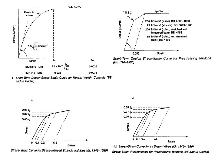
Strain compatibility method • The flexural strength of the prestressed concrete section is based on the compatibility of strain and equilibrium of forces action on the section at the stage of failure. • The flexural compressive stress in compressive zone closely follows the stress-strain curve of concrete. Stress-Strain distribution at failure
• Characteristics of Hognestad et. al’s stress blocks
Steps Involved in Strain Compatibility Method • Compute the effective strain εsc in steel due to prestress after allowing for an losses from the stress-strain curve for steel. • Assume a trail value for the neutral axis depth x and evaluate (εsu-εsc) from the strain diagram. • Using the stress strain curve for steel, determine the value of stress in steel at failure fpb corresponding to εsu. • Compute the total compression and tension • If the compressive Cu and tensile forces Tu are equal then the assumed value of x is correct. • Evaluate the ultimate moment Mu using the expression,
Selection of cross section for bending • The sections are broadly grouped under rectangular section, T-section, I-section and inverted T-section. Some variations of each type are shown under the corresponding broad groups.
Stress distribution in end block • A physical concept of the state of stress in the transverse direction , normal to the planes parallel with top and bottom surfaces of the beam may be obtained by considering these lines of forces as individual fibers acting as curved strut inserted between end force 2 P and the main body of the beam • The curvature of the struts being convex towards the centre line of the block, induces compressive stresses in zone A.
• In zone B the curvature is reversed in direction and struts tends to deflects outwards, separating from each other and consequently developing transverse tensile stresses. • In zone C the struts are straight and parallel so that no transverse stresses are induced only longitudinal stresses develop the zone.
• The idealised stress distribution in end block with the compressive and tensile stress path is shown below. • The bursting tension in the direction perpendicular to anchorage force
Design of anchorage zone reinforcement • The main reinforcement in the anchorage zone should be withstand the bursting tension, which is determined by the transverse stress distribution on the critical axis. • For plate and embedded type of anchorages the typical arrangement of reinforcement in end block is shown below
• Suitable pockets are generally provided behind the anchorages and the pockets are filled with mortar after prestressing operations. • There must always be enough space for the fixing and handling of the hydraulic jack especially in the soffit of beams.
• In case of end blocks, where bearing plates are positioned close to the edges of blocks shown below. The steel cage should be arranged so that the bearing plates do not overlap with it. • This precaution is necessary to prevent the concrete at the corners during stressing due to the different elastic modulus of the plane containing the reinforcement.
Limit state design criteria • Failure of one or more critical sections in flexure, shear, torsion or due to their combinations. • Bursting of prestressed concrete end blocks • Bearing failure at supports, anchorages or underconcentrated imposed loads. • Bond anchorage failure of reinforcement. • Failure of connections between precast and cast in situ elements. • Failure due to elastic instability of member.
Partial Pre-stressing • In partially prestressed members, limited tensile stresses are permitted in concrete under service loads with controls on the maximum width of cracks and depending upon the types of prestressing and environmental conditions. • The use of partial prestressing was first proposed by Emperger in 1939. • The main point in the favor of partial or limited prestressing is that untensioned reinforcement is required in the cross section of a prestressed temperature effects and handling stresses. • Hence this reinforcements such ass control of cracking and partially , for the ultimate limit state of collapse which can result in considerable reductions in the costlier high tensile steel. contributes to an overall saving in the cost of the structure.
Applications • Precast single or double-tee units and channel sections. • Prestressed concrete flat slab • Long-span bridge construction – Twin box girder – Cable stayed bridges • Prestressed concrete folded plate roof structure • Large capacity liquid retaining structures • Marine structures – Floating dockss – Off-shore oil drilling platforms – Gas and oil-storing vessels
Thank You