
High Resolution Xray Grating and Mirror Development at

- Slides: 30
High Resolution X-ray Grating and Mirror Development at MIT Mark Schattenburg Space Nanotechnology Laboratory Kavli Institute for Astrophysics and Space Research X-ray Science Analysis Group (XRSIG) AAS Annual Meeting Washington, DC January 5, 2014
High-resolution X-ray Diffraction Gratings and Mirrors • Critical-angle transmission (CAT) gratings • Thin-shell x-ray mirror fabrication: – Thermal air bearing slumping – Ion implant figure correction Schattenburg -- XR-SIG meeting, Jan. 5, 2014 2
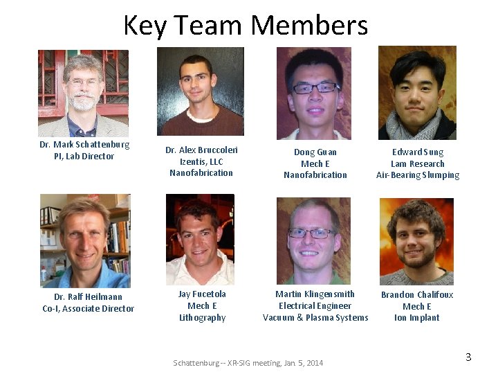
Key Team Members Dr. Mark Schattenburg PI, Lab Director Dr. Ralf Heilmann Co-I, Associate Director Dr. Alex Bruccoleri Izentis, LLC Nanofabrication Dong Guan Mech E Nanofabrication Edward Sung Lam Research Air-Bearing Slumping Jay Fucetola Mech E Lithography Martin Klingensmith Electrical Engineer Vacuum & Plasma Systems Brandon Chalifoux Mech E Ion Implant Schattenburg -- XR-SIG meeting, Jan. 5, 2014 3
CAT Prototype Grating Fabrication Progress Schattenburg -- XR-SIG meeting, Jan. 5, 2014 4
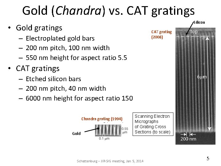
Gold (Chandra) vs. CAT gratings Silicon • Gold gratings CAT grating (2008) – Electroplated gold bars – 200 nm pitch, 100 nm width – 550 nm height for aspect ratio 5. 5 • CAT gratings – Etched silicon bars – 200 nm pitch, 40 nm width – 6000 nm height for aspect ratio 150 Chandra grating (1994) Gold Scanning Electron Micrographs of Grating Cross Sections (to scale) Schattenburg -- XR-SIG meeting, Jan. 5, 2014 5
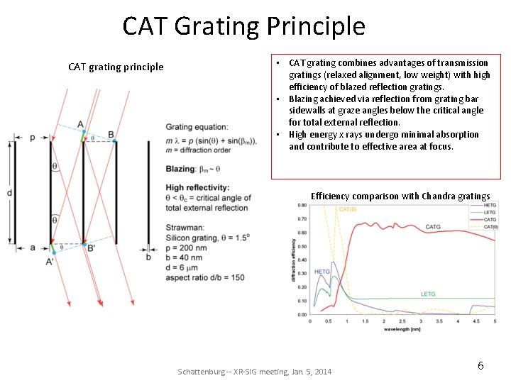
CAT Grating Principle CAT grating principle • CAT grating combines advantages of transmission gratings (relaxed alignment, low weight) with high efficiency of blazed reflection gratings. • Blazing achieved via reflection from grating bar sidewalls at graze angles below the critical angle for total external reflection. • High energy x rays undergo minimal absorption and contribute to effective area at focus. Efficiency comparison with Chandra gratings Schattenburg -- XR-SIG meeting, Jan. 5, 2014 6
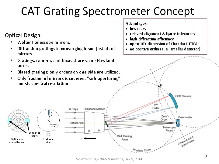
CAT Grating Spectrometer Concept Optical Design: • • • Wolter I telescope mirrors. Diffraction gratings in converging beam just aft of mirrors. Gratings, camera, and focus share same Rowland torus. Blazed gratings; only orders on one side are utilized. Only fraction of mirrors is covered: “sub-aperturing” boosts spectral resolution. CAT grating arrays Flight mirror assembly view Focal plane view Advantages: • low mass • relaxed alignment & figure tolerances • high diffraction efficiency • up to 10 X dispersion of Chandra HETGS • no positive orders (i. e. , smaller detector) z Schattenburg -- XR-SIG meeting, Jan. 5, 2014 7
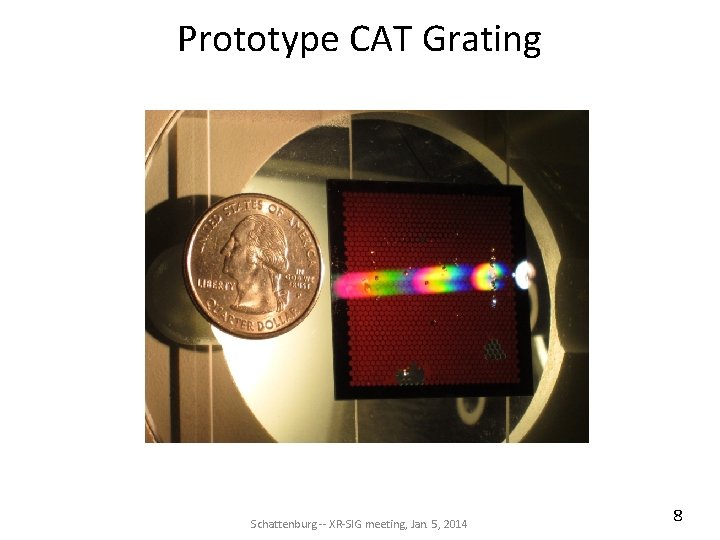
Prototype CAT Grating Schattenburg -- XR-SIG meeting, Jan. 5, 2014 8
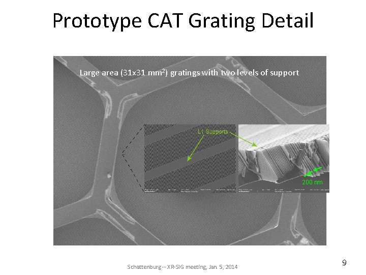
Prototype CAT Grating Detail Large area (31 x 31 mm 2) gratings with two levels of support 200 nm Schattenburg -- XR-SIG meeting, Jan. 5, 2014 9
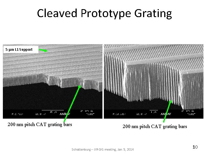
Cleaved Prototype Grating 5 µm L 1 Support 200 nm pitch CAT grating bars Schattenburg -- XR-SIG meeting, Jan. 5, 2014 10
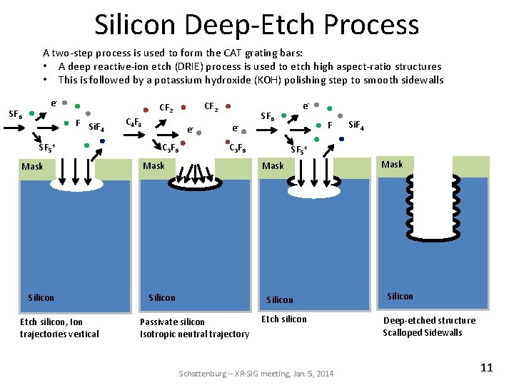
Silicon Deep-Etch Process A two-step process is used to form the CAT grating bars: • A deep reactive-ion etch (DRIE) process is used to etch high aspect-ratio structures • This is followed by a potassium hydroxide (KOH) polishing step to smooth sidewalls e- SF 6 CF 2 F Si. F 4 SF 5+ Mask Silicon Etch silicon, Ion trajectories vertical C 4 F 8 e. C 3 F 6 e- SF 6 C 3 F 6 Mask e. F SF 5+ Mask Silicon Passivate silicon Isotropic neutral trajectory Si. F 4 Etch silicon Schattenburg -- XR-SIG meeting, Jan. 5, 2014 Mask Silicon Deep-etched structure Scalloped Sidewalls 11
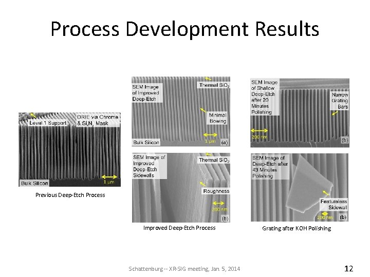
Process Development Results Previous Deep-Etch Process Improved Deep-Etch Process Schattenburg -- XR-SIG meeting, Jan. 5, 2014 Grating after KOH Polishing 12
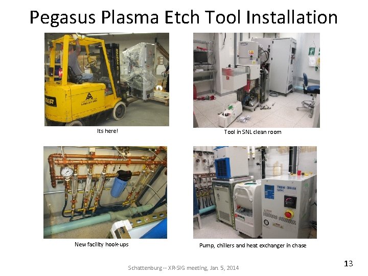
Pegasus Plasma Etch Tool Installation Its here! New facility hook-ups Tool in SNL clean room Pump, chillers and heat exchanger in chase Schattenburg -- XR-SIG meeting, Jan. 5, 2014 13
X-ray Mirrors Fabrication by Air Bearing Slumping Schattenburg -- XR-SIG meeting, Jan. 5, 2014 14
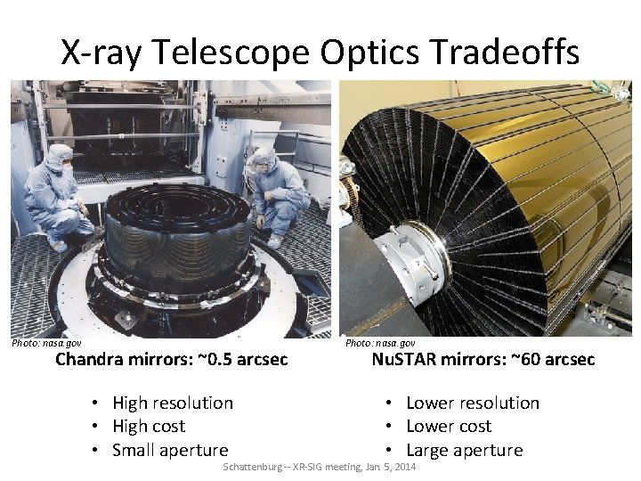
X-ray Telescope Optics Tradeoffs Photo: nasa. gov Chandra mirrors: ~0. 5 arcsec • High resolution • High cost • Small aperture Photo: nasa. gov Nu. STAR mirrors: ~60 arcsec • Lower resolution • Lower cost • Large aperture Schattenburg -- XR-SIG meeting, Jan. 5, 2014
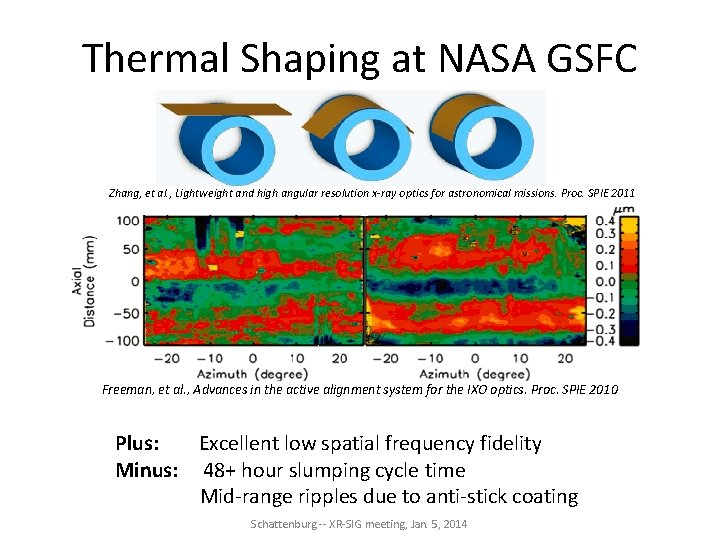
Thermal Shaping at NASA GSFC Zhang, et al. , Lightweight and high angular resolution x-ray optics for astronomical missions. Proc. SPIE 2011 Freeman, et al. , Advances in the active alignment system for the IXO optics. Proc. SPIE 2010 Plus: Excellent low spatial frequency fidelity Minus: 48+ hour slumping cycle time Mid-range ripples due to anti-stick coating Schattenburg -- XR-SIG meeting, Jan. 5, 2014
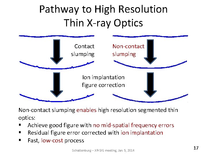
Pathway to High Resolution Thin X-ray Optics Contact slumping Non-contact slumping Ion implantation figure correction Non-contact slumping enables high resolution segmented thin optics: § Achieve good figure with no mid-spatial frequency errors § Residual figure error corrected with ion implantation § Fast, low-cost process Schattenburg -- XR-SIG meeting, Jan. 5, 2014 17
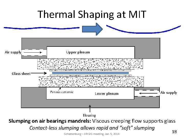
Thermal Shaping at MIT Air supply Upper plenum Glass sheet Lower plenum Air supply Slumping on air bearings mandrels: Viscous creeping flow supports glass Contact-less slumping allows rapid and “soft” slumping Schattenburg -- XR-SIG meeting, Jan. 5, 2014 18
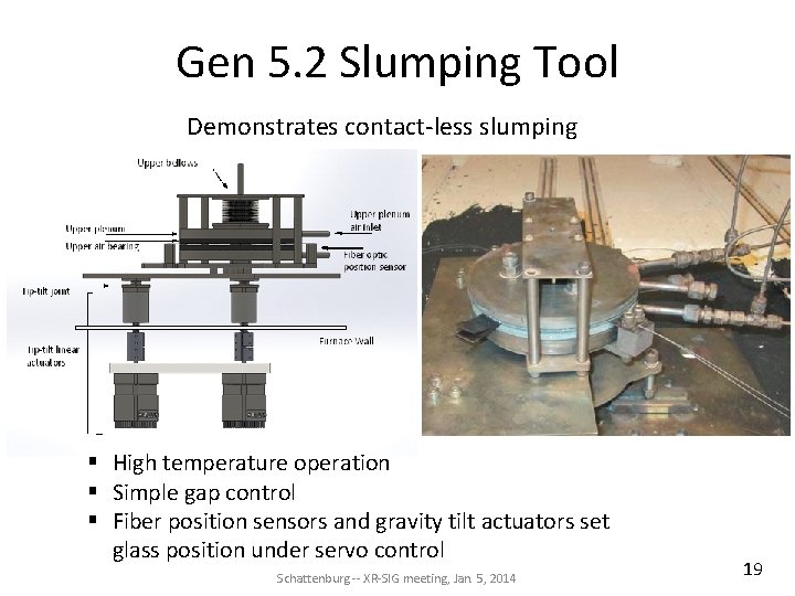
Gen 5. 2 Slumping Tool Demonstrates contact-less slumping § High temperature operation § Simple gap control § Fiber position sensors and gravity tilt actuators set glass position under servo control Schattenburg -- XR-SIG meeting, Jan. 5, 2014 19
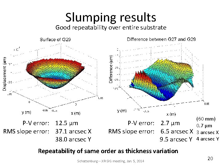
Slumping results Good repeatability over entire substrate P-V error: 12. 5 μm RMS slope error: 37. 1 arcsec X 38. 0 arcsec Y (60 mm) P-V error: 2. 7 μm 0. 7 μm RMS slope error: 6. 5 arcsec X 3 arcsec X 9. 5 arcsec Y 4 arcsec Y Repeatability of same order as thickness variation Schattenburg -- XR-SIG meeting, Jan. 5, 2014 20
X-ray Mirror Figure Correction via Ion Implantation Schattenburg -- XR-SIG meeting, Jan. 5, 2014 21
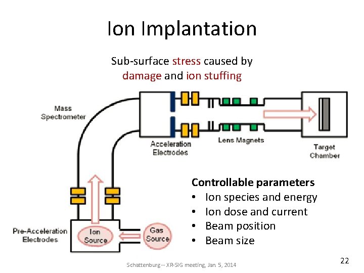
Ion Implantation Sub-surface stress caused by damage and ion stuffing Controllable parameters • Ion species and energy • Ion dose and current • Beam position • Beam size Schattenburg -- XR-SIG meeting, Jan. 5, 2014 22
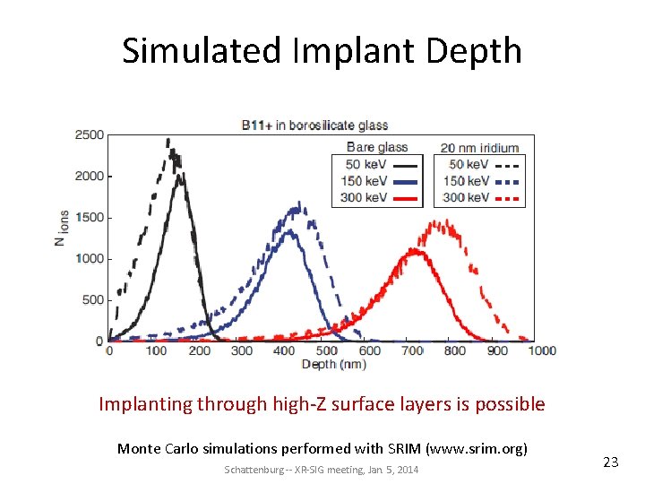
Simulated Implant Depth Implanting through high-Z surface layers is possible Monte Carlo simulations performed with SRIM (www. srim. org) Schattenburg -- XR-SIG meeting, Jan. 5, 2014 23
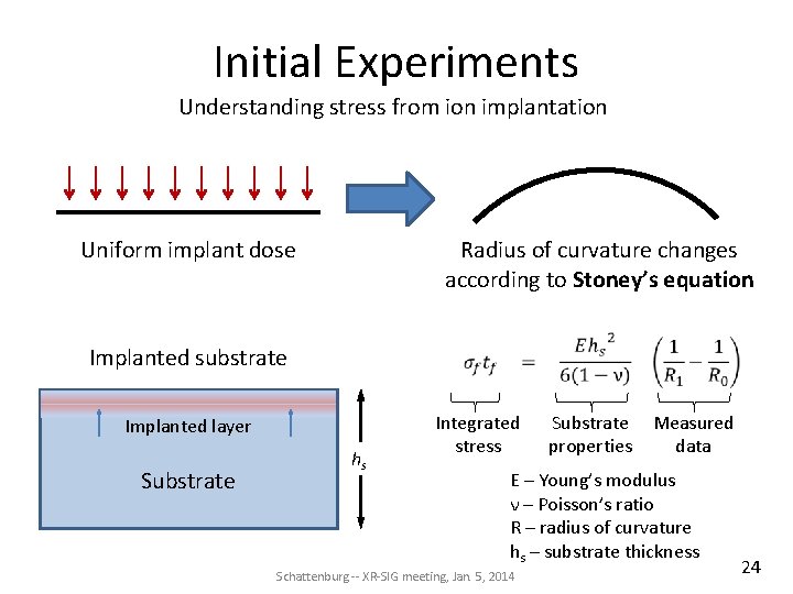
Initial Experiments Understanding stress from ion implantation Uniform implant dose Radius of curvature changes according to Stoney’s equation Implanted substrate Implanted layer Substrate hs Integrated stress Substrate Measured properties data E – Young’s modulus ν – Poisson’s ratio R – radius of curvature hs – substrate thickness Schattenburg -- XR-SIG meeting, Jan. 5, 2014 24
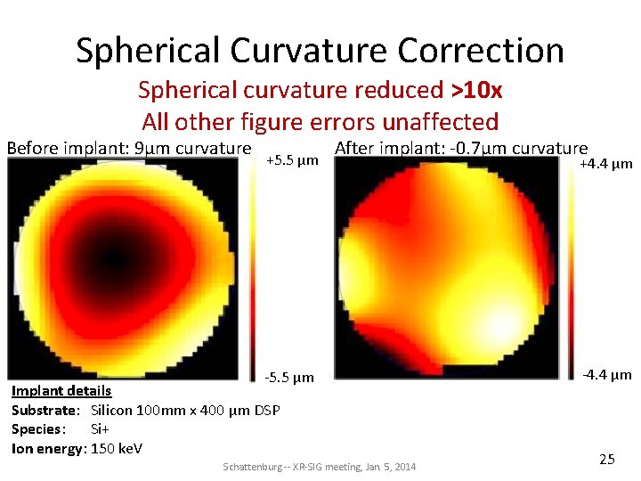
Spherical Curvature Correction Spherical curvature reduced >10 x All other figure errors unaffected Before implant: 9μm curvature +5. 5 μm After implant: -0. 7μm curvature -5. 5 μm Implant details Substrate: Silicon 100 mm x 400 μm DSP Species: Si+ Ion energy: 150 ke. V Schattenburg -- XR-SIG meeting, Jan. 5, 2014 +4. 4 μm -4. 4 μm 25
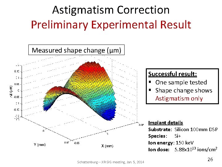
Astigmatism Correction Preliminary Experimental Result Measured shape change (μm) Successful result: § One sample tested § Shape change shows Astigmatism only Implant details Substrate: Silicon 100 mm DSP Species: Si+ Ion energy: 150 ke. V Ion dose: 5. 88 x 1013 ions/cm 2 Schattenburg -- XR-SIG meeting, Jan. 5, 2014 26
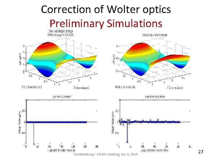
Correction of Wolter optics Preliminary Simulations Schattenburg -- XR-SIG meeting, Jan. 5, 2014 27
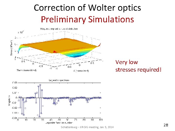
Correction of Wolter optics Preliminary Simulations Very low stresses required! Schattenburg -- XR-SIG meeting, Jan. 5, 2014 28
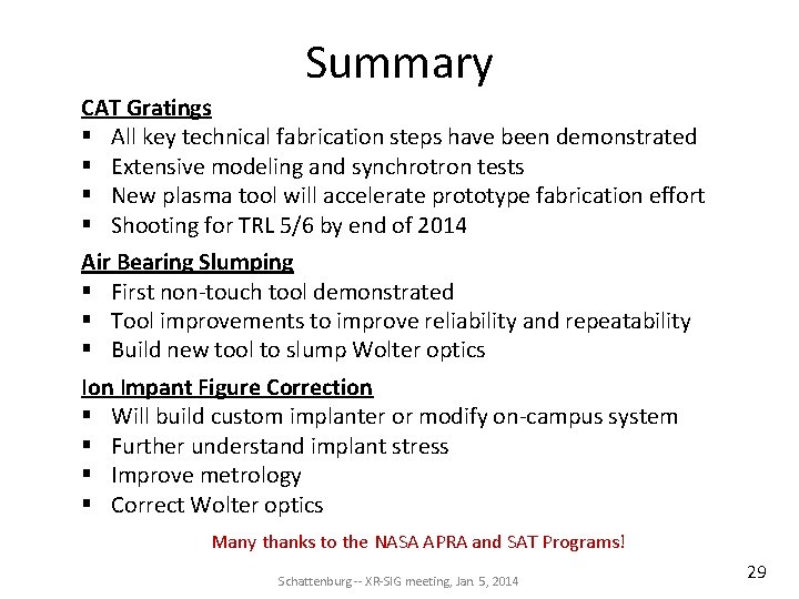
Summary CAT Gratings § All key technical fabrication steps have been demonstrated § Extensive modeling and synchrotron tests § New plasma tool will accelerate prototype fabrication effort § Shooting for TRL 5/6 by end of 2014 Air Bearing Slumping § First non-touch tool demonstrated § Tool improvements to improve reliability and repeatability § Build new tool to slump Wolter optics Ion Impant Figure Correction § Will build custom implanter or modify on-campus system § Further understand implant stress § Improve metrology § Correct Wolter optics Many thanks to the NASA APRA and SAT Programs! Schattenburg -- XR-SIG meeting, Jan. 5, 2014 29
Questions? Schattenburg -- XR-SIG meeting, Jan. 5, 2014 30